Technical Design Report for the: PANDA Detector Control System Strong Interaction Studies with Antiprotons - PANDA Collaboration
←
→
Transkription von Seiteninhalten
Wenn Ihr Browser die Seite nicht korrekt rendert, bitte, lesen Sie den Inhalt der Seite unten
Technical Design Report for the:
    PANDA Detector Control System

             (AntiProton Annihilations at Darmstadt)

Strong Interaction Studies with Antiprotons

                   PANDA Collaboration

                       October 13, 2020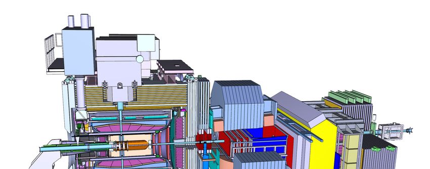
ii

                            The PANDA Collaboration

                                            2020-10-06 15:53:56
                       Università Politecnica delle Marche-Ancona, Ancona, Italy
      G. Barucca, F. Davì, G. Lancioni, P. Mengucci, L. Montalto, P. P. Natali, N. Paone, D. Rinaldi,
                                                L. Scalise
                                  Universität Basel, Basel, Switzerland
                              W. Erni, B. Krusche, M. Steinacher, N. Walford
              Institute of High Energy Physics, Chinese Academy of Sciences, Beijing, China
           N. Cao, Z. Liu, C. Liu, B. Liu, X. Shen, S. Sun, J. Tao, X. A. Xiong, G. Zhao, J. Zhao
              Ruhr-Universität Bochum, Institut für Experimentalphysik I, Bochum, Germany
     M. Albrecht, W. Alkakhi, S. Bökelmann, S. Coen, F. Feldbauer, M. Fink, J. Frech, V. Freudenreich,
      M. Fritsch, J. Grochowski, R. Hagdorn, F.H. Heinsius, T. Held, T. Holtmann, I. Keshk, H. Koch,
        B. Kopf, M. Kuhlmann, M. Kümmel, M. Küßner, J. Li, L. Linzen, J. Oppotsch, S. Pankonin,
        M. Pelizäus, A. Pitka, J. Reher, G. Reicherz, C. Schnier, M. Steinke, T. Triffterer, C. Wenzel,
                                                 U. Wiedner
                 Department of Physics, Bolu Abant Izzet Baysal University, Bolu, Turkey
                                      H. Denizli, N. Er, U. Keskin
                    Rheinische Friedrich-Wilhelms-Universität Bonn, Bonn, Germany
     R. Beck, C. Hammann, J. Hartmann, B. Ketzer, J. Müllers, M. Rossbach, B. Salisbury, C. Schmidt,
                                         U. Thoma, M. Urban
                                    Università di Brescia, Brescia, Italy
                                                A. Bianconi
Institutul National de C&D pentru Fizica si Inginerie Nucleara "Horia Hulubei", Bukarest-Magurele,
                                               Romania
                                   M. Bragadireanu, D. Pantea
               University of Technology, Institute of Applied Informatics, Cracow, Poland
           M. Domagala, G. Filo, E. Lisowski, F. Lisowski, M. Michałek, P. Poznański, J. Płażek
                         IFJ, Institute of Nuclear Physics PAN, Cracow, Poland
                  K. Korcyl, A. Kozela, P. Lebiedowicz, K. Pysz, W. Schäfer, A. Szczurek
                      AGH, University of Science and Technology, Cracow, Poland
                   M. Firlej, T. Fiutowski, M. Idzik, J. Moron, K. Swientek, P. Terlecki
                         Instytut Fizyki, Uniwersytet Jagiellonski, Cracow, Poland
       G. Korcyl, R. Lalik, A. Malige, P. Moskal, K. Nowakowski, W. Przygoda, N. Rathod, Z. Rudy,
                                           P. Salabura, J. Smyrski
             FAIR, Facility for Antiproton and Ion Research in Europe, Darmstadt, Germany
                      I. Augustin, R. Böhm, I. Lehmann, L. Schmitt, V. Varentsov
            GSI Helmholtzzentrum für Schwerionenforschung GmbH, Darmstadt, Germany
  M. Al-Turany, A. Belias, H. Deppe, R. Dzhygadlo, H. Flemming, A. Gerhardt, K. Götzen, A. Heinz,
 P. Jiang, R. Karabowicz, S. Koch, U. Kurilla, D. Lehmann, J. Lühning, U. Lynen, H. Orth, K. Peters,
  J. Rieger, T. Saito, G. Schepers, C. J. Schmidt, C. Schwarz, J. Schwiening, A. Täschner, M. Traxler,
                                          B. Voss, P. Wieczorek
                          Joint Institute for Nuclear Research, Dubna, Russia
        V. Abazov, G. Alexeev, V. A. Arefiev, V. Astakhov, M. Yu. Barabanov, B. V. Batyunya, V.
       Kh. Dodokhov, A. Efremov, A. Fechtchenko, A. Galoyan, G. Golovanov, E. K. Koshurnikov, Y.
       Yu. Lobanov, A. G. Olshevskiy, A. A. Piskun, A. Samartsev, S. Shimanski, N. B. Skachkov, A.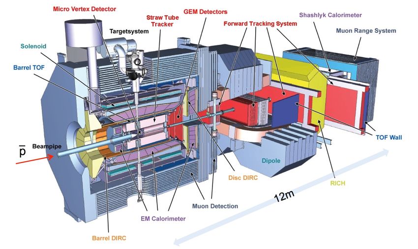
iii

    N. Skachkova, E. A. Strokovsky, V. Tokmenin, V. Uzhinsky, A. Verkheev, A. Vodopianov, N.
                                          I. Zhuravlev
                       University of Edinburgh, Edinburgh, United Kingdom
                                       D. Branford, D. Watts
              Friedrich-Alexander-Universität Erlangen-Nürnberg, Erlangen, Germany
                   M. Böhm, W. Eyrich, A. Lehmann, D. Miehling, M. Pfaffinger
                            Northwestern University, Evanston, U.S.A.
                              N. Quin, L. Robison, K. Seth, T. Xiao
                 Università di Ferrara and INFN Sezione di Ferrara, Ferrara, Italy
                                            D. Bettoni
                 Goethe-Universität, Institut für Kernphysik, Frankfurt, Germany
                A. Ali, A. Hamdi, M. Himmelreich, M. Krebs, S. Nakhoul, F. Nerling
                   Frankfurt Institute for Advanced Studies, Frankfurt, Germany
                       A. Belousov, I. Kisel, G. Kozlov, M. Pugach, M. Zyzak
                       INFN Laboratori Nazionali di Frascati, Frascati, Italy
                              N. Bianchi, P. Gianotti, V. Lucherini
              Dept of Physics, University of Genova and INFN-Genova, Genova, Italy
                                             G. Bracco
           Justus-Liebig-Universität Gießen II. Physikalisches Institut, Gießen, Germany
Y. Bettner, S. Bodenschatz, K.T. Brinkmann, L. Brück, S. Diehl, V. Dormenev, M. Düren, T. Erlen,
 K. Föhl, C. Hahn, A. Hayrapetyan, J. Hofmann, S. Kegel, M. Kesselkaul, I. Köseoglu, A. Kripko,
W. Kühn, J. S. Lange, V. Metag, M. Moritz, M. Nanova, R. Novotny, P. Orsich, J. Pereira-de-Lira,
  M. Peter, M. Sachs, M. Schmidt, R. Schubert, H. Stenzel, M. Straube, M. Strickert, U. Thöring,
                              T. Wasem, B. Wohlfahrt, H.G. Zaunick
                IRFU, CEA, Université Paris-Saclay, Gif-sur-Yvette Cedex, France
                                     E. Tomasi-Gustafsson
                         University of Glasgow, Glasgow, United Kingdom
                                  D. Glazier, D. Ireland, B. Seitz
        Birla Institute of Technology and Science, Pilani, K K Birla Goa Campus, Goa, India
                                      P.N. Deepak, A. Kulkarni
  KVI-Center for Advanced Radiation Technology (CART), University of Groningen, Groningen,
                                         Netherlands
   R. Kappert, M. Kavatsyuk, H. Loehner, J. Messchendorp, V. Rodin, P. Schakel, S. Vejdani
                     Gauhati University, Physics Department, Guwahati, India
                                        K. Dutta, K. Kalita
                    University of Science and Technology of China, Hefei, China
                        G. Huang, D. Liu, H. Peng, H. Qi, Y. Sun, X. Zhou
                           Universität Heidelberg, Heidelberg, Germany
                                             M. Kunze
                    Department of Physics, Dogus University, Istanbul, Turkey
                                            K. Azizi
                 Forschungszentrum Jülich, Institut für Kernphysik, Jülich, Germany
     A. Derichs, R. Dosdall, W. Esmail, A. Gillitzer, F. Goldenbaum, D. Grunwald, L. Jokhovets,
J. Kannika, P. Kulessa, S. Orfanitski, G. Pérez Andrade, D. Prasuhn, E. Prencipe, J. Pütz, J. Ritman,
     E. Rosenthal, S. Schadmand, R. Schmitz, A. Scholl, T. Sefzick, V. Serdyuk, T. Stockmanns,
                       D. Veretennikov, P. Wintz, P. Wüstner, H. Xu, Y. Zhou
             Chinese Academy of Science, Institute of Modern Physics, Lanzhou, China
                          X. Cao, Q. Hu, Z. Li, H. Li, Y. Liang, X. Ma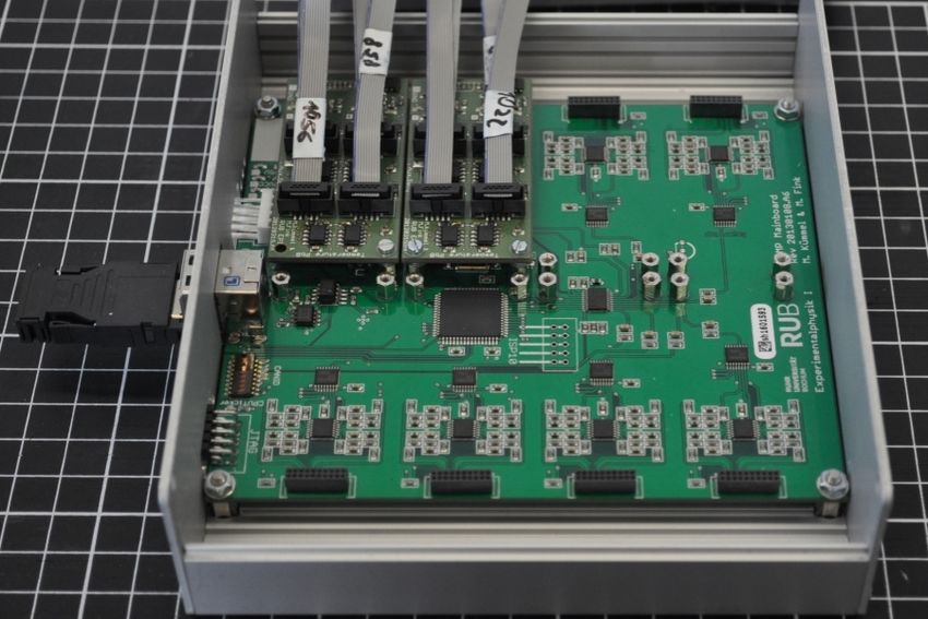
iv

                          INFN Laboratori Nazionali di Legnaro, Legnaro, Italy
                                              V. Rigato
                         Lunds Universitet, Department of Physics, Lund, Sweden
                                               L. Isaksson
            Johannes Gutenberg-Universität, Institut für Kernphysik, Mainz, Germany
 P. Achenbach, O. Corell, A. Denig, M. Distler, M. Hoek, W. Lauth, H. H. Leithoff, Z. Liu, H. Merkel,
             U. Müller, J. Pochodzalla, S. Schlimme, C. Sfienti, M. Thiel, M. Zambrana
                            Helmholtz-Institut Mainz, Mainz, Germany
 S. Ahmed , S. Bleser, M. Bölting, L. Capozza, A. Dbeyssi, A. Ehret, R. Klasen, R. Kliemt, F. Maas,
 S. Maldaner, C. Motzko, O. Noll, S. Pflüger, D. Rodríguez Piñeiro, F. Schupp, M. Steinen, S. Wolff,
                                          I. Zimmermann
            Research Institute for Nuclear Problems, Belarus State University, Minsk, Belarus
                            A. Fedorov, D. Kazlou, M. Korzhik, O. Missevitch
                          Moscow Power Engineering Institute, Moscow, Russia
                               A. Balashoff, A. Boukharov, O. Malyshev
     Institute for Theoretical and Experimental Physics named by A.I. Alikhanov of National Research
                               Centre "Kurchatov Institute”, Moscow, Russia
     P. Balanutsa, V. Chernetsky, A. Demekhin, A. Dolgolenko, P. Fedorets, A. Gerasimov, A. Golubev,
     V. Goryachev, A. Kantsyrev, D. Y. Kirin, N. Kristi, E. Ladygina, E. Luschevskaya, V. A. Matveev,
                                      V. Panjushkin, A. V. Stavinskiy
                Nuclear Physics Division, Bhabha Atomic Research Centre, Mumbai, India
                        K. N. Basant, H. Kumawat, B. Roy, A. Saxena, S. Yogesh
                 Westfälische Wilhelms-Universität Münster, Münster, Germany
D. Bonaventura, P. Brand, C. Fritzsch, S. Grieser, C. Hargens, A.K. Hergemöller, B. Hetz, N. Hüsken,
                              J. Kellers, A. Khoukaz, C. Mannweiler
                 Suranaree University of Technology, Nakhon Ratchasima, Thailand
      D. Bumrungkoh, C. Herold, K. Khosonthongkee, C. Kobdaj, A. Limphirat, K. Manasatitpong,
      T. Nasawad, S. Pongampai, T. Simantathammakul, P. Srisawad, N. Wongprachanukul, Y. Yan
                                    Nankai University, Nankai, China
                                       C. Yu, X. Zhang, W. Zhu
                            Novosibirsk State University, Novosibirsk, Russia
                              A. E. Blinov, S. Kononov, E. A. Kravchenko
                     Budker Institute of Nuclear Physics, Novosibirsk, Russia
E. Antokhin, A. Yu. Barnyakov, K. Beloborodov, V. E. Blinov, I. A. Kuyanov, S. Pivovarov, E. Pyata,
                                           Y. Tikhonov
Institut de Physique Nucléaire, CNRS-IN2P3, Univ. Paris-Sud, Université Paris-Saclay, 91406, Orsay
                                         cedex, France
                                     R. Kunne, B. Ramstein
                            University of Wisconsin Oshkosh, Oshkosh, U.S.A.
                                      G. Hunter, M. Lattery, H. Pace
             Dipartimento di Fisica, Università di Pavia, INFN Sezione di Pavia, Pavia, Italy
                                                 G. Boca
                                University of West Bohemia, Pilsen, Czech
                                                D. Duda
            Charles University, Faculty of Mathematics and Physics, Prague, Czech Republic
      M. Finger, M. Finger, Jr., A. Kveton, M. Pesek, M. Peskova, I. Prochazka, M. Slunecka, M. Volf
   Czech Technical University, Faculty of Nuclear Sciences and Physical Engineering, Prague, Czech
                                               Republic
P. Gallus, V. Jary, O. Korchak, M. Marcisovsky, G. Neue, J. Novy, L. Tomasek, M. Tomasek, M. Virius,
v

                                              V. Vrba
A.A. Logunov Institute for High Energy Physics of the National Research Centre “Kurchatov Institute”,
                                          Protvino, Russia
V. Abramov, S. Bukreeva, S. Chernichenko, A. Derevschikov, V. Ferapontov, Y. Goncharenko, A. Levin,
 E. Maslova, Y. Melnik, A. Meschanin, N. Minaev, V. Mochalov, V. Moiseev, D. Morozov, L. Nogach,
 S. Poslavskiy, A. Ryazantsev, S. Ryzhikov, P. Semenov, I. Shein, A. Uzunian, A. Vasiliev, A. Yakutin
                     Sikaha-Bhavana, Visva-Bharati, WB, Santiniketan, India
                                            U. Roy
                      University of Sidney, School of Physics, Sidney, Australia
                                              B. Yabsley
   National Research Centre "Kurchatov Institute" B. P. Konstantinov Petersburg Nuclear Physics
                            Institute, Gatchina, St. Petersburg, Russia
    S. Belostotski, G. Fedotov, G. Gavrilov, A. Izotov, S. Manaenkov, O. Miklukho, A. Zhdanov
                         Kungliga Tekniska Högskolan, Stockholm, Sweden
                                  A. Atac, T. Bäck, B. Cederwall
                            Stockholms Universitet, Stockholm, Sweden
                         K. Makonyi, M. Preston, P.E. Tegner, D. Wölbing
   Sardar Vallabhbhai National Institute of Technology, Applied Physics Department, Surat, India
                                       K. Gandhi, A. K. Rai
            Veer Narmad South Gujarat University, Department of Physics, Surat, India
                                          S. Godre
                            Florida State University, Tallahassee, U.S.A.
                             V. Crede, S. Dobbs, P. Eugenio, D. Lersch
                               INFN Sezione di Torino, Torino, Italy
               D. Calvo, P. De Remigis, A. Filippi, G. Mazza, A. Rivetti, R. Wheadon
                   Università di Torino and INFN Sezione di Torino, Torino, Italy
                                       M. P. Bussa, S. Spataro
                   Politecnico di Torino and INFN Sezione di Torino, Torino, Italy
                                         F. Iazzi, A. Lavagno
                  Università di Trieste and INFN Sezione di Trieste, Trieste, Italy
                                             A. Martin
           Uppsala Universitet, Institutionen för fysik och astronomi, Uppsala, Sweden
A. Akram, H. Calen, W. Ikegami Andersson, T. Johansson, A. Kupsc, P. Marciniewski, M. Papenbrock,
                               J. Regina, K. Schönning, M. Wolke
           Instituto de Física Corpuscular, Universidad de Valencia-CSIC, Valencia, Spain
                                               J. Diaz
              Sardar Patel University, Physics Department, Vallabh Vidynagar, India
                                        V. Pothodi Chackara
                      National Centre for Nuclear Research, Warsaw, Poland
   A. Chlopik, G. Kesik, D. Melnychuk, J. Tarasiuk, M. Wojciechowski, S. Wronka, B. Zwieglinski
 Österreichische Akademie der Wissenschaften, Stefan Meyer Institut für Subatomare Physik, Wien,
                                             Austria
     C. Amsler, P. Bühler, N. Kratochwil, J. Marton, W. Nalti, D. Steinschaden, E. Widmann,
                                   S. Zimmermann, J. Zmeskal
vi

Editors:               Tobias Triffterer           Email: tobias@ep1.ruhr-uni-bochum.de
                       Florian Feldbauer           Email: florian@ep1.ruhr-uni-bochum.de
                       Alexandru Mario Bragadireanu Email: mario.bragadireanu@nipne.ro
Technical Coordinator: Lars Schmitt                Email: l.schmitt@gsi.de
Deputy:                Anastasios Belias           Email: a.belias@gsi.de
Spokesperson:          Klaus Peters                Email: k.peters@gsi.de
Deputy:                Tord Johansson              Email: tord.johansson@physics.uu.se
vii

                            Abstract

The PANDA Detector Control System (abbreviated DCS) has the
purpose to monitor and control all the experimental equipment of
the PANDA detector. It shall ensure the safe and efficient operation
of the PANDA experiment and contribute to the collection of high-
quality data.
Building a DCS requires the cooperation of both DCS experts
and experts from the individual PANDA subsystems. Therefore,
this TDR explains the underlying concepts of the PANDA DCS,
illustrates the main software choices and provides several examples
from PANDA subsystem for the DCS on the subsystem level.
Information on the design of the DCS of a particular subsystem
can be found in the corresponding TDR and other publications of
this subsystem.

Chapter 1 gives a brief description of the PANDA experiment and
its physics program.
Chapter 2 describes the main requirements for a proper DCS and
the architectural concepts of the PANDA DCS.
Chapter 3 forms the main part of this TDR. It explains in detail
the components of the PANDA DCS, the software chosen to fulfill
the task and the communication paths between the components.
In chapter 4, hardware and software projects are presented that
can be commonly used by several PANDA subsystems. In addition,
some examples for the implementation of the DCS for an individual
device or subsystem are introduced.
Chapter 5 discusses project management issues like the expected
costs for the hardware not covered by the PANDA subsystems.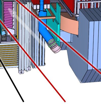
viii

The use of registered names, trademarks, etc. in this publication does not imply, even in
the absence of specific statement, that such names are exempt from the relevant laws and
regulations and therefore free for general use.
Contents
Abstract vii 3.5 Finite State Machine . . . . . . . . . 24
3.5.1 Purpose and Concept . . . . . . . 24
Executive Summary 1
3.5.2 List of States . . . . . . . . . . . . 24
1 The PANDA Experiment 3 3.5.3 Transitions between States . . . . 25
1.1 The PANDA Scientific Program . . . 3 3.6 Persistent Storage . . . . . . . . . . . 26
1.2 The FAIR high energy store ring . . . 3 3.6.1 Introduction . . . . . . . . . . . . 26
1.3 The PANDA Experimental Setup . . 4 3.6.2 Database Concepts . . . . . . . . 26
1.3.1 PANDA Targets . . . . . . . . . . 4 3.6.3 EPICS Archivers . . . . . . . . . 27
1.3.2 PANDA Spectrometer . . . . . . . 4 3.6.4 Software Selection . . . . . . . . . 28
1.4 PANDA Data aquisition . . . . . . . . 6 3.6.5 High Availability . . . . . . . . . . 28
1.5 PANDA Infrastructure . . . . . . . . 7 3.7 Communication with External Systems 29
3.8 Interfaces between DCS, ECS and DAQ 29
2 Detector Control System Architecture 9 3.9 Interfaces between DCS and FEE . . 29
2.1 Requirements and Design Goals . . . 9 3.9.1 Front-End Electronics . . . . . . . 29
2.2 PANDA Online Systems Overview . . 9 3.9.2 Basic Concept . . . . . . . . . . . 29
2.3 Hardware Architecture . . . . . . . . 10 3.9.3 Configuration Namespaces . . . . 30
2.4 Software Components . . . . . . . . . 11 3.9.4 Operation Modes . . . . . . . . . 30
3.9.5 Configuration Database . . . . . . 31
3 Control System implementation 15
3.9.6 Initiating Configuration Loading . 32
3.1 Core Software Choice: EPICS . . . . 15
3.9.7 Monitoring the Front-End Elec-
3.2 Technical Details of EPICS-based DCS 15 tronics . . . . . . . . . . . . . . . 33
3.2.1 Introduction . . . . . . . . . . . . 15
3.2.2 Device Support . . . . . . . . . . 16 4 Common Solutions for Sub-System
3.2.3 EPICS IOCs . . . . . . . . . . . . 16 Controls 37
3.2.4 Network Structure . . . . . . . . . 17 4.1 Hardware . . . . . . . . . . . . . . . . 37
3.2.5 PV Naming Convention . . . . . . 17 4.1.1 Field Devices . . . . . . . . . . . . 37
3.2.6 Channel Access Gateway . . . . . 18 4.1.2 EMC LED Pulser . . . . . . . . . 37
3.2.7 Failover Considerations . . . . . . 19 4.1.3 Temperature Monitoring for the
EMC . . . . . . . . . . . . . . . . 38
3.2.8 Machine Safety . . . . . . . . . . 19
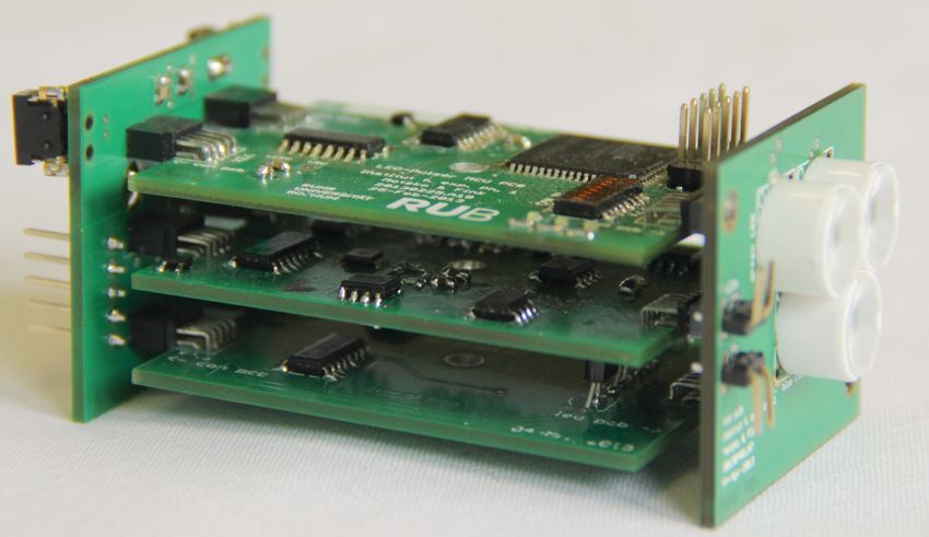
4.1.4 Fault Tolerant Local Monitoring
3.2.9 EPICS Open License . . . . . . . 20 Control Board . . . . . . . . . . . 39
3.3 Graphical User Interface . . . . . . . 20 4.2 Device Drivers . . . . . . . . . . . . . 39
3.3.1 Control System Studio . . . . . . 20 4.2.1 Device Drivers for Single Board
3.3.2 Operator Interface . . . . . . . . . 20 Computers . . . . . . . . . . . . . 39
3.4 Alarm Handling . . . . . . . . . . . . 21 4.2.2 isegHAL . . . . . . . . . . . . . . 39
3.4.1 EPICS Alarm Thresholds . . . . . 21 4.3 FEMC Prototype “Proto192” . . . . . 40
3.4.2 Alarm Server . . . . . . . . . . . . 22 4.3.1 Introduction . . . . . . . . . . . . 40
3.4.3 Alarming Operators . . . . . . . . 23 4.3.2 Beamtimes . . . . . . . . . . . . . 41
3.4.4 Informing Experts . . . . . . . . . 23 4.3.3 DCS Setup . . . . . . . . . . . . . 41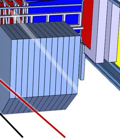
x

     4.3.4      Used Software . . . . . . . . . . .     43
     4.3.5      Testbeam Results . . . . . . . . .      44
    4.4      Test-Bed at HIM . . . . . . . . . . .      44

5 Project Management                                    47
    5.1      Project Management . . . . . . . . .       47
    5.2      Timeline . . . . . . . . . . . . . . . .   47
    5.3      Cost Estimation . . . . . . . . . . . .    47

List of Acronyms                                        49

List of Figures                                         51

List of Tables                                          53
Executive Summary
This report presents the requirements and design of titions. Each sub-detector has its own control and
the detector control system (DCS) for the PANDA field layers which are separated by a network gate-
experiment. way from each other. These partitions are brought
The PANDA detector at FAIR, Darmstadt, is de- togehter by the supervisory layer.
5 signed for measurements of reactions induced by An alarm system notifies the shift crew if a param- 5
high intensity antiproton beams with a momentum eter is outside a predefined range. This alarm noti-
in the range of 1.5 GeV/c up to 15 GeV/c interacting fication has two stages: A warning for small devia-
with hydrogen or nuclear targets. The main top- tions which do not cause an immediate harm to the
ics of the experiment are hadron spectroscopy, in detector, and an alarm for severe problems which
10 particular the search of exotic states in the charmo- require immediate actions from the shift crew. 10
nium mass region and spectroscopy of multi-strange For quality management of the recorded physics
baryons, investigation of properties of mesons em- data, all parameters controlled and monitored by
bedded in nuclear matter, spectroscopy of double the DCS are archived and stored in a common
hypernuclei and study of the nucleon structure. database which can be accessed at any time. The
15 The application of a fixed target at PANDA results archived data includes the value of the parameters 15
in a forward peaking of the reaction products. To and alarm states.
ensure a geometrical acceptance close to 4π and a The PANDA DCS will be based on Experimental
good momentum resolution in a wide range, the Physics and Industrial Control System (EPICS)
chosen setup consists of two spectrometers: the which offers a distributed control system architec-
20 target spectrometer (TS) based on a 2 T supercon- ture. 20
ducting solenoid magnet surrounding the interac-
tion point and the forward spectrometer (FS) us- This document is organized in the following way:
ing a large gap 2 Tm dipole magnet for momentum In the following chapter an outline of the PANDA
analysis of particles emitted at the most forward physics program, the accelerator center and the lay-
25 angles. The FS covers an angular range of ±10◦ in out of the PANDA detector are presented.
the horizontal plane and ±5◦ in the vertical plane. In chapter 2 the basic requirements for the PANDA 25
The PANDA DCS ensures the safe operation of the DCS are formulated and the general concepts of the
detector by monitoring and controlling the neces- control system are proposed.
sary detector operation parameters like tempera- Technical details of the used software components
30 tures, voltages, gas flow etc. The DCS has to fulfill and setup of the DCS as well as a general definition
several basic requirements: It should be scalable to of the interfaces to other PANDA systems like the 30
allow an easy upgrade for the individual phases of DAQ and the HESR are described in chapter 3.
the PANDA experiment, it should be distributed to
Chapter 4 presents an overview of custom develop-
avoid a single point of failure and it should have an
ments for the control system of different PANDA
intuitive user frontend. The operator in the con-
sub-systems which can be used as common solu-
35
trol room should be notified about any problems
tions. In addition tests performed with prototypes 35
occuring during the operation.
of PANDA sub-systems are presented.
The design of the DCS is structured into three
The last chapter is devoted to organizational is-
layers: a common supervisory layer for the whole
sues such as responsibilities and timelines for the
PANDA detector which consists of the graphical
PANDA DCS.
40
user interfaces in the control room, a central storage
and the interfaces to “external” systems such as the
accelerator or the magnets. This layer is followed
by the control layer where the actual monitoring
45 and controlling takes place. The last layer is the
field layer which consits of all the devices needed to
operate the detector.
For maintenance and tests of the individual PANDA
sub-systems the last two layers are designed as par-2
1       The PANDA Experiment

     1.1     The PANDA Scientific                          production rate of 2 · 107 s−1 governs the experi-
                                                           ment interaction rate in the order of cycle-averaged
             Program                                       1 · 107 s−1 . The stored antiprotons do not have a
                                                           bunch structure, and with 10% to 20% allocated to
     The AntiProton ANnihilations at DArmstadt             a barrier bucket, the antiprotons are continuously                                               5

     (PANDA) experiment [1], at the future Facility for    spread over about 80% of the HESR circumference.
5    Antiproton and Ion Research (FAIR), envisages a
     physics core program [2] that comprises
                                                                                                    RF                            stochastic cooling
                                                                                              barrier bucket                           kickers

       • charmonium spectroscopy with precision mea-
                                                                              SPARC                               KOALA                            SPARC

                                                                                                               HESR

                                                                                                                                      signal cooling
         surements of mass, width, and decay branches;
                                                                       Dipole magnet

                                                                                                                                             paths
                                                                       Quadrupole magnet
                                                                       Sextupole or steerer magnet

                                                                                                                                           tic
                                                                                                                                   stochas
                                                                       Solenoid magnet
                                                                                                           0              50m
                                                                       Injection equipment

       • the investigation of states that are assumed to                RF cavity, stochastic cooling devices

10       have more exotic configurations like multiquark                                              injection
                                                                                                        kicker
                                                                                                      magnets
                                                                                                                  PANDA

         states, charmed hybrids, and glueballs;                  p,pbar,HI
                                                                  (from CR)
                                                                                                                          stochastic cooling
                                                                                                                               pickups

       • the search for medium modifications of Figure 1.1: Schematic overview of the HESR. The
         charmed hadrons in nuclear matter;     PANDA detector is located at the bottom. Possible lo-
       • the γ-ray spectroscopy of hypernuclei, in par- cations of the other experiments are indicated at the
                                                        top. Standard operation has the antiproton injection
15       ticular double Λ states.
                                                           from CR from the bottom left, or protons at reversed
                                                           field polarities.
     In the charmonium and open-charm regions, many
     new states have been observed in the last years,
     that do not match the patterns predicted in those
     regimes [3]. There are even several states unam-    Two complementary operating modes are planned,
20   biguously being of exotic nature, raising the ques- named high luminosity mode and high resolution
     tion about the underlying mechanism to form such    mode. The high luminosity mode with ∆p/p =                                                        10

     kind of states [4].                                 10−4 , stochastic cooling and a pellet target density
                                                         of 4 · 1015 cm−2 will have an average luminosity of
     The production of charmonium and open-charm
                                                         up to L = 1.6 · 1032 cm−2s−1 . For the high reso-
     states in e+ e− interactions are restricted to ini-
                                                         lution mode ∆p/p = 5 · 10−5 will be achieved with
     tial spin-parities of J P C = 1−− . This limits the
                                                         stochastic cooling and will operate in conjunction
25
                                                                                                                                                           15
     possibility to precisely scan and investigate these
                                                         with a cluster jet target to limit the energy broad-
     resonances in formation reactions. The use of p̄p
                                                         ening caused by the target. The cycle-averaged lu-
     annihilation does not suffer from this limitation.
                                                         minosity is expected to be L = 1.6 · 1031 cm−2 s−1 .
     Combined with the excellent energy resolution of
                                                         The values described here are the design values for
     down to about 25 keV, this kind of reactions offer
                                                         the HESR and the PANDA experiment.
30
                                                                                                                                                           20
     unique opportunity to perform hadron and charmo-
     nium spectroscopy in the accessible energy range.   In the modularized start version the recuperated
                                                         experimental storage ring (RESR) will not be avail-
                                                         able to accumulate the antiprotons. Instead, the ac-
     1.2 The FAIR high energy                            cumulation process has to be done with the HESR
                                                         itself. The absence of the dedicated RESR has the                                                 25
               store ring                                implication that, on one hand, the maximum num-
                                                         ber of antiprotons is reduced by one order of magni-
35   The combination of the high energy store ring tude to Nmax = 1010 compared to the high luminos-
     (HESR) and PANDA aims at both high reaction ity mode. On the other hand the accumulation pro-
     rates and high resolution to be able to study rare cess, which takes a finite time, cannot be performed                                               30

     production processes and small branching ratios. in parallel but further worsens the duty cycle (for
     With a design value of 1011 stored antiprotons more detail see [5]). However, since the full version
40   for beam momenta from 1.5 GeV/c to 15 GeV/c of FAIR is decided to be built, the requirements for
     and high density targets the anticipated antiproton detectors of the PANDA experiment have to be set
4
up regarding the original design values. radius measures from 2.5 cm to 15 cm. A complete
description is found in the corresponding TDR [7].
1.3 The PANDA Experimental
Straw Tube Tracker An assembly of aluminized
Setup boPET tubes with diameters of 10 mm is operated
at over pressure to make them self supporting. In 5
The cut-out of the PANDA setup in figure 1.2 shows those a single anode wire is spanned. In total 4636
5 the detector components. The state of the art de- straw tube tracker (STT) tubes are arranged in 27
sign covers nearly 4π of the solid angle for neutral as layers around the MVD. With a length of 150 cm
well as charged particles in a very broad momentum and an outer radius of 41.8 cm a coordinate resolu-
range. It can be divided into the target spectrom- tion of 150 µm in the transversal plane and about 10
eter (TS) and the forward spectrometer (FS) part 3 mm in the longitudinal direction is achieved. For
10 which is defined by the spectrometer magnet ar- more details the reader is referred to the technical
rangement. The lifetime of the PANDA detector is design report (TDR) [8].
divided into different phases. Some detector compo-
nents will not be available when PANDA starts data
tacking for the first time, but will be integrated as Forward GEM Detectors gas electron multiplier
15 an upgrade at later phases of the experiment. The (GEM) detectors have proven in several applica- 15
start version of the detector, which also includes the tions excellent high rate capabilities combined with
detector control system, is called the “Day-1” setup. a large area coverage at a small form factor. Three
stations are placed between 1.1 m and 1.9 m down-
stream of the interaction point and are detecting
charged particle tracks at polar angles below 22◦ 20
1.3.1 PANDA Targets to extend the acceptance of the STT into forward
directions.
20 The PANDA Target Spectrometer is designed to al-
low the installation of different targets. For hydro-
gen as target material both Cluster Jet Targets and Barrel DIRC The barrel detector of internally re-
Pellet Targets are being prepared. One main tech- flected cherenkov light (DIRC) covers particle iden-
nical challenge is the distance of 2 m between the tification in the polar angle range of 22 < θ < 140
◦ ◦
25
25 target injection point and the dumping region. and is based on the successful BaBar DIRC de-
tector [9]. 1.7 cm thick fused silica slabs are sur-
The cluster jet target has a constant thickness as a
rounding the beam pipe in a radial distance of
function of time whereas a pellet target with aver-
45 cm to 54 cm. As a segmented photon read-
age velocities of around 50 m/s and average pellet
out Micro-Channel Plate (MCP) Photo Multiplier 30
spacing of 3 mm has pellet target density variations
Tubes (PMTs) were chosen which are by design in-
30 on the 10-100 µs timescale [6].
sensitive to magnetic fields. More details can be
An extension of the targets to heavier gases such as found in the corresponding TDR [10].
deuterium, nitrogen, or argon is planned for comple-
mentary studies with nuclear targets. In addition
wire or foil targets are used in a dedicated setup for Forward End-Cap DIRC Particle identification for
35 the production of hypernuclei. polar angles between 5◦ < θ < 22◦ is performed by 35
the forward end-cap DIRC detector. The radiator
discs have thickness of 2 cm and a radius of up to
1.3.2 PANDA Spectrometer 110 cm. A sophisticated optical system is attached
to the outer rim in order to correct for Cherenkov
Micro Vertex Detector The micro vertex detec- light dispersion before measuring the photon coor- 40
tor (MVD) consists of a four layer barrel detector dinates with MCP PMTs.
and six detector wheels in the forward direction
40 made from radiation hard silicon pixel and strip
sensors. It was optimized for the detection of sec- Scintillator Tile Barrel A time-of-flight (TOF)
ondary decay vertices from charmed and strange barrel system is placed outside of the barrel DIRC
hadrons as well as for a maximum acceptance close detector to identify charged particles with a slow
to the interaction point. Moreover transversal mo- velocity and to detect photon conversions in the 45
45 mentum resolution is improved compared to a setup DIRC detector. In total 5760 scintillator tiles with
without the MVD. It is about 40 cm long and its dimensions of 28.5 cm × 28.5 cm and silicon PMTs5
Cluster & Solenoid Muon Dipole Dipole Muon Range Luminosity
Pellet Target Magnet Chambers Magnet ToF System Detector
BE EMC
Hypernuclear
Setup not shown
Barrel MVD STT Barrel GEM FE Disk Fwd Trk Fwd Fwd Fwd
DIRC & ToF EMC I & II EMC DIRC I & II RICH ToF Shashlyk
Figure 1.2: Side view of PANDA with the target spectrometer (TS) of the left side, and the forward spectrometer
(FS) starting with the dipole magnet center on the right side. The antiproton beam enters from the left. Detector
components labeled in black are part of the Day-1 setup, red labels indicate upgrades for later phases.
attached to each end of a tile are providing hit infor- In the forward direction 3600 tapered crystals are
mation with a time resolution of 100 ps. Therefore forming the end cap and the backward direction is
these are essential in many event time reconstruc- covered with 592 crystals to cover the geometrical
tion algorithms used for the PANDA software trig- acceptance of the TS region.
5 gers. In addition a good spatial resolution is used
as an input to the online pattern recognition. More
details can be found in the corresponding TDR [11]. Muon Detectors The outer layers of the PANDA 5
detector consist of altering iron structures and alu-
minum mini drift tubes (MDT). High energetic pi-
Electromagnetic Calorimeters The PANDA ons are absorbed and muons remain to be identified.
electromagnetic calorimeter (EMC) is presented Moreover in the TS region the iron material is at the
10 in the corresponding TDR [12]. It features a same time the magnet yoke for the magnetic field 10
geometrically compact design, high count rate flux return. The muon detector TDR [13] gives a
capability and excellent energy resolution of below complete picture of this system.
2% at 1 GeV/c photon momentum. To achieve
this lead tungstate (PbWO4 ), cooled down to
15 −25◦ C for a higher photon yield, as a scintillating Forward Trackers A set of straw tubes arranged
material was chosen. Starting at an inner radius in double layers upstream, inside and downstream
of about 57 cm 11360 20 cm long crystals with a of the dipole reconstructs the charged particle tra- 15
face area of 2.1 × 2.1 cm2 are arranged to a barrel. jectories in the forward direction. Details on the6
forward trackers can be found in the corresponding free running and instantaneous readout. It has to
TDR [14] be able to extract physical events based on data
signatures, called feature extraction. The physi-
cally relevant information is processed and sent to
Forward Particle Identification For the particle data concentrators were the information of several 5
identification in the forward region a Ring Imag- front ends are collected. From here the complete
5 ing Cherenkov Detector (RICH) is planned com- detector information of one HESR burst is trans-
bined with a TOF system up- and downstream of mitted to the event building stage and the compute
the RICH. The RICH detector is likely to consist nodes. The compute nodes employ modern FPGAs
of a self focusing radiator array [15]. The sepa- that reconstruct all tracks and correlate these with 10
ration of π/K/p tracks would cover a wide range the data from particle identification (PID) detec-
10 of 2 GeV/c to 15 GeV/c track momentum when im- tors. Different physics triggers using cuts on re-
plementing two or more consecutive silica aerogel constructed variables such as invariant mass distri-
layers with increasing densities as a radiator. Plane butions or transverse momenta will decide which
light weight mirrors deflect rings of Cherenkov light events contain information relevant to the physics 15
out of acceptance which are then sensed by a matrix program and are written to disk for offline analysis.
15 of PMTs.
For the low momentum region slabs made from plas-
tic scintillator and PMTs attached to both ends Detector Front-ends
would be arranged to TOF walls covering a mo-
mentum range of up to 2.8 GeV/c for π/K sepa-
Data Concentrator
20 ration and up to 4.7 GeV/c in case of K/p separa-
tion. To do so a timing resolution of 50 ps must be
First Stage
achieved [16]. Event Builder
Second Stage
Forward EMC The forward EMC will consist of Event Builder
11 × 11 × 68 cm3 large shashlik-type modules
√ which
25 can achieve a resolution as good as 4%/ E [17]. An Compute Node
array of lead-scintillator slabs is perforated longitu-
dinally by wavelength shifting fibers. The spatial Data
SODA
resolution of those relatively large modules is in-
creased by the readout with 4 PMTs each module. Figure 1.3: Schematic of the PANDA DAQ architec-
30 In total a wall made from 351 modules is placed up- ture (based on [19]).
stream of the last muon wall in the PANDA setup.
The operation of the PANDA DAQ is synchro-
Luminosity Detector The most downstream de-
nized with the synchronization of data acquisition
tector is the luminosity detector (LMD) which mea-
(SODA) system which is able to provide a common 20
sures the elastically scattered antiprotons at small
reference time to all components with a precision of
35 angles. The LMD is a small tracking station with
20 ps. It is coupled to the burst structure1 of the
four layers of High-Voltage Active Monolithic pixel
HESR beam and assigns a burst number to each
sensors covering the full azimuthal angle and polar
data frame. This way it is possible to assemble a
angles between 3 mrad to 8 mrad. Details about the
complete event out of the information from individ- 25
LMD detector can be found in the corresponding
ual detector components within the event building
40 TDR [18].
network.
For the SODA data frames the layout of HADES2
1.4 PANDA Data aquisition data frames has been adopted and modified to the
needs of the PANDA DAQ. Table 1.1 illustrates the 30
structure of such a frame which can be divided in
Due to the high interaction rate at the PANDA spec-
trometer the data acquisition (DAQ) will feature a
1. One revolution of an antiproton bunch in the HESR
decentralized approach for feature extraction. The interacting with the target is called burst. 10 bursts are
45 complete schematic of the PANDA DAQ system is a super-burst.
depicted in figure 1.3. It will employ a push ar- 2. HADES is heavy-ion experiment at GSI, https://
chitecture where every front end of the setup has a www-hades.gsi.de/7
byte 31 ... 16 byte 15 ... 0 [6] PANDA Collaboration. Targets Technical De-
last-packet flag; data size in bytes sign Report. 2012.
packet number
[7] PANDA Collaboration. TDR for the PANDA
not used not used Micro Vertex Detector. 2011.
status and error system ID
super-burst Number [8] PANDA Collaboration. Straw Tube Tracker 5
data Technical Design Report. 2012.
[9] R. Aleksan et al. Test of a large scale proto-
Table 1.1: Layout of one data frame (adopted from
type of the DIRC, a čherenkov imaging detec-
HADES) [20]. Each row above the data stream corre-
sponds to 32 bits of information summing up to a 128 bit tor based on total internal reflection for BaBar
long header. at PEP-II. Nuclear Instruments and Meth- 10
ods in Physics Research Section A: Accelera-
tors, Spectrometers, Detectors and Associated
pairs of 16 bit short integers. A 128 bit long header Equipment, 397(2):261–282, 1997.
is followed by the detector data. [20]
[10] PANDA Collaboration. TDR for the PANDA
In addition to time synchronization, the SODA link Barrel DRIC Detector. 2017. 15
can be used for transmission of DCS information to
5 the detector front ends. A more complete overview [11] PANDA Collaboration. TDR for the PANDA
of the PANDA DAQ can be found in [19]. Barrel TOF. 2016.
[12] PANDA Collaboration. EMC Technical Design
Report. 2005.
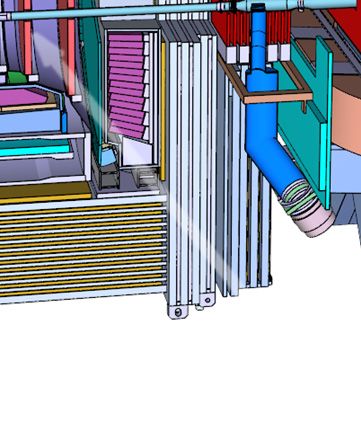
1.5 PANDA Infrastructure
[13] PANDA Collaboration. Technical Design Re- 20
The PANDA detector is located in an experimental port for the PANDA Muon System. 2013.
hall, encased in smaller tunnel-like concrete struc- [14] PANDA Collaboration. Technical Design Re-
10 ture for radiation protection. Most subsystems con- port for the PANDA Forward Tracker. 2017.
nect their FEE-components via cables and tubes
placed in movable cable ducts to the installations [15] A.Y. Barnyakov et al. Focusing aerogel RICH
in the counting house, where three levels are fore- (FARICH). Nuclear Instruments and Meth- 25
seen to accommodate cooling, gas supplies, power ods in Physics Research Section A: Accelera-
15 supplies, electronics, and worker places. Only sub- tors, Spectrometers, Detectors and Associated
components, where cables must be as short as possi- Equipment, 553(1):70–75, 2005.
ble, will place racks or crates directly on the outside
of the spectrometer. [16] PANDA Collaboration. TDR for PANDA For-
ward Time of Flight detector. 2018. 30
[17] O. Mineev et al. Photon sandwich detectors
Bibliography with WLS fiber readout. Nuclear Instruments
and Methods in Physics Research Section A:
20 [1] PANDA Collaboration. Technical Progress Re- Accelerators, Spectrometers, Detectors and As-
port, FAIR-ESAC/Pbar. 2005. sociated Equipment, 494(1):362–368, 2002. 35
[2] PANDA Collaboration. Physics Performance [18] PANDA Collaboration. Technical Design Re-
Report for PANDA: Strong Interaction Studies port for the PANDA Luminosity Detector. to
with Antiprotons. arxiv:0903.3905, 2009. be published.
25 [3] X. Liu. An overview of XYZ new particles. [19] K. Korcyl et al. Modeling event building ar-
arXiv:1312.7408v2 [hep-ph], 2014. chitecture for the triggerless data acquisiton 40
system for PANDA experiment at the HESR
[4] Yu. S. Kalashnikova et al. Quark and Meson facility at FAIR/GSI. Journal of Physics,
Degrees of Freedom in the X(3872) Charmo- 396(012027), 2012.
nium. Phys. Atom. Nucl., 73, 2010.
[20] M. Kavatsyuk. Sodanet specifications.
30 [5] K. Goetzen. Average Luminosities and Event https://panda-wiki.gsi.de/foswiki/ 45
Rates at PANDA. Report of the PID TAG, pub/FEE/SodaSpecifications/SODANET_
March 2009. specifications.pdf, 2013.8
2       Detector Control System Architecture

     2.1      Requirements and Design                         and alarms which should indicate clearly the source
                                                              of fault.
              Goals
                                                   Due to the long lifetime of the experiment the sys-
     The design of PANDA detector control system tem should be sustainable. This goal demands the
     (DCS) is the outcome of how the PANDA experi- usage, where is possible, of common hardware, open                5

5    ment is built, commissioned and operated:     source software and industry standards.

       • the experiment is assembled from sub-systems
         built by different institutions scattered all over   2.2     PANDA Online Systems
         the world
                                                                      Overview
       • the assembly is performed in stages
                                                          The PANDA detector is planned to be operated by
10     • the operation of the experiment should be effi- different online systems — Detector Control, Data          10

         cient and safe                                   Acquisition, Experiment Control — each of them
                                                          being designed to perform specific tasks (Fig. 2.1).
       • the experiment should communicate with other
                                                          The Detector Control System is designed to control
         online systems
                                                          and monitor the experimental equipment associated
       • the experiment should be operated by few peo- to PANDA sub-systems, and to exchange informa-               15

15       ple, non-experts, from a central control room    tion with other online systems, its main goal be-
                                                          ing the accurate, efficient and safe operation of the
       • the overall lifetime of the experiment is of the PANDA detector.
         order of decades.

     The PANDA DCS will have to monitor and control
     O 106 channels.


20   The above list is non-exhaustive so the first require-
     ment is the ease of expansion and scalablility in
     hardware and software.
     The second main requirement is a distributed
     system that should permit the autonomous oper-
25   ation of individual sub-systems during commission-
     ing, calibration or maintenance.
     While maintaining scalability and autonomy of the
     sub-systems the system should be consistent, the
     control and monitoring being performed from a cen-
30   tral software application, resulting from the integra-
                                                                  Figure 2.1: PANDA online systems flowchart
     tion of independently developed components at the
     level of sub-systems.
     The system should be highly available, with min- The DCS software at the sub-system level is divided
     imum down-times, and efficient in executing vari- in two categories, Front-End (FE) and Back-End               20
35   ous tasks at the device or network level.         (BE).
     The system should communicate with other PANDA Most of the FE software components — Graphical
     or external systems.                              Operator Interface layout and style, Finite State
     The central software application should have an in-      Machine interface, general purpose scripts — are
     tuitive and user-friendly Graphical User Inter-          going to be standardized, toolkits and generic tem-   25

40   face (GUI). Any malfunctioning of system compo-          plates, applicable to many sub-system’s needs, be-
     nents should be signaled to operators with warnings      ing made available in a dedicated DCS software
10
repository. This type of support coming from the The Run Control has a bidirectional communica-
DCS Core Group will positively reduce the soft- tion with the DCS, DAQ and Computing Control
ware development effort at sub-system level and System. It is responsible to send commands to the
also guarantee the DCS consistency. other systems and should receive operation param-
5 The sub-system DCS Back-End (BE) represents the eters from the DCS and information about abnor- 5
equipment’s — power supplies, pumps, sensors, flow mal behavior. The data acquisition should only
meters, actuators — and software components — be started by the run control, if the DCS reports
device drivers and high-level applications — used back that all subsystems are working and success-
to operate the detector and its associated services. fully configured.
10 Some PANDA sub-systems are well advanced in the In addition the ECS will be monitoring the other 10
implementation of controls, hardware and software online systems and receive all monitoring informa-
prototypes being already validated in beam or lab tion and status or alarm information from the DCS
tests. These prototypes, which already represents continuously.
a source of common solutions to be implemented The last part is dedicated to archive shift informa-
15 by other sub-systems, are going to be presented in tion, meta data from the data taking and configu- 15
more detail in Chapter 4. rations settings via an electronic logbook.
The PANDA DCS Core Group recommends the us- Details on the ECS and its working packages will
age of common hardware and software and will of- be the subject of a dedicated PANDA publication
fer support for the implementation of common so- after the completion of the technical design for all
20 lutions at sub-system level. However, it is the sub- PANDA online systems. In the present TDR the 20
system DCS experts responsibility to develop the concept and implementation of Finite-State Ma-
software components capable to ensure the correct chine (FSM) in the DCS framework are described
operation of the sub-system, to detect any local in Sec. 3.5.
anomalies, that can affect the sub-system hardware
25 and detector, and to guarantee the transition in a
safe state in case of emergency situations.
The experiment should exchange data with other 2.3 Hardware Architecture
“external” control systems of the PANDA Magnet,
HESR and FAIR. The interface with external sys- The hardware architecture of the PANDA DCS will 25
30 tems will be provided by the central DCS via Eth- be organized in a three layer stack — Supervisory,
ernet or field-bus, the exchanged data being in the Control and Field — as shown in Fig. 2.2.
form of states and commands or numerical values.
The highest level, Supervisory, is the level from
The data acquisition (DAQ) is dedicated to the where the overall control of the detector is go-
read-out of data acquired from the PANDA de- ing to be performed. The level will incorporate 30
35 tector channels via self-triggered front-end elec- workstations and servers with well defined roles as
tronic (FEE). The DAQ core features are hard- high-level control and monitoring of PANDA sub-
ware trigger-less, very precise timing using a com- detectors, database archiving, historical data re-
mon clock source, and data-reduction using online trieval and processing, interfacing with external sys-
software event filtering. tems. 35
40 The central DCS will have a reserved bidirectional External systems are the HESR, PANDA Magnets,
data-path to communicate with sub-systems while FAIR safety and access control and the Detector
the DAQ will communicate with the FEE via two Safety System. These systems are going to be man-
dedicated paths. One path, bidirectional, will be aged by a dedicated information dispatcher work-
used for the synchronization and configuration of station. The information flow will be bi-directional 40
45 the FEE through the SodaNet protocol.The second and accessible to all PANDA sub-systems, in order
path, unidirectional, from FEE to DAQ, is reserved to correlate with the external systems states.
for the detector digitized data.
The Control Layer and Field Layers are additionally
The Experiment Control System (ECS) is respon- divided in autonomous partitions corresponding to
sible with the coherent operation of PANDA dur- individual PANDA sub-detectors and sub-systems. 45
50 ing physics data-taking, being foreseen to perform These partitioning allows independent development
the overall control of data-taking per run. It can of controls for each sub-system, later integrated into
be divided into three main working packages: Run the central system, and a redundant distributed
Control, Monitoring and Logging. control system in case of central control failure.11
The Field Layer consists of all the devices — power (see sec. 3.6.2). The display can access the database
supplies, gas, cooling water, mechanical actuators, to show trends of certain data over a period of time.
etc — and sensors used to monitor and control the In order to ensure safe operation of the detector the
sub-system. These devices are spread all over the configuration of the subdetectors will be stored in a
5 experimental area and are all the operational ser- Configuration Database. Changing these configura- 5
vices which need to be provided for the detector. tion parameters is only allowed to the subdetector
The communication between supervisory hardware experts and not to a normal operator. Therefore
and control layer servers will be performed via Eth- the display part of the software also has an authen-
ernet network. Gateways are used to connect the tication module which restricts access to most write
10 autonomous partitions in the control layer to the su- commands to specific users. 10
pervisory layer. The connection between the gate-
way and the controllers will be also Ethernet based
while the connection with the field devices will be
performed mainly via industrial field-buses.
15 2.4 Software Components
The main software components are shown in fig. 2.3.
The I/O Controller will contain a Device Driver,
which communicates with a device in the Field
Layer. It acts as a bidirectional interface between
20 the device and the controller to read or write data.
From the Supervisory Layer commands can be send
to the controller. These commands can be divided
into two categories:
25 • discrete (low-level) , that can be executed di-
rectly by the controller;
• abstract (high-level), that should be converted
in a sequence of low-level commands.
Discrete commands read or write data directly via
30 the device driver. While abstract commands are in-
terpreted and processed by a Finite-State Machine
(FSM) which translates the abstract command into
multiple predefined read/write commands which
follow certain conditions. A simplified abstract
35 model of a FSM is shown in fig. 2.4. The concepts
of the finite state machine will be explained in more
detail in section 3.5.
The execution status for both type of commands
should be set by the controller.
40 A second main software component shown in figure
2.3 is the display, which will be used to visualize the
data from the field devices in a meaningful man-
ner, so that the operator can see and understand
the status of the detector, and can send the neces-
45 sary commands easily. In case an alarm is triggered
by a subdetector the operator will be informed via
the display. The data of the DCS as well as every
alarm will be stored in databases which are han-
dled by a Database Management System (DBMS)12
Figure 2.2: Conceptual drawing of the hardware architecture of the detector control system13
Figure 2.3: Conceptual drawing of the software architecture for the sub-detector control system.
Off
Error
Standby
Running
Figure 2.4: Abstract model of sub-detector, showing the finite states and transitions between them, that should
be implemented in the control system.14
3       Control System implementation

     3.1      Core Software Choice:                          easily.
              EPICS                                         The large user base has also led to the development
                                                            of many other tools that can connect to EPICS
                                                            via network and provide additional services like the
     The core software that was chosen for the PANDA graphical user interface (see Sec. 3.3.2), parame-               5
     DCS is the Experimental Physics and Industrial ter archiving software (see Sec. 3.6.3). In addition,
5    Control System (EPICS) framework.                      hardware vendors started to provide support for
     This section will present the reasons why the connecting their products to EPICS, thus eliminat-
     PANDA DCS group decided to use EPICS instead ing the need for custom device support development
     of one of its competitors, a detailed technical expla- (see Sec. 3.2.2).                                        10

     nation of EPICS, its components, and features will To provide access security, the network of the
10   follow in Sec. 3.2.                                    PANDA DCS will be split into several subnets,
     EPICS is an open source application[1] (see             which is possible due to the distributed nature of
     Sec. 3.2.9) under a BSD-like license. This not only     EPICS. Each PANDA subdetector will get its own
     means PANDA can use it without having to pay any        subnet (see Sec. 3.2.4) and any operation that re-      15

     license fees, but it also means that everybody can      quires expert knowledge or is potentially harmful
15   get access to the source code and has both the possi-   to the subdetector hardware can only be executed
     bility and the right to make modifications to EPICS     from within that subnet, so only persons from the
     if this is deemed necessary. Using open source soft-    specific subdetector groups having the proper au-
     ware also protects against the negative effects of      thorization will be able to initiate such commands.     20

     “vendor lock-in” where the customer is at the mercy     All detector information will be relayed to the su-
20   of his software vendor for good and for bad.            pervisory layer (see Sec. 2.3) via a read-only trans-
     EPICS runs under almost every operating system port. This enables the PANDA DCS to allow non-
     and can run on both high-power computer as well as expert operation by a small team in the control
     on small single-board computers with limited com- room: The people on shift will be able to see the             25

     puting resources[2] (see Sec. 3.2.3)                    complete status of the detector, but they cannot
                                                             accidentally cause any damage.
25   EPICS is used by accelerator centers and physics
     experiments all around the world and therefore has If used in conjunction with other open source soft-
     a large user base, an active development community ware, an EPICS-based DCS can provide failover
     and is proven to work properly[3]. The large user capabilities[4] (see Sec. 3.2.7), which means that the        30

     base and the vibrant community provide a very high tasks of a failing device are automatically trans-
30   likelihood that EPICS will be actively maintained ferred to another device or a backup device, this
     over the whole lifespan of the PANDA experiment. increases the operational security of the PANDA
                                                             detector and minimizes downtime due to technical
     An EPICS-based control system follows a dis- problems.                                                          35
     tributed architecture (see Sec. 3.2.3), so there will
     be many (small) computers running EPICS instead
35   of a large device being a single point of failure. This
     also allows an EPICS-based control system to meet
                                                             3.2 Technical Details of
     the goals laid out in Sec. 2.1 because the distributed           EPICS-based DCS
     architecture means that every PANDA subdetector
     can be tested autonomously and additional subde-
                                                             3.2.1 Introduction
40   tectors can be added over time.
     The distributed nature of EPICS and its efficient       EPICS is not a monolithic application, but it is a
     use of memory and network bandwidth also imply          tool set to create an individual control system for     40

     that an EPICS-based DCS is highly scalable. Be-         a specific detector or accelerator. EPICS has a dis-
     cause every computer running EPICS is only re-          tributed architecture centered around process vari-
45   sponsible for operating a small part of the DCS,        ables. “A Process Variable (PV) is a named piece
     the total distributed system can control and mon-       of data associated with the machine (e. g. status,
     itor several hundreds of thousands of parameters        readback, setpoint, parameter).” [3] Every PV has       45
16
a defined set of attributes like value, timestamp or age power supplies used by the EMC and the
alarm status. EPICS uses a client/server architec- LMD.
ture, with the addition that every server can also
act as client and connect to another server. In If no device support is available for a certain de-
5 the context of EPICS, there are several kinds of vice, one has to write the corresponding code.
servers like Input/Output Controllers (IOCs) and For the PANDA project, this was the case with 5
CA Gateways [2]. the high voltage power supplies made by iseg
Spezialelektronik GmbH. They can be controlled
An IOC is usually connected to the hardware of
via StreamDevice, but this has proven to be slow
the experiment that should be monitored and con-
and error-prone, so PANDA member Florian Feld-
10 trolled. This hardware includes power supplies, vac-
bauer has created a comprehensive device support 10
uum pumps, valves, front-end electronics, tempera-
for these power supplies in close collaboration with
ture sensors and cooling compressors. The connec-
the engineers from iseg (see Sec. 4.2.2).
tion between the IOC and the devices can be estab-
lished via a variety of interfaces like Ethernet, RS-
15 232, RS-485 and Controller Area Network (CAN) 3.2.3 EPICS IOCs
bus. Which one is chosen depends primarily on the
interfaces supported by the hardware vendor. The IOCs are the building blocks of an EPICS-
Each IOC makes all its information available on the based detector control system. They feature a 15
local network. The communication protocol used memory-resident database of all parameters of all
20 is a custom protocol developed for EPICS called devices assigned to them. Via the CA protocol,
Channel Access. Via Channel Access (CA), a client they can query data from any other IOC on the
can retrieve information, modify information and same network and provide their data to any client
ask to be informed about any new data for a specific on the network [2]. 20
PV. The software IOC (abbrev. SoftIOC) was origi-
nally developed to run under Wind River’s real-
time operating system vxWorks, but today it can
25 3.2.2 Device Support also run under any Unix-like operating system as
long as it provides POSIX compatibility. Within 25
The construction of an EPICS-based control sys-
PANDA, the IOCs will mostly run on Linux and
tem starts with a set of C/C++ code implementing
RTEMS machines. An IOC does not need much
a so-called “device support”. These routines enable
computing resources, so it runs flawlessly on low-
an EPICS IOC to talk to an individual piece of
power single-board computers like the Raspberry
30 hardware. For many devices, a generic device sup-
Pi1 or the BeagleBone Black2 . Both boards have 30
port written by members of the EPICS community
been successfully used during the construction of
can be used, so no programming work is necessary.
both the forward endcap EMC and the luminosity
Examples for these generic device support modules
detector. Real-Time Executive for Multiprocessor
are:
Systems (RTEMS)3 is an open source real time op-
erating system which will be used to operate the 35
35 • StreamDevice[5] can control any hardware with
FAIR DCS Board which is designed to be used in
a string-based sequential protocol. It can use
places with a high radiation flux where standard
any character-based communication protocol
boards like the Raspberry Pi would not work prop-
like a RS-232 serial line, USB-based serial line
erly (see Sec. 4.1.4).
or a TCP socket. StreamDevice has been used
40 within PANDA to control the cooling units for EPICS uses a custom build system based on GNU 40
the prototype (see Sec. 4.3) of the electromag- make which includes ready-to-use support for cross
netic calorimeter and the luminosity detector. compilation. Cross compilation is the process of
converting source code into an executable that is
• devModbus[6] implements all three specifica- designed to run on a different processor architec-
tions of the ModBus standard (ModBus RTU, ture than the processor on which the build system 45
45 ModBus ASCII and ModBus TCP). It is used is running. This way, an EPICS IOC can also be
to control the pumps and the cooling compres- operated on embedded devices that do not provide
sor of the EMC. the means to run a compiler themselves.
• devSNMP[7] can operate any device accessi- 1. https://www.raspberrypi.org/
ble via the Simple Network Message Proto- 2. https://beagleboard.org/black
50 col (SNMP), e. g. the Wiener PL-512 low volt- 3. https://www.rtems.org/Sie können auch lesen