DIMAX DIGITALZENTRALE DIMAX CENTRAL STATION - 800Z, 1210Z
←
→
Transkription von Seiteninhalten
Wenn Ihr Browser die Seite nicht korrekt rendert, bitte, lesen Sie den Inhalt der Seite unten
DiMAX Digitalzentrale
DiMAX Central Station
        800Z, 1210Z
               8136001, 8136501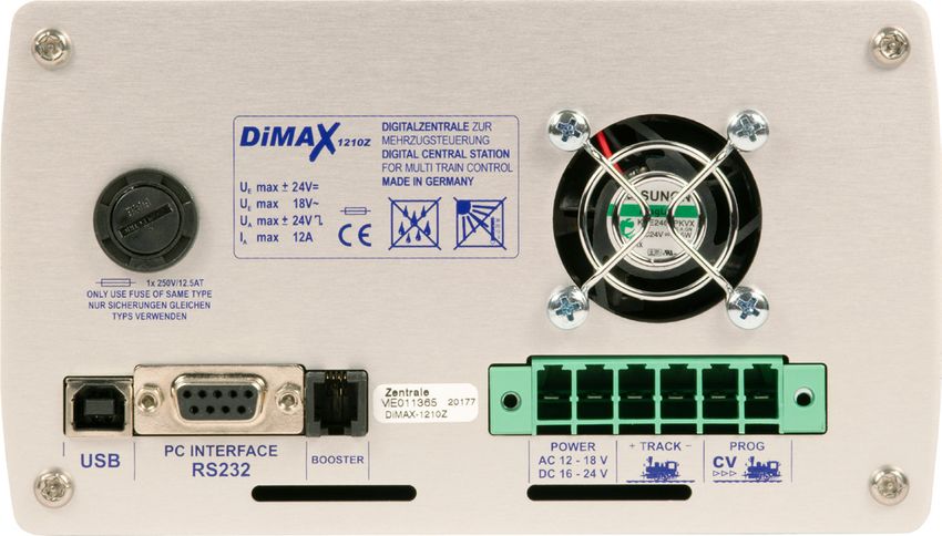
Inhaltsverzeichnis                                                                Table of Contents
Beschreibung..........................................................            General Description..................................................               4
Übersicht Funktionsumfang....................................                     Summary of Functions.............................................                   4
Übersicht Systemanschlüsse..................................                      Layout of Terminals..................................................               5
Lieferumfang...........................................................           Scope of Supply.......................................................              5
Inbetriebnahme.......................................................             Starting Up...............................................................          6
Anschluss...............................................................          Connection...............................................................           6
Display & Tastatur..................................................              Display and Keyboard...............................................                 8
Status LEDs............................................................           Status LEDs.............................................................            8
Anschluss der Steuerkomponenten........................                           Connecting the Input Devices...................................                     9
Erstes Einschalten...................................................             First Switch-on.........................................................            9
Das Display.............................................................          The Display..............................................................          10
Menüsteuerung.......................................................              Menu Prompting......................................................               10
Die NOT-STOP Taste...............................................                 The Emergency Stop Key.........................................                    11
MENÜ-Übersichtsdiagramm...................................                        Menu flow chart.......................................................             12
Sicherungen............................................................           Fuses........................................................................      14
RS 232 + USB Anschluss........................................                    RS 232 + USB Ports.................................................                14
Einführung in die Digitalsteuerung mit DiMAX                                      Introduction to Digital Control with DiMAX Digital
Digital.....................................................................      ................................................................................   14
Datenbank für 128 Lokdaten...................................                     Database for 128 Locomotives.................................                      14
Lokadresse..............................................................          Locomotive Address................................................                 15
Fahrstufen...............................................................         Speed Steps.............................................................           15
Art der Funktionsauslösung....................................                    Producing Special Functions....................................                    15
Parallele Funktionsauslösung.................................                     Producing Parallel Functions....................................                   15
Serielle Funktionsauslösung...................................                    Producing Serial Functions......................................                   16
Anzahl gleichzeitig steuerbarer Loks.......................                       Number of Locomotives in Simultaneous Operation                                    16
Betriebseinstellungen..............................................               Operational Settings.................................................              17
Maximaler Fahrstrom..............................................                 Maximum Driving Current........................................                    17
Lokabmeldung für Buswandlerbetrieb                                                How to log off Locomotives when using a DiMAX
...............................................................................   Transducer...............................................................          18
Abschaltzeit bei Kurzschluss...................................                   Turn Off Time in Case of Short Circuit.....................                        18
Maximale Anzahl aktiver Loks................................                      Maximum Number of Active Locomotives...............                                19
Funktionsdaten ab F9.............................................                 F-Functions beyond F8.............................................                 20
Spannungseinstellung............................................                  Track Voltage Adjustment........................................                   21
Erweiterte Systemeinstellungen..............................                      Advanced System Settings......................................                     21
Automatikeinstellungen..........................................                  Settings of the Automatic Functions........................                        21
Betriebszustand der aktiven Loks speichern...........                             Save the Status of Active Locomotives....................                          21
Betriebszustand der aktiven Loks rücksetzen.........                              Reset Status of Active Locomotives.........................                        22
Automatikfunktionen speichern..............................                       Store Automatic Functions.......................................                   23
Automatikfunktionen rücksetzen.............................                       Reset Automatic Functions.......................................                   24
Lokdatenbank löschen (Dauer ca. 30 Sekunden)....                                  Delete Locomotive Data Base (takes 30 sec)...........                              24
Systemeinstellungen...............................................                System Settings.......................................................             25
Sprache...................................................................        Language.................................................................          25
Firmwareupdate......................................................              Firmware Update......................................................              26
Systemdaten...........................................................            System Information..................................................               26
LGB® MZS II Komponenten an der DiMAX Digi-                                        Using LGB® MTS II Components with the DiMAX
talzentrale...............................................................        Central Station..........................................................          27
Funktionsweise des DiMAX 600A Buswandlers......                                   Operating Mode of the DiMAX® 600A Transducer..                                     27
Fahrstufenskalierung im Buswandler                                                Managing Speed Steps in the DiMAX® 600A
...............................................................................   Transducer...............................................................          27

2                                                                        DiMAX 1210Z, 800Z
Erweiterte Funktionen.............................................                Advanced Functions.................................................              27
Vorführmodus für Demonstrationsanlagen............                                Demonstration Mode...............................................                28
Automatikfunktionen..............................................                 Automatic Functions................................................              29
Softwareupdate......................................................              Softwareupdate........................................................           30
Verbindung zwischen PC und DiMAX Digitalzen-                                      Connect your PC to the DiMAX Central Sta-
trale herstellen........................................................          tion..........................................................................   30
Via RS 232.............................................................           Connecting via the RS 232 port...............................                    30
Via USB..................................................................         Connecting via the USB port....................................                  30
Updateprogramm...................................................                 Update Program.......................................................            31
Gerätefirmware.......................................................             Software of DiMAX Components..............................                       31
Updatemodus der Digitalzentrale starten                                           Start the Update Function of the DiMAX Central
...............................................................................   Station......................................................................    31
Update durchführen................................................                Execute the Update..................................................             32
Tipps & Tricks........................................................            Useful Hint...............................................................       35
Technische Daten...................................................               Technical specifications...........................................              36
Garantie, Reparatur, Kundendienst.........................                        Warranty, Service, Support......................................                 37
Hotline....................................................................       Hotline......................................................................    37
Glossar....................................................................       Glossary...................................................................      38

                                                                      DiMAX 1210Z, 800Z                                                                            3
WICHTIG: Glockenankermotoren dürfen nicht im             Important: Coreless motors must not be used in
 Analogbetrieb gefahren werden! Diese werden da-          analog mode! This type of motors will be severely
 durch zerstört! Für Schäden durch unsachgemäße           damaged! Massoth is not responsible for dam-
 Einstellung übernehmen wir keine Haftung!                ages resulting from improper settings.

    Bitte lesen Sie diese Bedienungsanleitung vor           Please read this Manual thoroughly before oper-
    Inbetriebnahme gründlich durch.                         ating your DiMAX Central Station

1. Beschreibung                                          1. General Description
   Die DiMAX 800Z / 1210Z Digitalzentrale ist die op-       The DiMAX 1210Z Central Station is the optimum
   timale Gartenbahnzentrale für Modellbahnanlagen          choice for Garden Railroaders. It is the best
   mit höchsten Anforderungen. Sie vereint kraftvolle       combination of a powerful 12 Amps driving cur-
   8 bzw. 12 Ampere Fahrstrom mit hohem Sicher-             rent, high safety standards and up to date high end
   heitsstandard und zukunftsweisender Technologie.         technology.
   Auf Basis des NMRA / DCC Systems steuert die             Based on the NMRA Standard the DiMAX 1210Z
   DiMAX 800Z / 1210Z Digitalzentrale Lokmodelle            Central Station controls Locomotives equipped
   mit Dekodern von allen bekannten Herstellern. Als        with decoders of all major manufacturers. A unique
   eines der wenigen Digitalsysteme kann die DiMAX          feature is the ability to produce digital and analog
   800Z / 1210Z sowohl parallele als auch serielle          signals which enables the DiMAX 1210Z to operate
   Funktionsdaten senden und damit auch Loks älterer        locomotives equipped with older sound modules.
   Soundgenerationen ansteuern. Ein Umbau dieser            A conversion of old models is therefore not neces-
   Modelle ist daher nicht notwendig.                       sary.

1.1 Übersicht Funktionsumfang                            1.1 Summary of Functions
  • DiMAX 1210Z: 12 Ampere Fahrstrom                       • DiMAX 1210Z: max 12 Amps Driving Current
    (per Menü einstellbar in 4 / 7 und 12 Ampere)            (adjustable to 4, 7 and 12 Amps)
  • DiMAX 800Z: 8 Ampere Fahrstrom                           DiMAX 800Z: max 8 Amps Driving Current
    (per Menü einstellbar in 2, 4 und 8 Ampere)              (adjustable to 2, 4 and 8 Amps)
  • Betriebsspannung extern ca. 16 - 24 Volt Gleich-       • External Supply Voltage 16 V to 24 V DC or
    spannung (begrenzt auf max. 24= Volt)                    12 V to 18 V AC
    oder 12 - 18 Volt Wechselspannung                      • Separate Programming Outlet
  • separater Programmiergleisanschluss                    • Voltage Limitation
  • Spannungsbegrenzung                                      (Driving Voltage limited to 22 V DC)
    (Fahrspannung wird auf 22 Volt begrenzt)               • Adjustable Turn Off Time in case of short circuit
  • Abschaltzeit einstellbar bei Kurzschluss                 (between 0.1 and 0.8 sec)
    (einstellbar von 0,1 bis 0,8 Sekunden)                 • Integrated Fan (Temperature Controlled)
  • Lüfter fest integriert (temperaturgesteuert)           • LCD Display (White Letters with Blue Background
  • LCD Display (weiße Schrift auf blauer Hintergrund        Lighting)
    beleuchtung)                                           • Compatible to NMRA DCC
  • NMRA DCC kompatibel                                    • Compatible to LGB® MTS
  • LGB® MZS kompatibel                                    • Parallel and Serial Data Processing
  • parallele und serielle Funktionsdatenverarbeitung      • Booster Interface
  • Boosterschnittstelle (zur Erweiterung)                 • PC Interface (Protocol available for free)
  • offene Schnittstelle für PC-Steuerung                  • Track Voltage Adjustment
    (Protokoll frei erhältlich)
  • Einstellbare Versorgungsspannung

4                                             DiMAX 1210Z, 800Z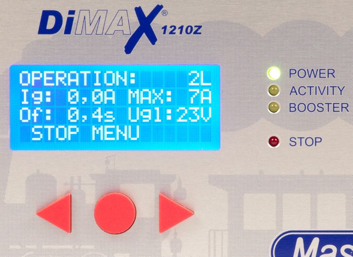
Systemeigenschaften:                                      System Properties:
 •   10239 Lokadressen                                     •   10239 Locomotive Addresses
 •   14 / 28 / 128 Fahrstufen                              •   14/28/128 Speed Steps
 •   2048 Weichenadressen                                  •   2048 Switch Addresses
 •   2048 Rückmeldeadressen                                •   2048 Feed Back Addresses
 •   Datenbank für 128 fertig konfigurierte Loks           •   Data Base of 128 Preconfigured Locomotives
     (Eingabe durch Handregler)                                (Input with handheld Controller)
 •   32 Loks gleichzeitig steuerbar                        •   32 Locomotives simultaneously controllable
 •   Automatikbetrieb ohne PC                                  (other systems do 8 or 12 Locos)
     (direkt per Rückmelder oder Belegtmelder)             •   Automatic Function without PC (using Feedback
 •   CV Schreiben (direkt / indirekt)                          Interface and Train Detection Module)
 •   CV Lesen                                              •   Write CV (direct/indirect)
 •   Register-Programmierung                               •   Read CV
 •   POM (Program on Main / Programmieren auf dem          •   Register Programming
     Fahrgleis)                                            •   PoM (Program on Main / Programming on Track)
 •   LGB® MZS Komponenten                                  •   LGB® MTS Components usable (via Transducer)
     (z.B. Lokhandy, etc. über Buswandler nutzbar)         •   Automatic Speed Step Scaling (14/28/128) with
 •   automatische Fahrstufenskalierung (14 / 28 / 128)         LGB® Components
     bei LGB® MZS Komponenten
 Hinweis: Der Funktionsumfang der DiMAX 1210Z Di-          Note: The functional range of the DiMAX 1210Z
 gitalzentrale wird regelmäßig erweitert. Anregungen       Central Station is being updated on a
 werden gerne entgegen genommen. Die Funktions-            regular basis. Suggestions are welcome. The DiMAX
 erweiterungen können durch ein Firmwareupdate der         1210Z Central Station can be easily kept up to date
 Zentrale jederzeit aufgewertet werden.                    using the Update Function.

1.2 Übersicht Systemanschlüsse                            1.2 Layout of Terminals
  • externe Spannungsversorgung (16V - 24V Gleich-          • External Power Supply (16 V to 24 V DC or 12 V to
    spannung oder oder 12 - 18 Volt Wechselspan-              18 V AC) separately fused
    nung) mit separater Sicherung                           • 3 Bus Outlets on the Front (e.g. for Handheld
  • 3 x Steuerkomponentenanschlüsse (Frontseite /             Controller)
    z.B. Handregler, Funkempfänger, etc...)                 • Track Power Terminal
  • Fahrgleisanschluss                                      • Program Terminal
  • Programmiergleisanschluss                               • Booster Interface (on the back)
  • Boosterschnittstelle (Rückseite)                        • PC Interface RS232 + USB
  • PC Interface RS232 + USB                                  (for Updates and PC- Controlling)
    (für Updates, PC-Steuerung, etc...)

     Die Anschlussbuchsen für DiMAX Steuerkompo-               The bus outlets for handheld controllers, RC receiv-
     nenten, wie z.B. Handregler, Funkempfänger, Rück-         ers, feedback modules etc. may be
     melder, Belegtmelder, etc. können jederzeit über          extended by an additional DiMAX Adapter (Item No.
     einen zusätzlichen Verteiler (DiMAX Busverteiler          8138001).
     Art.Nr.: ME 8138001) erweitert werden.

1.3 Lieferumfang                                          1.3 Scope of Supply
  • DiMAX Digitalzentrale                                   • DiMAX Central Station
  • Komponentenstecker zum Anschluss für Fahr- und          • Multi-Connector (to connect track power, program-
    Programmiergleis sowie externe Spannungsver-              ming track and external power source)
    sorgung                                                 • Manual
  • Handbuch

                                             DiMAX 1210Z, 800Z                                                   5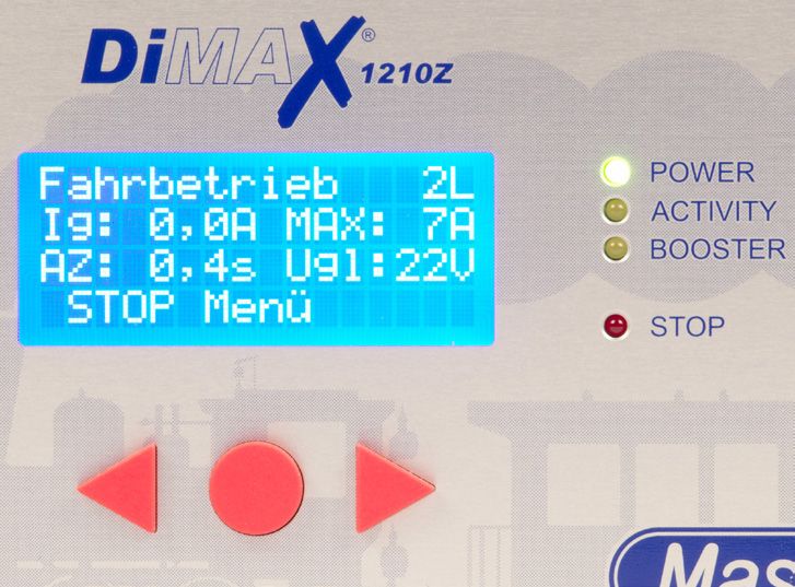
Sollte eine dieser Positionen im Lieferumfang nicht In case any of these items is missing or damaged
enthalten oder beschädigt sein, so informieren Sie contact your local dealer or the manufacturer.
bitte Ihren Fachhändler oder wenden Sie sich direkt
an den Hersteller.
Hinweis: Bitte bewahren Sie den Karton und die Note: Please keep your box and the Styrofoam parts,
zwei Styroporkopfteile zur Aufbewahrung Ihrer to ensure proper packaging in case of shipping. If
Zentrale und zum Transport auf. Die Digitalzentrale dropped, the DiMAX Central Station can be damaged
kann durch Sturz nachhaltig beschädigt werden. significantly.
2. Inbetriebnahme 2. Starting Up
Das folgende Kapitel widmet sich der ersten Inbe- The chapters below will guide you through the set
triebnahme der DiMAX Digitalzentrale. Gehen Sie up and first operation of your DiMAX Central Sta-
dazu bitte wie folgend beschrieben vor. tion. Please follow every step closely.
2.1 Anschluss 2.1 Connection
Nehmen Sie die Digitalzentrale aus der Verpackung Take your DiMAX Central Station out of the box
heraus. Stellen Sie die Zentrale an einen dafür ge- and position it in an appropriate place. The Central
eigneten Platz. Wegen der Wärmeentwicklung, soll- Station should not be placed close to a radiator,
te die Zentrale nicht in der Nähe eines Heizkörpers any other heater or in direct sunlight to ensure
positioniert oder auch direkter Sonneneinstrahlung sufficient ventilation and temperature range for the
ausgesetzt werden. DiMAX Central Station.
Der Lüfter auf der Rückseite sowie die Luftan- The ventilation outlet is on the back side and it
saugöffnungen müssen jederzeit frei bleiben und should be kept clear of any
dürfen nicht blockiert werden. obstructions at all times.
Nehmen Sie den grünen Anschlussstecker aus der Use a screw driver to connect the power cable from
Packung der Digitalzentrale heraus. Verwenden Sie the track as well as the power source to the con-
einen Schraubendreher um das Anschlusskabel nector of the central station (see illustration #3).
Ihres Fahrgleises und die Kabel der Versorgungs- Make sure to use the correct terminals. The polarity
spannung in die korrekten Buchsen des Steckers is not important.
zu schrauben (Abb. 3). Die Polarität der Eingangs-
spannung ist unerheblich. Stecken Sie den Stecker
anschließend in die dafür vorgesehene grüne
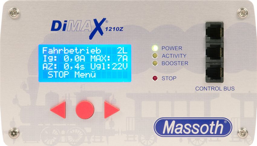
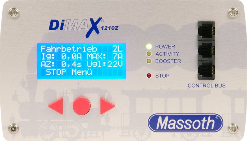
Status-Led‘s
Display
Control Bus
Funktionstasten
Function Keys
Abbildung 1: Die Frontansicht der DiMAX 1210Z (identisch mit DiMAX 800Z)
Illustration #1: Front view of the DiMAX 1210Z (similar to DiMAX 800Z)
6 DiMAX 1210Z, 800Z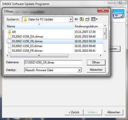
Buchse auf der Rückseite der Digitalzentrale.

                                                                                                Lüfter
                      Sicherung                                                                  Fan
                         Fuse

                                            Seriennummer
                                            Serialnumber

                       PC-Interface Booster Hauptanschluss-Stecker
                       USB RS232 Interface     Multi Connector
Abbildung 2: Die Rückansicht der DiMAX 1210Z (identisch mit DiMAX 800Z)
Illustration #2: Rear view of the DiMAX 1210Z (identical with DiMAX 800Z)
                                                           Hauptanschlussstecker
                                                              Multi connector
                                                           Sicht v. hinten / Back side
                                                                 Fahrgleis / Track Power

                                             Externer
                                                                                                       Programming track
                                                                                                       Programmiergleis

                                   Spannungsversorgungseingang
                                        12-18V~/16-24V=
                                          bei ca. 350 VA

                                         External power
                                        12-18V~/16-24V=
                                         at appr. 350 VA

Abbildung 3: Steckeranschluss
Illustration #3: Wiring diagram

 WICHTIG: Fahrgleis und Programmiergleis dürfen
                                                                                           IMPORTANT: Track power and program power
 elektrisch nicht verbunden sein!
                                                                                           must never be connected.

                                             DiMAX 1210Z, 800Z                                                                        7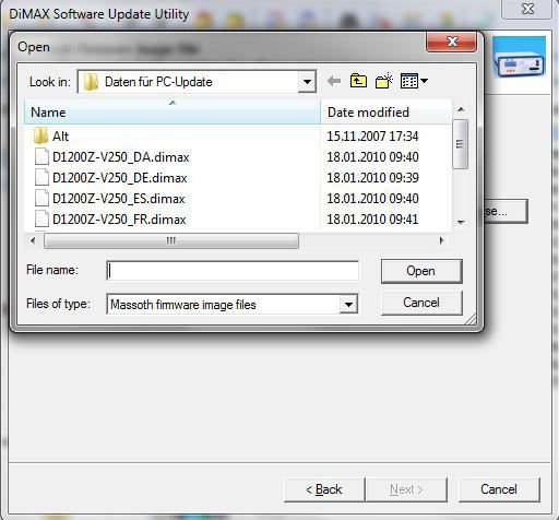
2.2 Display & Tastatur                                    2.2 Display and Keyboard
   Das Display informiert im Betrieb jederzeit über den      The display shows important information regarding
   aktuellen Zustand der Anlage (Abb. 4). Wichtige           the operation of your DiMAX Central Station at all
   Daten, wie z.B. die momentane Auslastung in Am-           times:
   pere, die Anzahl der aktiven Loks, der eingestellte       Number of active locomotives, present current load
   maximale Fahrstrom (12 Ampere bzw. wie einge-             (Amps), maximum Amps (12 Amps or as selected),
   stellt), die Abschaltzeit bei Kurzschlusserkennung        turn off time in case of short circuit (as selected)
   und die gemessene Fahrspannung (22 Volt) werden           and the measured driving voltage.
   immer aktuell angezeigt.                                  Use the three keys below the display to navigate
   Mit den drei Tasten unter dem Display navigieren          through the menu. The lower line in the display
   Sie durch das Menü der Digitalzentrale. Dabei             shows the assignments of the keys and the func-
   zeigt die unterste Zeile des Displays die Belegung        tion respectively.
   der Tasten, abhängig von der entsprechenden
   Menüfunktion.

Abbildung 4: Display im Fahrbetrieb
Illustration #4: Display in operation mode

2.3 Status LEDs                                           2.3 Status LEDs
   Die Zentrale verfügt an der Frontseite über 4 LEDs        4 LEDs show the state of operation of your DiMAX
   die den Zustand der Zentrale anzeigen.                    Central Station:
 Power-LED        Nach dem Starten der Zentrale und        Power LED       After switch-on and after the
 (grün)           erfolgreichem Abschluss des Sys-         (green)         successful internal test the DiMAX
                  temtests befindet sich die Zentrale                      1210Z Central Station switches into
                  im Fahrbetrieb. Die Power-LED                            normal driving mode. The power
                  leuchtet dabei dauerhaft.                                LED is steadily illuminated.
 Aktivitäts-LED   Die Aktivitäts-LED blinkt im Betrieb     Activity LED    The activity LED is blinking when
 (gelb)           wenn durch die Steuerkomponen-           (yellow)        data is being processed and sent
                  ten Befehle erfolgen. Beim Empfang                       to components. In case of software
                  von Firmwareupdates einer Kompo-                         update this LED will blink during
                  nente blinkt die LED beim Empfang                        reception of data.
                  der einzelnen Datenpakete vom PC.
                                                           Booster LED     The booster LED is illuminated if a
 Booster-LED      Die Booster-LED leuchtet, wenn ein       (yellow)        booster is connected to the DiMAX
 (gelb)           Booster an der Boosterschnittstelle                      1210Z Central Station and the data
                  angeschlossen ist und der Daten-                         transfer between these components
                  austausch korrekt stattfindet.                           is working correctly.

8                                              DiMAX 1210Z, 800Z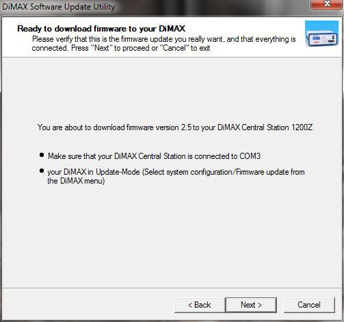
STOP-LED         Die STOP-LED blinkt, bzw. leuchtet,       STOP LED        The STOP LED blinks or is illumi-
 (rot)            wenn über die Zentrale oder ein           (red)           nated if an emergency stop had
                  Steuergerät bzw. Rückmeldekon-                            been initiated by the DiMAX Central
                  takt der NOTSTOP ausgelöst wird.                          Station or other components.

2.4 Anschluss der Steuerkomponenten                        2.4 Connecting the Input Devices
   Die DiMAX Digitalzentrale verfügt an der Frontseite        The DiMAX Central Station features four recep-
   über 3 Anschlussbuchsen für Steuerkomponenten              tacles for devices such as the DiMAX Navigator
   wie z.B. den DiMAX Navigator, DiMAX Buskom-                and other DiMAX Components such as the DiMAX
   ponenten, wie z.B. Rückmelder und Belegtmelder,            Feedback Interface, the DiMAX Train Detection
   sowie den DiMAX Buswandler zum Anschluss der               Module, a Switch Decoder or the DiMAX Trans-
   LGB® MZS II Steuer- und Buskomponenten.                    ducer for MTS II Bus Components. After the
   Die DiMAX Digitalzentrale wird nach dem erfolgrei-         completion of the internal system test the DiMAX
   chen Systemtest den Steuerbus (gekennzeichnet              Central Station will power up the control bus.
   mit CONTROL BUS) aktivieren. Angeschlossene                Peripheral components connected to this bus will
   Komponenten nehmen daraufhin den Betrieb mit               start working.
   der Zentrale auf.

3. Erstes Einschalten                                      3. First Switch-on
   Nach dem ersten Einschalten sehen Sie am Display           After the switch-on the Central Station starts boot-
   nacheinander 3 verschiedene Anzeigen. In der letz-         ing and displays three indications one after another.
   ten Anzeige wird Ihnen für einige Sekunden unten           The last indication displays the serial number and
   die Seriennummer und der aktuelle Firmwarestand            the current software installed (Illustr. #5).
   der DiMAX angezeigt (Abb. 5).

Abbildung 5: Bootvorgang
Illustration #5: Indications during booting

                                              DiMAX 1210Z, 800Z                                                   9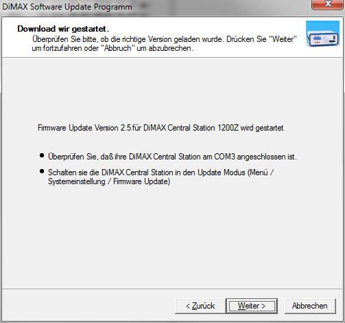
3.1 Das Display                                            3.1 The Display
   Nach dem Bootvorgang wird Ihnen das Fahr-                  After booting the DiMAX Central Station displays
   betriebsmenü angezeigt. Hier haben Sie eine                the main menu window for driving operation (Il-
   Übersicht aller Grunddaten (Abb. 6).                       lustr. #6):

Abbildung 6: Fahrdisplay
Illustration #6: Driving operation

3.2 Menüsteuerung                                          3.2 Menu Prompting
   Die Einstellungen für das Digitalsystem werden             The settings of the digital system are accomplished
   im Menü der Zentrale vorgenommen. Es stehen                in the menu of the Central Station. Several options
   verschiedene Einstellungsoptionen zur Verfügung.           are available. Open the menu by pressing the red
   Mit der runden, roten Taste (hier bezeichnet mit           round button marked “menu”. Use the three but-
   MENÜ) öffnen Sie das Menü der Zentrale. Nutzen             tons to navigate through the menu to adjust the
   Sie alle drei Tasten, abhängig von Ihrer Belegung          settings (Illustr. #7).
   zum Navigieren durch das Menü und zum Einstel-
   len der entsprechend gewünschten Funktionen
   (Abb. 7).

                            Zeile für Funktionstastenbelegung
                            Function key assignments

                               Funktionstasten
                                Function Keys
Abbildung 7: Menüsteuerung
Illustration #7: Menu Prompting

10                                           DiMAX 1210Z, 800Z
3.3 Die NOT-STOP Taste 3.3 The Emergency Stop Key
Möchten Sie den Strom am Gleis schnell unter- There are several options to initiate an emergency
brechen, gibt es hierzu mehrere Möglichkeiten. An stop. At the Central Station (Illustr. #8+9):
der Zentrale (Abb. 8+9): Sie können aber auch die The same functions are available with a DiMAX
STOP Taste am Navigator oder am LGB®-Handy Navigator or the LGB Remote Control.
benutzen.
Abbildung 8: Auslösung Not-Stop Illustration #8: Emergency Stop
Abbildung 9: Aufhebung Not-Stop Illustration #9: Cancel emergency stop
DiMAX 1210Z, 800Z 114. MENÜ-Übersichtsdiagramm 12 DiMAX 1210Z, 800Z
4. Menu flow chart

                     DiMAX 1210Z, 800Z   13
5. Sicherungen 5. Fuses Die DiMAX Digitalzentrale wird über eine externe The DiMAX Central Station will be powered by an Spannungsquelle betrieben. Dafür ist eine Si- external power source. The 12 AT fuse are acces- cherung mit 12AT auf der Rückseite des Geräts sible on the back side of your DiMAX 1210Z Central integriert. Station (See Illustr. #11). 5.1 RS 232 + USB Anschluss 5.1 RS 232 + USB Ports Auf der Rückseite finden Sie auch einen RS 232 On the back side you find an RS 232 and an USB und USB Anschluss. (Abb. 2) port. (Illustration 2) Es ist nur einer von beiden nutzbar, schließen Sie You may use either port but not both at the same nicht beide gleichzeitig an Ihren PC an. Dieser time. Both ports connect to your PC to either Anschluss dient dazu um via PC Ihre Anlage zu control your layout by PC or do firmware updates steuern oder um Firmwareupdates durchzuführen. (check Chapter 10). Mehr dazu in Kapitel 10. 5.2 Einführung in die Digitalsteuerung 5.2 Introduction to Digital Control mit DiMAX Digital with DiMAX Digital Das DiMAX Digitalsystem entspricht dem NMRA The DiMAX Digital System complies with the DCC Standard. Damit können alle Digitalkompo- NMRA DCC Standard. All digital components that nenten, die nach NMRA DCC arbeiten, gesteuert comply with this standard may be operated with the werden. Darüber hinaus versteht die DiMAX die DiMAX Central Station. The DiMAX Central Station Sonderfunktionen des LGB® MZS Digitalsystems works with the special functions of the LGB® MTS und kann diese gleichzeitig mit den Befehlen nach System and NMRA compatible components on the NMRA DCC auf dem Fahrgleis verarbeiten. same track. 5.3 Datenbank für 128 Lokdaten 5.3 Database for 128 Locomotives Ein wesentlicher Vorteil des DiMAX Digitalsystems One of the prominent benefits of the DiMAX Digital ist die dauerhafte Speicherung Lokbezogener Da- System is the ability to store locomotive data per- ten. Dabei werden in der Zentrale die Einstellungen manently such as address, speed step configura- der Lokadresse, Fahrstufenkonfiguration, Funkti- tion, special functions, and the pictogram. These onsauslösung und das Lokbild gespeichert. Diese data are made available to all DiMAX Navigators or Daten stehen allen Handgeräten, die an der Zentrale other handheld controllers connected to the DiMAX angeschlossen sind, zur Verfügung. Nach dem Central Station. This data is available after every Einschalten des Systems sind diese Daten wieder power up and will not be lost after shut down. The vorhanden. Der Lokname wird anwenderbezogen names of the locomotives are generally user related im Handy gespeichert. Die integrierte Datenbank and therefore stored in the handheld controller speichert die Daten von bis zu 128 Lokomotiven only. The integrated database stores up to 128 dauerhaft in der Zentrale ab. Es wird keine umwelt- locomotives permanently. All relevant locomotive schädliche Batterie zur Pufferung benötigt! data is shown immediately after the respective Wird eine dieser gespeicherten Loks von einem address has been put in a DiMAX Navigator. The Handregler aufgerufen, so sind die Informationen address, speed steps, special functions, and picto- über Lokadresse, Fahrstufen, Funktionsauslösung gram are displayed here. The locomotive is ready to und Lokbild sofort auf dem Display des Handreg- drive without any further actions. The only thing for lers zu sehen. Für den Betrieb müssen damit kei- you to do is: select and load the locomotive. nerlei Einstellungen mehr vorgenommen werden. Das Laden der Lok genügt. 14 DiMAX 1210Z, 800Z
5.4 Lokadresse                                            5.4 Locomotive Address
   Im DiMAX Digitalsystem wird jede Lok mit einer            The DiMAX Digital System identifies each locomo-
   Lokadresse (Zahl von 1 bis 10239) benannt. Dabei          tive by an address (Number 1…10239). The
   sind die Adressen 1 bis 9999 für reguläre Lokad-          numbers 1…9999 are used for regular locomotive
   ressen vorgesehen.                                        addresses.

5.5 Fahrstufen                                            5.5 Speed Steps
   Die Digitalzentrale unterstützt die im NMRA DCC           The DiMAX Central Station supports the usual
   üblichen 14, 28 und 128 Fahrstufen. Die Anzahl der        14, 28 and 128 speed steps defined by the NMRA
   Fahrstufen stellt die Einteilung der Motorspannung        DCC Standard. The speed steps define by which
   in kleinen Stufen von Fahrstufe 0 (Lok steht) bis         number the maximum driving current is divided.
   maximale Fahrstufe (maximale Geschwindigkeit)             Using lower numbers result in a slow speed, the
   dar. Ein Decoder, gesteuert mit 14 Fahrstufen, wird       higher numbers result in faster speeds. A decoder
   den Motor mit 14 Spannungsstufen je Richtung              programmed for 14 speed steps will control the lo-
   regeln. Bei 28 Fahrstufen sind es 28 Spannungs-           comotive in 14 voltage steps in every direction. 28
   stufen je Richtung bei 128 Fahrstufen respektive          speed steps provide 28 voltage steps, 128 speed
   128 Spannungsstufen. Für den Gartenbahnbereich            steps 128 voltage steps respectively. For G-Scale
   empfehlen sich in der Regel 28 Fahrstufen.                Garden Railroading we recommend 28 speed steps.
   Erfolgt die Konfiguration einer Lokomotive nicht,         In case no configuration of the locomotive has
   wird sie über den DiMAX Navigator automatisch             been done, the DiMAX Navigator automatically
   mit 28 Fahrstufen, mit LGB® MZS II Komponenten            configures the locomotive to 28 speed steps. Using
   über den Buswandler automatisch mit 14 Fahrstu-           LGB® Components in combination with a DiMAX
   fen betrieben.                                            Transducer the locomotive will be controlled with
   (Siehe Kapitel 8 – LGB® MZS II Komponenten an             14 speed steps automatically.
   der DiMAX Digitalzentrale)                                (See chapter 8 – LGB® MTS II Components with
                                                             the DiMAX Central Station)

 HINWEIS: Beachten Sie, dass bei Lokomotiven mit           Please note that in locos configured in 14 speed
 konfigurierten 14 Fahrstufen, das Licht nicht korrekt     steps the light will not display correctly if they are
 funktioniert, wenn sie mit 28 Fahrstufen angesteuert      controlled with 28 speed steps. The same is true for
 werden. Das gleiche gilt für Lokomotiven die auf 28       locos defined for 28 speed steps that are controlled
 Fahrstufen eingestellt sind jedoch mit 14 Fahrstufen      with 14 speed steps. In these cases the lights of the
 angefahren werden.                                        locomotives may flicker or may not work at all.

5.6 Art der Funktionsauslösung                            5.6 Producing Special Functions
   Im DiMAX Digitalsystem werden parallele und seri-         The DiMAX Digital System provides two kinds of
   elle Funktionsauslösung unterstützt. Die Einstellung      function triggering: parallel and serial. The selection
   erfolgt bei der Konfiguration der Lokeigenschaften        of the respective technique is made during the
   über den Handregler.                                      locomotive configuration via the DiMAX Navigator
                                                             or any other handheld controller.

5.6.1 Parallele Funktionsauslösung                        5.6.1 Producing Parallel Functions
   Die parallele Funktionsauslösung ist die standar-         Parallel function triggering is standard in the NMRA
   disierte Funktionsauslösung nach NMRA DCC.                DCC operation. Each function command is sent to
   Dabei wird der direkte Funktionsbefehl an die Lok         the locomotive directly. Pushing the F1 key releases
   übertragen. Die Funktion 1 wird mit dem Befehl            the function 1; the F2 key releases the function 2
   „F1“, die Funktion 2 mit dem Befehl „F2“, die Funk-       and so on. The functions are produced immediately
   tion 3 mit dem Befehl „F3“ etc. ausgelöst. Da bei         after pushing the key as there is only one single
   jedem Funktionsbefehl nur ein Befehl übertragen           command to be sent to the locomotive.

                                             DiMAX 1210Z, 800Z                                                  15
werden muss, erfolgt die Auslösung in der Lok The number of functions has been changed during
immer direkt nach dem Drücken der Funktions- the last few years. It started out with 8 functions
taste. Die Anzahl der auslösbaren Funktionen hat and was changed to 16 or more functions available.
sich in den letzten Jahren mehrfach verändert. Von The DiMAX Digital System is one of the few digital
ursprünglich einer Funktion bis zu 8, dann 12 und systems that support 16 functions according to
heute 16 und mehr Funktionen. Das DiMAX System the NMRA DCC Standard and the DiMAX Digital
unterstützt als eines der wenigen Digitalsysteme System is ready to implement any further changes
16 Funktionen entsprechend der NMRA DCC Norm. in the future.
Erweiterungen sind bereits vorbereitet und werden
bei Bedarf eingebunden.
5.6.2 Serielle Funktionsauslösung 5.6.2 Producing Serial Functions
Diese spezielle Art der Funktionsauslösung war Serial function triggering has a long story. Starting
in den letzten Jahren im Gartenbahnbereich ein out as a single function triggered by one single key,
wichtiges Thema. Aus der ersten Generation des the request for multiple functions resulted in the
LGB® MZS Digitalsystem mit einer Sonderfunk- development of serial function triggering. As there
tion, auslösbar über eine Taste der Lokmaus, was only one key available on the handheld control-
entstand der Wunsch, mehr als eine Funktion ler, one had to push the same key repeatedly to get
verarbeiten zu können. Um zu diesem Digitalsystem other functions. One had to push the key once for
rückwirkend kompatibel zu sein, entwickelte sich function #1, twice for function #2 and three times
die serielle Funktionsauslösung. Dabei wird der for function #3 and so on. The F1 command was
Funktionsbefehl „F1“ (Funktion 1) in einer Pulskette sent as a pulse string.
aneinander gehängt, um die entsprechende Funkti-
on auszulösen.
Beispiel 1: Bei Funktion 1 wurde der Befehl „F1“ Example 1: The F1 key is pressed once and com-
einmal gesendet, entsprechend schnell war die mand #1 was sent once. Subsequently the whistle
Pfeife der Lokomotive zu hören. went off.
Beispiel 2: Bei Funktion 5 wurde der Befehl „F1“ Example 2: The F1 key is pressed 5 times and the
fünf mal gesendet, der Decoder zählte die Befehle command was sent 5 times. Subsequently the
mit und löste die Funktion 5 entsprechend aus. function #5 was initiated.
Je höher der Funktionsbefehl war, desto öf- The higher the number of function, the more often
ter musste der Befehl „F1“ gesendet werden. the key had to be pushed. Therefore the delay
Dementsprechend entstand eine längere Wartezeit between the command and the actual initiation
zwischen dem Drücken der Funktionstaste und dem depended on the value of the number of the com-
tatsächlichen Auslösen des Sounds. mand.
In der Regel können LGB® Loks mit serieller Funk- Normally LGB® locomotives with serial sound
tionsauslösung heute auch mit einem gesonderten function processing can be upgraded to parallel
Upgrade auf die parallele Funktionsauslösung functions.
umgebaut werden.
5.7 Anzahl gleichzeitig steuerbarer Loks 5.7 Number of Locomotives in Simultaneous Opera-
tion
Das DiMAX Digitalsystem unterscheidet zwischen The DiMAX Digital System distinguishes between
aktiven und passiven Loks. Loks, die von einem active and passive locomotives. Locomotives
Handregler gesteuert werden, sind aktiv. Beim that are controlled by a DiMAX Navigator or other
Steuern der Lok werden die Befehle und Funkti- handheld controller are active. Any command
onszustände durch das Betätigen des Handreglers that is put into the controller is transmitted to the
geändert. Die Zentrale verarbeitet dabei die Daten DiMAX 1210Z Central Station and then sent to the
und sendet sie zur Lok. locomotive.
16 DiMAX 1210Z, 800ZDie Anzahl der maximal zugelassenen aktiven Loks The maximum allowable number of active locomo-
kann im Menü der Zentrale eingestellt werden. Im tives can be set in the DiMAX Central Station menu.
Auslieferungszustand sind bis zu 16 aktive Loks The manufacturer’s setting is 16; a maximum of 32
zugelassen, ein Zeitwert, der bei tatsächlich 16 locomotives is possible.
aktiven Loks kaum merkbar ist. Bis zu 32 aktive A locomotive signed off while driving remains ac-
Loks können verarbeitet werden. tive. If a locomotive that is parked and not moving
Wird die Lok am Handregler während der Fahrt is signed off, it is not active anymore. The count
abgemeldet, bleibt Sie weiterhin aktiv. Ist die Lok of active locomotives is therefore reduced by the
im Bahnhof abgestellt und wird anschließend number of 1.
abgemeldet, so ist sie nicht mehr aktiv. Der Zähler
der aktiven Loks der Zentrale reduziert sich damit
um 1.
Hinweis: Der Rechenaufwand, der je Lok betrieben Note: The data processing load per active loco-
wird ist nicht unerheblich, daher gestatten die mei- motive is extensive. This is the reason for most of
sten Digitalsystem maximal 8, einige auch bis zu 12 the digital systems to limit the number of active
Loks, die gleichzeitig Steuerdaten erhalten können. locomotives to 8 or a maximum of 12. The DiMAX
Die DiMAX Zentralen arbeiten mit 2 starken Micro- Central Stations operate with two high performance
prozessoren, die Datenverarbeitung und Steuerung processors that handle the data and the controlling
übernehmen und bis zu 32 aktive Loks unterstützen. of up to 32 active locomotives.
6. Betriebseinstellungen 6. Operational Settings
Hier stellen sie grundlegende Funktionen Ihrer The set-up for the DiMAX Digital System settings is
DiMAX ein. accomplished in the Central Station Menu. Several
options are available.
6.1 Maximaler Fahrstrom 6.1 Maximum Driving Current
Die DiMAX Digitalzentralen verfügen über die Mög- The DiMAX Central Station provides the opportu-
lichkeit, den maximalen Fahrstrom für die Anlage nity to limit the driving current on your layout. The
einzustellen. Dazu misst die Zentrale während Central Station measures the current driving Amps
dem Betrieb den aktuell benötigten Strom. Auf and cuts off the power in case this limit is reached.
dem Display der Zentrale (Abb. 10) und im DiMAX The display of the 1210Z as well as the display of
Navigator (Abb. 11) wird der aktuell benötigte the DiMAX Navigator show the prevailing driving
Fahrstrom angezeigt. current at all times.
Abbildung 10: Fahrstromanzeige
Illustration #10: Indication of the driving current
Abbildung 11: Fahrstromanzeige Navigator
Illustration #11: Indication of the driving current in the Navigator
DiMAX 1210Z, 800Z 17Die DiMAX 1210Z Digitalzentrale liefert bis zu The DiMAX 1210Z Central Station delivers a
12 Ampere Fahrstrom (800Z bis zu 8 Ampere). maximum of 12 Amps (800z up to 8 Amps). The
Die Einstellungen hierzu finden Sie im Menü adjustment steps are 4, 7, and 12 Amps (800Z: 2,
der Zentrale mit den Einstellungsoptionen von 4 4 and 8 Amps). The keys to be pushed are shown
Ampere; 7 Ampere und 12 Ampere (bei 800Z: 2, 4 inverted.
und 8 Ampere). Die zu drückenden Tasten sind hier
invertiert dargestellt (Abb. 12).
Abbildung 12: Auswahl Fahrstrom
Illustration #12: Selection of the driving current
Passen Sie den maximalen Fahrstrom Ihrem Adjust your driving current limit according to your
tatsächlich benötigten Fahrstrom inkl. einer kleinen actual current demand plus a little safety margin.
Reserve an. Der Stromverbrauch einer einzelnen The current demand of a single LGB® Locomotive
Lok (LGB®) liegt bei ca. 0,5 bis ca. 2 Ampere, may vary from 0.5 to 2 Amps depending on the
abhängig von Ihrer Ausstattung, wie z.B. Anzahl der number of motors and the configuration.
Motoren und Soundausrüstung. Ist der gewünschte Select the desired maximum current with the right
Fahrstrom mit SEL. eingestellt, kommen Sie mit der hand key and leave the menu with the left hand key.
linken Taste wieder aus diesem Menü heraus. After a few seconds the 1210Z changes back to the
Nach einigen Sekunden wechselt die Zentrale driving operation window. Alternatively you may hit
wieder in die Fahrbetriebsanzeige, oder Sie drücken “next” until the menu shows you this window.
so oft WEITER bis diese angezeigt wird.
6.2 Lokabmeldung für Buswandlerbetrieb 6.2 How to log off Locomotives
when using a DiMAX Transducer
Abhängig von der Firmwareversion des Buswand- Depending on the software version of the DiMAX
lers kann die Abmeldung der Loks die über den Transducer locomotives may be logged off as
DiMAX Buswandler gesteuert werden aktiv oder active or passive. Starting with version 1.2 of the
passiv erfolgen. Ab Version 1.2 des Buswandlers DiMAX Transducer the log off is active with older
erfolgt die Abmeldung automatisch aktiv, bei älte- versions the log off type may be preset. It is advis-
ren Versionen kann die Abmeldungsart vorgegeben able to utilize the active log off. (See 5.7)
werden. Die aktive Abmeldung ist für den Regelbe-
trieb zu empfehlen. (Siehe 5.7)
6.3 Abschaltzeit bei Kurzschluss 6.3 Turn Off Time in Case of Short Circuit
Dies ist eine wichtige Option für den Betrieb einer This is a very important setting for Garden Rail-
digitalen Gartenbahnanlage. Die Zentrale erkennt roaders. The DiMAX Central Station detects a short
einen Kurzschluss auf dem Gleis und schaltet das circuit and cuts off the power immediately with
Gleis durch die Funktion NOTSTOP aus. Wenn der the Emergency Stop Function. After removal of the
Kurzschluss entfernt wurde, kann die Anlage wieder cause the normal operation may be reassumed.
in Betrieb genommen werden. Im Digitalbetrieb In digital operation reversing loop modules operate
arbeiten Kehrschleifen mit einer Kurzschlusserken- with short circuit detection. To prevent a power
nung. Damit die Zentrale bei diesem Kurzschluss shut off, the shut off time can be adjusted. Depend-
18 DiMAX 1210Z, 800Znicht abschaltet, kann die Abschaltzeit eingestellt ing on the design of a locomotive a short circuit
werden. Abhängig von den Lokomotiven kann auch may be triggered when passing a switch. Due to
beim Überfahren des Herzstücks einer Weiche it‘s inertia and speed the locomotive slips by this
ein Kurzschluss ausgelöst werden. Durch das critical location and drives on. During that time the
Eigengewicht und den Schwung der Lok rutscht sie driving current is limited to the maximum setting.
über diese Stelle hinweg und fährt weiter. Während A cutoff time setting between 0.1 and 0.8 sec is
dieser Zeit wird der Strom auf den max. Wert be- available per menu (Illustr. #13). The manufac-
grenzt. Eine Abschaltzeit von 0,1 bis 0,8 Sekunden turer’s setting is 0.4 sec as it proved to be the
kann per Menü eingestellt werden (Abb. 13). Der optimum setting.
standardmäßig eingestellte Wert 0,4 Sekunden hat Select the desired turn off time with the right hand
sich für den Betrieb als besonders geeignet gezeigt key and leave the menu with the left hand key.
und ist für die Auslieferung voreingestellt.
Ist die gewünschte Abschaltzeit mit SEL. einge-
stellt, kommen Sie mit der linken Taste wieder aus
diesem Menü heraus.
Abbildung 13: Auswahl Abschaltzeit
Illustration #13: Selection of the turn off time
Nach einigen Sekunden wechselt die Zentrale After a few seconds the 1210Z changes back to the
wieder in die Fahrbetriebsanzeige, oder Sie drücken driving operation window. Alternatively you may hit
so oft WEITER bis diese angezeigt wird. “next” until the menu shows you this window.
6.4 Maximale Anzahl aktiver Loks 6.4 Maximum Number of Active Locomotives
Stellen Sie die maximale Anzahl der zugelassenen This menu item limits the maximum number of
aktiven Loks in diesem Menüpunkt ein (Abb. 14). active locomotives. The manufacturer’s setting is
Im Auslieferungszustand werden bis zu 16 aktive “16”. You may choose a number from 8 to 32. For
Loks zugelassen. Es können minimal 8 bis zu 32 further information referring active and passive
aktive Loks von der Zentrale verarbeitet werden. locomotives see chapter 5.7. Select the desired
Für weitere Informationen zum Thema aktive und maximum number of active locomotives with the
passive Lok lesen Sie bitte in Kapitel 5.7. Ist die right hand key and leave the menu with the left
gewünschte Anzahl mit SEL. eingestellt, kommen hand key. After a few seconds the 1210Z changes
Sie mit der linken Taste wieder aus diesem Menü back to the driving operation window. Alternatively
heraus. Nach einigen Sekunden wechselt die you may hit NEXT until the menu shows you this
Zentrale wieder in die Fahrbetriebsanzeige, oder Sie window.
drücken so oft WEITER bis diese angezeigt wird.
DiMAX 1210Z, 800Z 19Abbildung 14: Auswahl Anzahl Lokadressen Illustration #14: Selection of the Maximum Number of Active Locomotives 6.5 Funktionsdaten ab F9 6.5 F-Functions beyond F8 Um auch ältere Decoder von anderen Herstellern This setting switches off all functions greater than nutzen zu können, haben Sie hier die Möglichkeit F8. This facilitates the operation of old generation Funktionsdaten ab F9 abzuschalten. Dies wird decoders of other manufacturers (Illustr. #15). benötigt, da diese mit Funktionsdaten ab F9 Select the desired number of F-keys with the right nicht funktionieren (Abb. 15). Ist die gewünschte hand key and leave the menu with the left hand key. Auswahl mit SEL. eingestellt, kommen Sie mit der After a few seconds the Central Station changes linken Taste wieder aus diesem Menü heraus. back to the driving operation window. Alternatively Nach einigen Sekunden wechselt die Zentrale you may hit NEXT until the menu shows you this wieder in die Fahrbetriebsanzeige, oder Sie drücken window. so oft WEITER bis diese angezeigt wird. Abbildung 15: Auswahl Funktionsdaten Illustration #15: Selection of F-Function Data 20 DiMAX 1210Z, 800Z
6.6 Spannungseinstellung                                   6.6 Track Voltage Adjustment
   Hier können Sie die Ausgangsspannung am Gleis              This menu facilitates the adjustment of the track
   digital einstellen (Abb. 16).                              voltage (Illustr. #16)
 WICHTIG! Dies funktioniert nur bei Versorgung              Note: The track voltage adjustment is available only
 über externe Wechselspannung und bei neuester              with the latest hardware and in operation with an
 Hardware!                                                  external AC power source.

Abbildung 16: Auswahl Spannungseinstellung
Illustration #16: Selection track voltage adjustment

   Mittels SEL. können Sie die gewünschte Spannung            Select the desired track voltage and leave the menu.
   einstellen.

7. Erweiterte Systemeinstellungen                          7. Advanced System Settings
   Die Systemeinstellungen der DiMAX Digitalzentrale          The Advanced System Settings refer to the
   beziehen sich vor allem auf die erweiterten Funktio-       Advanced Functions as the Automatic Functions,
   nen wie z.B. die Automatikfunktionen und den Vor-          the Demonstration Mode, and the Deletion of the
   führmodus sowie das Löschen der Lokdatenbank               Locomotive Data Base and the Update Function for
   und die Funktion des Firmwareupdates für Zentrale          the DiMAX1210Z Central Station and other digital
   und die angeschlossenen Busgeräte.                         components.

7.1 Automatikeinstellungen                                 7.1 Settings of the Automatic Functions

7.1.1 Betriebszustand der aktiven Loks speichern           7.1.1 Save the Status of Active Locomotives
   Speichern Sie mit diesem Menüpunkt den Zustand             Use this menu item to save the status of your active
   Ihrer zu diesem Zeitpunkt aktiven Loks ab. Nach            locomotives, so your data do not get lost when you
   dem Ausschalten der Zentrale und dem nächs-                switch off your DiMAX 1210Z Central Station. Your
   ten Einschalten wird die Zentrale automatisch              active locomotives will be reactivated after the next
   alle aktiven Loks wieder in Betrieb nehmen. Der            power up (Illustr. #17).
   Zustand der aktiven Loks wird nach dem Laden
   nicht gelöscht, die Daten bleiben damit erhalten
   und werden auch nach dem nächsten Einschalten
   wieder aktiviert (Abb. 17).

                                              DiMAX 1210Z, 800Z                                                   21
Abbildung 17: Auswahl Betriebszustand aktive Loks speichern
Illustration #17: Selection of the Status of Active Locomotives
Nach der Eingabe via SEL. erscheint kurz im After the selection the following window appears
Display (Abb. 18) briefly (Illustr. #18):
Abbildung 18: Speichern von Daten
Illustration #18: Saving the setting
Nach dem Speichern kommt man mit der linken Having saved the setting you may leave the menu
Taste wieder aus diesem Menü heraus. Nach with the left hand key. After a few seconds the Cen-
einigen Sekunden wechselt die Zentrale wieder in tral Station changes back to the driving operation
die Fahrbetriebsanzeige, oder Sie drücken so oft window. Alternatively you may hit NEXT until the
WEITER bis diese angezeigt wird. menu shows you this window.
7.1.2 Betriebszustand der aktiven Loks rücksetzen 7.1.2 Reset Status of Active Locomotives
Wenn die Zentrale nach dem Einschalten den Be- In case you do not want to reactivate your stored
trieb der zuletzt aktiven Loks nicht mehr aufnehmen active locomotives, you may use the reset function
soll, können Sie mit dieser Funktion die abge- in the menu. The active locomotive data will be lost
speicherten aktiven Loks wieder rücksetzen. Beim thereafter (Illustr. #19).
nächsten Einschalten werden damit keine Loks
aktiviert (Abb. 19).
Abbildung 19: Auswahl Betriebszustand der aktiven Loks rücksetzen
Illustration #19: Selection “Reset operating conditions of active locos”
22 DiMAX 1210Z, 800ZNach der Eingabe via SEL. erscheint kurz im After the selection the following window appears
Display (Abb. 20) briefly (Illustr. #20):
Abbildung 20: Speichern von Daten
Illustration #20: Saving the setting
Nach dem Speichern kommt man mit der linken Having saved the setting you may leave the menu
Taste wieder aus diesem Menü heraus. with the left hand key.
Nach einigen Sekunden wechselt die Zentrale After a few seconds the 1210Z changes back to the
wieder in die Fahrbetriebsanzeige, oder Sie drücken driving operation window.
so oft WEITER bis diese angezeigt wird. Alternatively you may hit NEXT until the menu
shows you this window.
7.1.3 Automatikfunktionen speichern 7.1.3 Store Automatic Functions
Speichern Sie den Zustand der Automatikfunktio- Store your automatic functions with this menu
nen ab. Damit nehmen nach dem Einschalten auch item. After restarting your Central Station all
die Kontakte und die dazugehörigen Funktionen automatic functions will be available right away,
wieder den Betrieb auf. Die digitale Pendelstrecke all contacts with the respective functions will be
ist damit augenblicklich wieder funktionsfähig (Abb. included in the operation again; e.g. the reversing
21). loop is functional immediately (Illustr. #21).
Abbildung 21: Auswahl Automatikfunktionen speichern
Illustration #21: Selection “Save Automatic Functions”
Abbildung 22: Speichern von Daten
Illustration #22: Saving the setting
Nach der Eingabe via SEL. erscheint kurz im After the selection the following window appears
Display (Abb. 22) Nach dem Speichern kommt man briefly (Illustr. #22): Having saved the setting you
mit der linken Taste wieder aus diesem Menü her- may leave the menu with the left hand key.
aus. Nach einigen Sekunden wechselt die Zentrale After a few seconds the Central Station changes
wieder in die Fahrbetriebsanzeige. back to the driving operation window.
DiMAX 1210Z, 800Z 237.1.4 Automatikfunktionen rücksetzen 7.1.4 Reset Automatic Functions Bis zum Rücksetzen der abgespeicherten Auto- All stored automatic functions are kept in the 1210Z matikfunktionen bleiben die Daten in der Zentrale and will be activated every time the central station erhalten und werden nach dem Einschalten der is switched on. This menu item reset all stored au- Zentrale automatisch wieder aktiviert. Mit dieser tomatic functions (Illustr. #23). After the selection Funktion setzen Sie die abgespeicherten Automatik- the following window appears briefly (Illustr. #24): funktionen zurück (Abb. 23). Nach der Eingabe via Having saved the setting you may leave the menu SEL. erscheint kurz im Display (Abb. 24) with the left hand key. After a few seconds the Cen- Nach dem Speichern kommt man mit der linken tral Station changes back to the driving operation Taste wieder aus diesem Menü heraus. window. Alternatively you may hit NEXT until the Nach einigen Sekunden wechselt die Zentrale menu shows you this window. wieder in die Fahrbetriebsanzeige, oder Sie drücken so oft WEITER bis diese angezeigt wird. Abbildung 23: Auswahl Automatikfunktionen rücksetzen Illustration #23: Selection “Reset Automatic Functions” Abbildung 24: Speichern von Daten Illustration #24: Saving the setting 7.1.5 Lokdatenbank löschen 7.1.5 Delete Locomotive Data Base (Dauer ca. 30 Sekunden) (takes 30 sec) Löschen Sie mit dieser Funktion alle in der Zentrale Delete all saved locomotive data. The data base will abgespeicherten Loks. Die Datenbank ist damit leer be empty as in the delivery status. Deleting takes und im Auslieferungszustand. Das Löschen dauert about 30 seconds, do not switch off your DiMAX ca. 30 Sekunden, schalten Sie in dieser Zeit die Central Station during this action. The central Zentrale nicht aus. Die Zentrale startet sich danach station will restart thereafter (Illustr. #25). After the neu (Abb. 25). Nach der Eingabe via SEL. erscheint selection the following window appears about 30 für etwa 30 sec. im Display (Abb. 26) sec. briefly (Illustr. #26): 24 DiMAX 1210Z, 800Z
Abbildung 25: Auswahl Lokdatenbank löschen
Illustration #25: Selection “Delete Loco Data Base”

Abbildung 26: Speichern von Daten
Illustration #26: Saving the setting

7.2 Systemeinstellungen                                   7.2 System Settings
7.2.1 Sprache                                             7.2.1 Language
   Die Zentrale verfügt über die deutsche und engli-         Choose the language of your display with this menu
   sche Sprache. Mit dieser Option schalten Sie die          item. Options: English/German (Illustr. #27). Select
   Sprache der Menüführung um (Abb. 27). Ist die             the desired language with the right hand key and
   gewünschte Sprache mit SEL. eingestellt, kommen           leave the menu with the left hand key. After a few
   Sie mit der linken Taste wieder aus diesem Menü           seconds the 1210Z changes back to the driving op-
   heraus. Nach einigen Sekunden wechselt die                eration window. Alternatively you may hit “NEXT”
   Zentrale wieder in die Fahrbetriebsanzeige, oder Sie      until the menu shows you this window.
   drücken so oft WEITER bis diese angezeigt wird.

Abbildung 27: Auswahl Sprache
Illustration #27: Language selection

                                             DiMAX 1210Z, 800Z                                               25
Sie können auch lesen