C-Gleis Drehscheibe - Märklin
←
→
Transkription von Seiteninhalten
Wenn Ihr Browser die Seite nicht korrekt rendert, bitte, lesen Sie den Inhalt der Seite unten
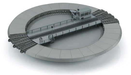
C-Gleis Drehscheibe
        74861
1 2 Bilder zum Aufbau und Anschluss
H ≥ 38 mm

    2
        Ø ≥ 288 mm

    3
                                     6x

                           ≤ 16 mm
3
4a 5
E334862
4b 6
4S88 AC
T T
1 2 3 4 5 6 7 8 9 10 11 12 13 14 15 16
7 9
22 23 24
25
21 26
20 27
19 28
18 29
17 30
16 1
15 2
14 3
13 4
12 5
8
11 6
10 9 8 7
5Bilder zum Aufbau und Anschluss 2 Illustrations pour montage et raccordement 2
Sicherheitshinweise 8 Consignes de sécurité 16
D F
Allgemeine Hinweise 8 Indications générales 16
Funktionen 8 Fonctions 16
Ergänzungen 8 Compléments 16
Anschluss 8 Raccordement 16
Aufbau 8 Montage 16
Wartung 9 Entretien 17
Betrieb 9 Exploitation 17
Gleispläne 42 Tracés des voies 42
Images for Setup and Connections 2 Afbeeldingen over opbouw en aansluiting 2
Safety Notes 12 Veiligheidswenken 20
General Notes 12 Algemene informatie 20
GB NL
Functions 12 Functies 20
Add-Ons 12 Uitbreidingen 20
Connections 12 Aansluiting 20
Setup 12 Opbouw 20
Maintenance 13 Onderhoud 21
Operation 13 Bedrijf 21
Track Plans 42 Spoorschema’s 42
6Imágenes para el montaje y la conexión 2 Bilder på montering och anslutning 2
Consejos de seguridad 24 Säkerhetsanvisningar 32
S
Indicaciones generales 24 Allmänna anvisningar 32
Funciones 24 Funktioner 32
Complementos 24 Utbyggnad 32
Conexión 24 Anslutning 32
Montaje 24 Montering 33
Mantenimiento 25 Underhåll 33
Empleo 25 Drift 33
Esquemas de vías 42 Spårplaner 42
Figure per il montaggio e il collegamento 2 Illustrationer til montering og tilslutning 2
Avvertenze di sicurezza 28 Sikkerhedsvejledning 36
Avvertenze generali 28 Generel vejledning 36
Funzioni
Ampliamenti
Collegamento
Montaggio
Manutenzione
Esercizio
Tracciati di binario
28
28
28
28
29
29
42
Montering
DK
Funktioner
Tilføjelser
Tilslutning
Vedligeholdelse
Drift
Sporplaner
36
36
36
36
37
37
42
7Sicherheitshinweise können auch mit dem Endstück 24001 zu einem vorbildge-
• nur zur Verwendung in geschlossenen Räumen rechten Blindgleis ausgebildet werden.
• ACHTUNG! Funktionsbedingte scharfe Kanten und Spitzen. Der Ringlokschuppen 72886 kann passend neben der Dreh-
• Verbaute LED`s entsprechen der Laserklasse 1 nach scheibe aufgestellt werden.
Norm EN 60825-1. Die Gleisanschlüsse sind für Märklin C-Gleise vorgese-
hen. Bei Anlagen mit Metall-Gleisen kann als Zufahrt das
Allgemeine Hinweise Übergangsgleis 24951 verwendet werden, bei Anlagen mit
• Die Bedienungsanleitung ist Bestandteil des Produktes K-Gleis das Übergangsgleis 24922.
und muss deshalb aufbewahrt sowie bei Weitergabe des
Produktes mitgegeben werden. Anschluss
• Entsorgung: www.maerklin.com/en/imprint.html Die Drehscheibe hat einen Anschluss zur Steuerung der
Drehscheibe mit einem digitalen Steuergerät (z.B. Central
Funktionen Station 2 / 3) sowie einen Gleisanschluss zur Versorgung
Die Drehscheibe 74861 ist sowohl bei analogem als auch bei des Gleises auf der Drehbühne (S. 2, Bild 1). Die beiden
digitalem Fahrbetrieb einsetzbar. Für den digitalen Betrieb Schienenprofile haben getrennte Anschlüsse so dass auch
der Drehscheibe selbst ist ein zusätzliches digitales Steu- ein Rückmeldedecoder angeschlossen werden kann (S. 5,
ergerät (mfx, MM oder DCC) notwendig. Ein eigener Span- Bild 9). Wird dies nicht gewünscht empfehlen wir die beiden
nungsanschluss für die Drehscheibe wird nicht benötigt. Schienenanschlüsse wie im Bild 1 gezeigt zu verbinden.
Der analoge Betrieb der Drehscheibe (nur mit 72760) ist Die Anschlussgleise der Drehscheibe werden nur durch
allerdings nur eingeschränkt möglich. die Gleise auf der Anlage versorgt. Die Versorgung der
Im Auslieferzustand sind 2 x 3 Anschlussgleise vorgesehen. Anschlussgleise über die Drehbühne ist nicht möglich.
Mit dem Erweiterungsset 74871 kann die Drehscheibe auf Aufbau
max. 30 Anschlussgleise (12°-Raster) ausgebaut werden.
Die Drehscheibe ist zum versenkten Einbau in der Anlage
Ergänzungen vorgesehen. Dazu ist in der Grundplatte eine kreisförmige
Die Rand-Segmente der Drehscheibe können beliebig aus- Aussparung mit einem Durchmesser von mindestens
getauscht werden und lassen somit eine optimale Anpas- 288 mm und einer für den Betrieb notwendigen Mindest-
sung an die gewünschte Gleisanlage zu (Randsegment nach höhe von 38 mm erforderlich (Seite 3, Bild 2). Es liegen 6
oben aus der Drehscheibe herausheben, Seite 4, Bilder 4). Kunststoffwinkel bei, die am Rand der Öffnung befestigt
werden (Seite 3, Bild 3). Die Drehscheibe wird dann auf
Mit der Erweiterung 74871 kann die Drehscheibe um weitere
diesen Winkeln aufgelegt. Die Winkel müssen so platziert
Anschlussgleise ergänzt werden. Diese Anschlussgleise
8werden, dass sie jeweils mittig unter einem Blind- oder Betrieb
Auffahrtsgleis angeordnet sind. Die Drehscheibe 74861 ist mit einem Multiprotokoll-Decoder
Beachten Sie bitte, dass die eingebaute Drehscheibe von ausgestattet. Ab Werk ist der Decoder auf den Betrieb mit
unten zugänglich sein sollte. MM/mfx eingestellt. In der Konfiguration (z.B. mit der Cen-
tral Station 3) kann der Decoder auf DCC-Betrieb umgestellt
1. Geeignete Stelle für die Drehscheibe auf der Anlage werden. Hier kann auch die Adresse angepasst werden.
auswählen (genug Platz auch nach unten; die Dreh- Voreingestellt sind die Adressen 225 für MM ( =^ keyboard 15)
scheibe sollte von unten zugänglich sein). und 225 für DCC.
2. Die Aussparung in der Anlagenplatte fräsen Die Drehscheibe kann mit maximal 2 x 15 Anschlussglei-
(∅ ≥ 288 mm). Die beiliegende Schablone kann bei der sen ausgestattet werden. Ausgehend vom Gleis 1 sind die
genauen Positionierung hilfreich sein. möglichen Anschlussgleise im Uhrzeigersinn durchnumme-
3. Die benötigten Anschlussgleise an der Drehscheibe riert (Seite 5, Bild 8). Nachdem zunächst die Drehrichtung
anbauen und die entsprechenden Abfragezapfen vorgegeben wurde, können die einzelnen Gleise wahlweise
überprüfen (siehe auch Bilder 5 & 6). direkt oder schrittweise angesprungen werden.
4. Drehscheibe in die Aussparung legen. Jetzt können die Eingaben werden von der Drehscheibe über unterschied-
geeigneten Stellen für die Befestigungswinkel auf der liche Beep-Töne quitiert.
Platte markiert werden. normale Eingabe Beep
5. Drehscheibe wieder auf die Seite legen und die Befe- Programmierung erfolgreich Beep Beep Beep
stigungswinkel am Rand der Aussparung anschrauben Fehler Beep Beep Beep
(Schrauben vorbohren).
Betrieb mit der Central Station 3
6. Drehscheibe elektrisch anschließen.
7. Drehscheibe einbauen und mit den vorgesehenen Die Drehscheibe 74861 muss wie andere mfx-fähige
Gleisen verbinden. Zubehörartikel über die Funktion „mfx-Artikel suchen“ ange-
meldet werden. Danach muss das Gleis 1 festgelegt und die
Die Drehscheibe muss schwimmend, zwangfrei und eben Drehscheibe initialisiert werden.
montiert sein!
Betrieb mit der Central Station 2
Wartung Die Drehscheibe wird zunächst über die Funktion „mfx-
Die Drehscheibe 74861 ist wartungsfrei. Artikel suchen“ im keyboard angemeldet (keyboard, Konfi-
guration, Taste . Danach kann sofort das Gleis 1 festgelegt
und die Drehscheibe initialisiert werden.
9Betrieb mit der Control Unit 6021 und Keyboard 6040 Gleis 1 selbst festlegen (nicht mit 72760)
Die Drehscheibe ist auf die Adresse 225 programmiert. 1. gewünschtes Gleis 1 anfahren
Nach dem Anschluss kann sofort damit begonnen werden 2. Anlage ausschalten („STOP“ am Steuergerät)
das Gleis 1 festzulegen und die Drehscheibe zu initialisieren. 3. Anlage wieder einschalten und innerhalb von 5 Sekunden
Betrieb mit dem Signal-Schaltpult 72760 (Analogbetrieb) die Tasten drücken
Alternativ zu einer Digital-Zentrale wie der Central Station Hinweis: Solange die Verriegelung der Bühne offen ist,
kann die Drehscheibe auch mit dem Stellpult 72760 gesteu- nimmt die Drehscheibe keine Schaltbefehle entgegen.
ert werden. Die Möglichkeiten sind jedoch sehr einge- Initialisierung (nicht mit 72760)
schränkt. Die Festlegung von Gleis 1, die Initialisierung und Bei der Initialisierung läuft die Drehscheibe ein Mal durch
das Anspringen von bestimmten Gleisen sind nicht möglich. den ganzen Kreis und liest die Anschlussgleise aus. So
Zum Anschluss der Drehscheibe an das Stellpult kann das bleibt die Drehscheibe im Betrieb nur noch an tatsächlichen
Kabel E242325 verwendet werden. Es muss jedoch der klei- Anschlussgleisen stehen.
nere Stecker (Signalseite!) dazu abgeschnitten werden. Für Wenn die Anordnung der Anschluss- oder Blindgleise an
den Betrieb mit dem Stellpult 72760 muss die Drehscheibe der Drehscheibe geändert wurden, muss die Drehscheibe
auf die Adresse 1 programmiert werden. neu initialisiert werden.
Drehscheibe mit 72760 auf Adresse 1 programmieren Die Initialisierung kann innerhalb von 5 Sekunden nach dem
Die hier beschriebene Programmierung funktioniert Einschalten über die Tasten gestartet
immer, egal welche Adresse zu Beginn eingestellt ist. Die werden.
Programmierung beginnt etwa eine Sekunde nach dem die Betrieb unter DCC
Spannung eingeschaltet wird. Die Drehscheibe 74861 ist auf den Betrieb unter MM / mfx
Taste 1 einschalten Taste 1 ausschalten voreingestellt. Sie kann auf DCC umprogrammiert werden.
Taste 2 einschalten Taste 2 ausschalten Das ist aber nur mit der Central Station 2 / 3 unter mfx mög-
Taste 3 einschalten Taste 3 ausschalten lich. Sie kann auch nur so wieder zurück gestellt werden.
Taste 4 einschalten Taste 4 ausschalten Das Umprogrammieren für den Betrieb mit dem Schaltpult
Mit dem Umgekehrten Ablauf (Taste 4 an, Taste 4 aus, ...) 72760 ist unter DCC nicht möglich.
kann die Drehscheibe wieder auf die Adresse 225 zurück
gestellt werden.
10CS2/CS3 6021 (/CS2) 72760 MS2
Adresse Funktion
end 225 Drehbewegung wird am nächsten Gleis beendet
input Taste 1 225 Ent- / Verriegeln der Bühne (ein = entriegeln)
clear 226 Weiterfahren nach STOP
turn Taste 2 226 Drehung um 180°
step Taste 4 227 Bühne dreht bis zum nächsten Gleis im Uhrzeigersinn
step Taste 3 227 Bühne dreht bis zum nächsten Gleis gegen den Uhrzeigersinn
228 Vorwahl der Drehrichtung im Uhrzeigersinn
228 Vorwahl der Drehrichtung gegen den Uhrzeigersinn
* 229 – 236 Zielgleis das angefahren werden soll
16
236 Geräusch: Ansage Drehscheibenwärter
17
237 Betriebsgeräusch aus
18
237 Betriebsgeräusch an
1
19
238 Soundsignal: „(Lok) rankommen“
2
20
238 Soundsignal: „(Bühne) wegfahren“
21 239 Licht aus (innen)
22
239 Licht an (innen)
23 240 Licht aus (außen)
24
240 Licht an (außen)
* In der CS3 können die Gleise über die Berührung des gewünschten Gleises auf dem Display angefahren werden. Es sind keine
besonderen Tasten vorgesehen.
Hinweis: Solange die Verriegelung der Bühne offen ist, nimmt die Drehscheibe keine Schaltbefehle entgegen.
11Safety Notes the 74871 extension set. These spoke tracks can also be
• Only for use in enclosed spaces finished off with the 24001 end piece to make a prototypical
• IMPORTANT! Sharp edges and points due to the model‘s blind track.
function. The 72886 roundhouse locomotive shed can be set up
• Built-in LEDs correspond to Laser Class 1 according to appropriately next to the turntable.
Norm EN 60825-1. The spoke tracks are designed for Märklin C Track. On
layouts with metal track, the 24951 adapter track can be
General Notes used as an approach. On layouts with K Track, use the 24922
• The operating instructions are a standard part of the adapter track.
product must therefore be kept in a safe place when
transferring the product to a third party. Connections
• Disposal: www.maerklin.com/en/imprint.html The turntable has a connection for control of the turntable
with a digital controller (example: Central Station 2 / 3) as
Functions well as a track connection for supplying power to the track
The 74861 turntable can be used with analog as well as on the turntable deck (page 2, figure 1). The two rails on
with digital running operation of locomotives. An additional the deck have separate connections so that a feedback
digital control device is necessary for operation of the decoder can also be connected (page 5, figure 9). It this is
turntable itself (mfx, MM, or DCC). The turntable does not not desired, we recommend connecting the two rail connec-
require its own voltage connection. Analog operation of tions as shown in figure 1.
the turntable (only with 72760) is however only possible in a The spoke tracks for the turntable can only be supplied with
limited manner. power from the tracks on the layout. It is not possible to
As delivered, the turntable is provided with 2 x 3 spoke supply power from the turntable deck.
tracks. The turntable can be expanded to a maximum of 30 Setup
spoke tracks (12° spacing) with the 74871 extension set.
The turntable is designed for sunken installation on the lay-
Add-Ons out. To do this, a circular opening in the benchwork with a
The edge segments for the turntable can be removed as diameter of at least 288 mm / 11-3/8“ and a minimum depth
desired and therefore allow optimal adaption to the desired of 38 mm / 1-1/2“ necessary for operation is required (page
track location (Lift the edge segments up and out of the 3, figure 2). Six (6) plastic brackets are included with the
turntable, page 4, figure 4). turntable, and they are mounted on the edge of the opening
The turntable can be expanded by several spoke tracks with (page 3, figure 3). The turntable is then installed on these
12brackets. The brackets must be placed so that they are Operation
centrally located under a blind or spoke track. The 74861 turntable 74861 is equipped with a multiprotocol
Please note that the installed turntable should be accessible decoder. As delivered from the factory, the decoder is set
from below. for operation with MM/mfx. The decoder can be changed
1. Select a suitable location for the turntable on the layout to DCC operation in the Configuration (ex. with the Central
(also enough space below; the turntable should be Station 3). The address can also be adjusted here.
accessible from below). The addresses 225 for MM (= ^ keyboard 15) and 225 for DCC
2. Cut the opening in the layout‘s benchwork (dia. ≥ 288 are preset.
mm / 11-3/8“). The pattern included with the turntable The turntable can be equipped with a maximum of 2 x 15
will help in positioning the turntable exactly. spoke tracks. Starting with Track 1, the possible spoke
3. Install the required spoke tracks on the turntable and tracks are consecutively clockwise (page 5, figure 8). After
check the appropriate detection pins (see also figures 5 first setting the direction of rotation, you can move the deck
& 6). directly to the individual tracks or in steps.
4. Lay the turntable in the opening. Now suitable locations Entries are confirmed by the turntable using various beeping
for the mounting brackets can be marked on the sounds.
benchwork. Normal entry Beep
5. Put the turntable aside and screw the mounting bra- Programming successful Beep Beep Beep
ckets on the edge of the opening (predrill screws). Errors Beep Beep Beep
6. Make the electrical connections for the turntable.
Operation with the Central Station 3
7. Install the turntable and connect it to the tracks provi-
ded for it. The 74861 turntable must like other mfx-capable accessory
The turntable must be mounted floating, free of constraints items be registered using the function „Search mfx Items“.
and level! After that, Track 1 must be defined and the turntable must
be initialized.
Maintenance Operation with the Central Station 2
The 74861 turntable requires no maintenance. The turntable is initially registered in the keyboard using
the function „Search mfx Items“ (keyboard, Configuration,
button . After that, Track 1 can be defined immediately and
the turntable can be initialized.
13Operation with the 6021 Control Unit and 6040 Keyboard Define Track 1 itself (not with 72760)
The turntable is programmed for address 225. 1. Run onto desired Track 1
After connections have been made, you can immediately 2. Turn off layout („STOP“ on controller)
begin to define Track 1 and then initialize the turntable. 3. Turn layout back on and within 5 seconds press the
Operation with the 72760 Signal Controller (Analog Ope- buttons
ration) Note: The turntable accepts no switching commands as
As an alternative to a digital central unit such as the Central long as the locking feature for the deck is open.
Station, the turntable can also be controlled with the 72760 Initializing (not with 72760)
controller. The options here are however very limited. De- When initializing, the turntable rotates a complete circle and
fining Track 1, the initialization and jumping from particular evaluates the spoke tracks. The turntable thus remains only
tracks are not possible. at actual spoke tracks.
The E242325 cable can be used to connect the turntable to If you change the order of the spoke or blind tracks on the
the controller. However, the smaller plug (signal side!) to turntable, the turntable must be initialized again.
it must be cut off. The turntable (ex. with a Central Station) The initialization can be started within 5 seconds using the
must be programmed to Address 1 for operation with the buttons after turning the layout on.
72760 controller (Reprograming with the controller is not
possible!). Operation with DCC
The 74861 turntable is preset for operation using MM /
Programming the Turntable with the 72760 for Address 1
mfx. It can be reprogrammed to DCC. This is only possible
The programming described here always works regardless however with the Central Station 2 / 3 using mfx. It can also
of which address is set at the beginning. The programming be reprogrammed back. Reprogramming for operation with
begins about one second after the voltage is turned on. the 72760 control box using DCC is not possible.
Turn Button 1 on turn Button 1 off
Turn Button 2 on turn Button 2 off
Turn Button 3 on turn Button 3 off
Turn Button 4 on turn Button 4 off
With the opposite procedure (Button 4 on, Button 4 off, ...),
the turntable can be set back to address 225.
14CS2/CS3 6021 (/CS2) 72760 MS2
address Function
end 225 Rotation is ended at the next track
input Button 1 225 Unlocking/Locking the turntable deck (on = unlock)
clear 226 Continuing to run after STOP
turn Button 2 226 Rotating 180°
step Button 4 227 Deck rotates clockwise to the next track
step Button 3 227 Deck rotates counterclockwise to the next track
228 Preselection of the rotation direction clockwise
228 Preselection of the rotation direction counterclockwise
* 229 – 236 Destination track to be stopped at
16
236 Sound: Announcement of the turntable operator
17
237 Operating sounds off
18
237 Operating sounds on
1
19
238 Sound signal: „(Locomotive) approaching“
2
20
238 Sound signal: „(Deck) turning away“
21 239 Light off (inside)
22
239 Light on (inside)
23 240 Light off (outside)
24
240 Light on (outside)
* In the CS 3, you can stop at the tracks by touching the desired track on the display. No special buttons are provided for this.
Note: The turntable accepts no switching commands as long as the locking feature for the deck is open.
15Consignes de sécurité être complétée par d’autres voies de raccordement. Avec
• Uniquement pour l’utilisation dans des pièces fermées l‘élément terminal réf. 24001, ces voies de raccordement
• ATTENTION! Arêtes coupantes. peuvent également former une voie sans issue réaliste.
• Les LED intégrées correspondent à la classe de laser 1 La rotonde réf. 72886 peut tout à fait trouver sa place à côté
selon la norme EN 60825-1. de la plaque tournante.
Les raccordements de voie sont prévus pour la voie C
Indications générales Märklin. Pour des réseaux avec éléments de voie métal-
• La notice d‘utilisation fait partie intégrante du produit ; lique, l‘accès peut être assuré par l’élément de transition
elle doit donc être conservée et, le cas échéant, transmi- réf. 24951 et pour les réseau avec voie K par l‘élément de
se avec le produit. transition réf. 24922.
• Élimination www.maerklin.com/en/imprint.html Raccordement
Fonctions La plaque tournante présente une connexion pour un appareil
La plaque tournante réf. 74861 peut être utilisée aussi bien en de commande numérique (tel que Central Station 2 / 3) ainsi
mode d’exploitation analogique qu’en mode d’exploitation qu’une connexion pour l’’alimentation de la voie sur le pont
numérique. L’exploitation de la plaque tournante elle-même tournant (P. 2, image 1). Les deux profilés de rail possèdent
nécessite un appareil de commande numérique (mfx, MM des connexions distinctes, ce qui permet également de
ou DCC) supplémentaire. La plaque tournante n‘a pas besoin raccorder un décodeur de rétrosignalisation (P. 5, image 9). Si
d‘avoir sa propre alimentation. L’exploitation analogique de ce n’est pas votre souhait, nous vous conseillons de relier les
la plaque tournante (uniquement avec 72760) n’est toutefois deux connexions tel que montré sur l’image 1.
possible que de manière limitée. Les voies de raccordement de la plaque tournante sont alimen-
Le coffret comprend 2x3 voies de raccordement. Le coffret de tées uniquement par les voies du réseau. L’alimentation des
complément réf. 74871 permet d‘agrandir la plaque tournante voies de raccordement via le pont tournant n’est pas possible.
pour max. 30 voies de raccordement (selon schéma de 12°). Montage
Compléments La plaque tournante est prévue pour une installation dans le
Les segments de bordure de la plaque tournante peuvent être plateau du réseau. A cet effet, le plateau doit présenter une
échangés à votre guise et permettent ainsi une adaptation découpe circulaire d’au moins 288 mm de diamètre et d’une
optimale au schéma des voies souhaité (soulever le segment hauteur minimale (nécessaire pour l’exploitation) de 38 mm
pour le sortir de la plaque tournante, page 4, images 4). (page 3, image 2). Sont fournies six équerres en plastique à
Grâce à l’extension réf. 74871, la plaque tournante peut fixer sur le bord de l’ouverture (page 3, image 3). La plaque
16tournante est alors posée sur ces équerres. Les équerres multiprotocole. Au départ d’usine, le décodeur est paramét-
doivent être positionnées de sorte à être respectivement ré pour une exploitation avec MM/mfx. Dans la configurati-
centrées sous une voie sans issue ou une voie d‘accès. on (par ex. avec la Central Station 3), le décodeur peut être
Veillez à ce que la plaque tournante montée soit accessible paramétré pour une exploitation DCC. L’adresse peut alors
par en dessous. également être adaptée.
1. Choisir le bon endroit pour l’implantation de la plaque Prédéfinies sont les adresses 225 pour MM (= ^ keyboard 15)
tournante sur le réseau (veillez à avoir suffisamment de et 225 pour DCC.
d’espace également vers le bas, la plaque tournante La plaque tournante peut être équipée au maximum de 2 x
doit être accessible par en dessous). 15 voies de raccordement. En partant de la voie 1, les voies
2. Percer le trou dans le plateau du réseau (∅ ≥ 288 mm). de raccordement possibles sont numérotées dans le sens
Le gabarit fourni peut faciliter le bon positionnement de des aiguilles d‘une montre (page 5, image 8). Une fois que le
la plaque. sens de rotation a été défini, les différentes voies peuvent
3. Brancher les voies de raccordement nécessaires à la être abordées au choix directement ou pas à pas.
plaque tournante et vérifier les plots de contrôle (voir Les entrées sont confirmées par la plaque tournantes via
également images 5 & 6). différents « bip sonores ».
4. Positionner la plaque tournante dans l’orifice. Le Entrée normale Beep
positionnement adéquat des équerres de fixation peut Programmation réussie Beep Beep Beep
maintenant être marqué sur le plateau du réseau. Erreur Beep Beep Beep
5. Retirer la plaque tournante et visser les équerres de Exploitation avec la Central Station 3
fixation sur le bord de l’orifice (vis de pré-perçage).
Tout comme d‘autres accessoires compatibles mfx, la pla-
6. Effectuer le raccordement électrique de la plaque.
que tournante réf. 74861 doit être enregistrée via la fonction
7. Insérer la plaque tournante et la relier aux voies pré- « Rechercher articles mfx ». La voie 1 doit ensuite être
vues. déterminée et la plaque tournante initialisée.
La platine doit être montée flottante, sans contraintes et de
niveau ! Exploitation avec la Central Station 2
La plaque tournante est d‘abord enregistrée dans le key-
Entretien board via la fonction « Rechercher articles mfx » (keyboard,
La plaque tournante réf. 74861 ne nécessite aucun entretien. configuration, touche . La voie 1 peut ensuite immédiate-
ment être déterminée et la plaque tournante initialisée.
Exploitation
La plaque tournante réf. 74861 est équipée d’un décodeur
17Exploitation avec la Control Unit 6021 et le Keyboard 6040 Déterminez vous-même la voie 1
La plaque tournante est programmée sur l’adresse 225. (et non avec le pupitre réf. 72760)
Une fois la connexion établie, vous pouvez immédiatement 1. Entrer sur la voie 1 choisie
déterminer la voie 1 et initialiser la plaque tournante. 2. Mettre le réseau hors tension (« STOP » sur l‘appareil de
Exploitation avec le pupitre de commande pour signaux commande)
72760 (exploitation analogique) 3. Remettre le réseau sous tension et en l’espace de 5 se-
A la place d‘une centrale numérique telle que la Central Stati- condes, appuyer sur les touches
on, la plaque tournante peut également être commandée avec Remarque : Tant que le verrouillage du pont est ouvert, la
le pupitre de commande réf. 72760. Les possibilités sont toute- plaque tournante n’exécute aucun ordre de commande.
fois très limitées. La détermination de la voie 1, l’initialisation Initialisation (pas avec 72760)
et l‘accès à certaines voies ne sont pas possibles. Lors de l‘initialisation, la plaque tournante fait une fois le
Le raccordement de la plaque tournante au pupitre de tour complet et sélectionne les voies de raccordement. Ain-
commande peut se faire via le câble E242325. A cet effet, si, la plaque tournante ne s’arrête ensuite plus que devant
le connecteur le plus petit (côté signal!), doit toutefois être les voies de raccordement effectives.
supprimé. Pour l’exploitation avec le pupitre de commande La modification de l’ordre des voies de raccordement ou
réf. 72760, la plaque tournante doit être programmée voies sans issue sur la plaque tournante nécessite sa
(par ex. avec une Central Station) sur l’adresse 1 (le chan- réinitialisation.
gement de programmation n’est pas possible avec le pupitre L‘initialisation peut être lancée dans les 5 secondes suivant
de commande!). la mise sous tension via les touches .
Programmer la plaque tournante avec 72760 sur l’adresse 1 Exploitation sous DCC
La programmation décrite ici fonctionne toujours, quelle que La plaque tournante réf. 74861 est préprogrammée pour
soit l‘adresse définie au départ. La programmation débute l’exploitation sous MM / mfx. Elle peut être reprogrammée
environ une seconde après la mise sous tension. pour l’exploitation sous DCC. Toutefois, cela est possible
Enclencher touche 1 Désenclencher touche 1 uniquement avec la Central Station 2 /3 sous mfx. Ce n’est
Enclencher touche 2 Désenclencher touche 2 qu’à cette condition également qu’elle pourra être réinitiali-
Enclencher touche 3 Désenclencher touche 3 sée. La reprogrammation pour l’exploitation avec le pupitre
Enclencher touche 4 Désenclencher touche 4 de commande réf. 72760 n’est pas possible sous DCC.
Avec le déroulement inverse (enclencher touche 4, désen-
clencher touche 4, la plaque tournante peut être réinitialisée
à l’adresse 225.
18CS2/CS3 6021 (/CS2) 72760 MS2
adresse Fonction
end 225 La rotation s’arrête à la prochaine voie
input Touche 1 225 Déverrouillage/Verrouillage de la plate-forme (marche = ouvrir)
clear 226 Reprise après STOP
turn Touche 2 226 Rotation de 180°
step Touche 4 227 La plate-forme tourne dans le sens des aiguilles d’une montre jusqu’à la prochaine voie.
La plate-forme tourne dans le sens inverse des aiguilles d’une montre jusqu’à la
step Touche 3 227
prochaine voie.
228 Présélection du sens de rotation dans le sens des aiguilles d'une montre
228 Présélection du sens de rotation dans le sens inverse des aiguilles d'une montre
* 229 – 236 Voie cible devant être empruntée
16
236 Bruitage Annonce Agent plaque tournante
17
237 Bruitage d’exploitation désactivé
18
237 Bruitage d’exploitation activé
1
19
238 Signal sonore : « approcher (la locomotive) »
2
20
238 Signal sonore : « « Éloigner (le pont) »
21 239 Éclairage désactivé (intérieur)
22
239 Éclairage activé (intérieur)
23 240 Éclairage désactivé (extérieur)
24
240 Éclairage activé (extérieur)
* Avec la CS3, les voies peuvent être sélectionnées par simple effleurement de l’écran. Il n’y pas de touches particulières prévues à
cet effet.
Remarque : Tant que le verrouillage du pont est ouvert, la plaque tournante n’exécute aucun ordre de commande. 19Veiligheidswenken Ringlocomotiefloods 72886 past naast de draaischijf.
• alleen voor gebruik in gesloten ruimtes De spooraansluitingen zijn voorzien voor Märklin C-spoor.
• LET OP! Deze component heeft scherpe randen en punten. Bij modelbanen met metalen rails kan overgangsspoor 24951
• Ingebouwde leds zijn laserklasse 1 volgens de norm worden gebruikt, bij modelbanen met K-spoor overgangs-
EN 60825-1. spoor 24922.
Algemene informatie Aansluiting
• De handleiding maakt deel uit van het product en moet De draaischijf heeft een aansluiting voor een digitale
daarom worden bewaard en meegegeven als het product regelaar van de draaischijf (bv. Central Station 2/3 en een
aan een ander persoon wordt doorgegeven. spooraansluiting voor voeding van het spoor op de draai-
brug (pag. 2 afb. 1). De beide railsrofielen hebben aparte
• Afvalverwijdering: www.maerklin.com/en/imprint.html
aansluitingen, zodat er ook een feedbackdecoder kan
Functies worden aangesloten (pag. 5, afb. 9). Als dit niet het geval
De draaischijf 74861 kan worden ingezet bij analoog en is, bevelen wij aan de beide railsaansluitingen te verbinden
digitaal rijbedrijf. Voor de draaischijf zelf is een digitale zoals op afb. 1 te zien is.
regelaar (mfx, MM of DCC) nodig. De draaischijf heeft geen De aansluitsporen van de draaischijf worden alleen gevoed
eigen spanningaansluiting nodig. Analoog bedrijf van de via de sporen op de spoorlijn. Voeding van de aansluitspo-
draaischijf (alleen met 72760) is echter slechts beperkt ren via de draaibrug is niet mogelijk.
mogelijk. Opbouw
Bij levering zijn 2 x 3 aansluitsporen voorzien. Met uitbrei-
De draaischijf wordt verlaagd in de modelbaan ingebouwd.
dingsset 74871 kan de draaischijf worden uitgebreid tot max.
Hiervoor is in de grondplaat een cirkelvormige uitsparing
30 aansluitsporen (12°-raster).
nodig met een diameter van minstens 288 mm en een
Uitbreidingen minimumhoogte van 38 mm (pag. 3, afb. 2). Bij levering inbe-
De randsegmenten van de draaischijf kunnen worden ver- grepen zijn 6 kunststof hoekprofielen die aan de rand van de
vangen en zo optimaal worden aangepast aan de modelba- uitsparing worden bevestigd (pag. 3, afb. 3). De draaischijf
an (randsegment naar boven uit de draaischijf halen, pag. 4, wordt dan op deze hoekprofielen gelegd. De hoekprofielen
afb. 4a en 4b). moet zo worden geplaatst dat ze altijd in het midden onder
een kop- of aankomstspoor liggen.
Met uitbreidingsset 74871 kan de draaischijf worden aange-
vuld met verdere aansluitsporen. Deze aansluitsporen kun- Let op: de draaischijf moet van onderen toegankelijk zijn.
nen met sluitstuk 24001 ook een getrouw kopspoor vormen.
201. Kies op de modelbaan een geschikte plek voor de Bedrijf
draaischijf. Let op dat er genoeg ruimte onder zit. De Draaischijf 74861 heeft een multiprotocol-decoder. De
draaischijf moet van onderen toegankelijk zijn. decoder staat standaard ingesteld op Bedrijf MM/mfx. In de
2. Zaag de uitsparing (∅ ≥ 288 mm).in de modelbaan- configuratie (bv. met de Central Station 3) kan de decoder
plaat. De bijgevoegde sjabloon is handig om precies te op DCC-bedrijf worden omgesteld. Hier kan ook het adres
kunnen werken. worden aangepast.
3. Breng de aansluitsporen aan op de draaischijf en De adressen 225 voor MM (= ^ keyboard 15) en 225 voor DCC
controleer de uitleesprofielen (zie ook afb. 5 & 6). staan al ingesteld..
4. Plaats de draaischijf in de uitsparing. Nu kunnen de De draaischijf kan maximaal 2 x 15 aansluitsporen hebben.
posities voor de bevestigingsprofielen op de plaat Beginnend met spoor 1 zijn de aansluitsporen met de klok
gemarkeerd worden. mee genummerd (pag. 5, afb. 8). Nadat de draairichting is
5. Leg de draaischijf weer weg en schroef de bevesti- aangegeven, kunnen de sporen naar keuze direct of staps-
gingsprofielen aan de rand van de uitsparing (schroe- gewijs worden aangesprongen.
ven voorboren). Invoeren van instellingen wordt door de draaischijf beve-
6. Sluit de draaischijf elektrisch aan. stigd met verschillende pieptonen.
7. Monteer de draaischijf en sluit de sporen aan. normale invoer Beep
De draaitafel moet zwevend, vrij van beperkingen en Programmering succesvol Beep Beep Beep
waterpas worden gemonteerd! Fout Beep Beep Beep
Onderhoud Bedrijf met Central Station 3
De draaischijf 74861 is onderhoudsvrij. Draaischijf 74861 moet net als andere accessoires die met
mfx werken via de functie “mfx-Artikel suchen“ worden
aangemeld. Daarna moet spoor 1 worden vastgelegd en de
draaischijf worden geïnitialiseerd.
Bedrijf met Central Station 2
De draaischijf wordt eerst aangemeld via de de functie
“mfx-Artikel suchen“ in het keyboard (keyboard, configura-
tie, toets ). Daarna kan spoor 1 meteen worden vastgelegd
en de draaischijf worden geïnitialiseerd.
21Bedrijf met Control Unit 6021 en Keyboard 6040 Spoor 1 zelf vastleggen (niet met 72760).
De draaischijf is geprogrammeerd op adres 225. 1. naar spoor 1 rijden
Na het aansluiten kan meteen worden begonnen met het va- 2. draaischijf uitschakelen (STOP op regelaar)
stleggen van spoor 1 en het initialiseren van de draaischijf. 3. draaischijf weer inschakelen en binnen 5 seconden de
Bedrijf met signaal-schakelbord 72760 (analoog bedrijf) toetsen indrukken
Als alternatief voor een digitale regeling als de Central Sta- Let op: zolang de vergrendeling van de brug open is, neemt
tion kan de draaischijf ook worden geregeld via schakelbord de draaischijf geen schakelcommando’s aan.
72760. De mogelijkheden zijn dan wel zeer beperkt. Zelf Initialiseren (niet met 72760)
vastleggen van spoor 1, initialiseren en aanspringen van Bij het initialiseren loopt de draaischijf een keer door de hele
bepaalde sporen zijn dan niet mogelijk. cirkel en leest de aansluitsporen uit. Op de manier blijft de
Voor aansluiting van de draaischijf op het schakelbord kan draaischijf in bedrijf alleen nog bij de aansluitsporen staan.
kabel E242325 worden gebruikt. De kleinere stekker (sein- Als u de rangschikking van aansluit- of kopsporen op de
kant!) moet dan wel worden afgesneden. Voor bedrijf met draaischijf verandert, moet de draaischijf opnieuw geïnitia-
schakelbord 72760 moet de draaischijf (bv. met een Central liseerd worden.
Station) op adres 1 worden geprogrammeerd. Omprogram- Het initialiseren kan binnen 5 seconden na het inschakelen
meren is met het schakelbord niet mogelijk. met de toetsen worden gestart.
Draaischijf met 72760 op adres 1 programmeren Bedrijf met DCC
De hier beschreven programmering werkt altijd, ongeacht Draaischijf 74861 is ingesteld op bedrijf met MM/mfx. Hij kan
welk adres in het begin is ingesteld. De programmering worden omgeprogrammeerd op DCC. Dat is echter alleen
begint ongeveer een seconde na het inschakelen van de mogelijk met Central Station 2/3 met mfx. Ook een reset
spanning is alleen zo mogelijk. Omprogrammeren voor bedrijf met
Toets 1 inschakelen toets 1 uitschakelen schakelbord 72760 is met DCC niet mogelijk.
Toets 2 inschakelen toets 2 uitschakelen
Toets 3 inschakelen toets 3 uitschakelen
Toets 4 inschakelen toets 4 uitschakelen
Met het omgekeerde proces (toets 4 aan, toets 4 uit, ...) kan
de draaischijf weer worden gereset op adres 225.
22CS2/CS3 6021 (/CS2) 72760 MS2 Functie
adres
end 225 Draaibeweging stopt bij het volgende spoor.
input Toets 1 225 Ont-/vergrendelen van de brug (aan = ontgrendelen)
clear 226 Doorrijden naar STOP
turn Toets 2 226 180° draaien
step Toets 4 227 Brug draait met de klok mee naar het volgende spoor.
step Toets 3 227 Brug draait tegen de klok in naar het volgende spoor.
228 Keuze van de draairichting met de klok mee
228 Keuze van de draairichting tegen de klok in
* 229 – 236 Doelspoor waar de loc naar toe moet rijden
16
236 Geluid: aankondiging draaischijfbewaker
17
237 Bedrijfsgeluid uit
18
237 Bedrijfsgeluid aan
1
19
238 Soundsignaal loc naderen
2
20
238 Soundsignaal (brug) wegrijden
21 239 Licht uit (binnen)
22
239 Licht aan (binnen)
23 240 Licht uit (buiten)
24
240 Licht aan (buiten)
* In CS3 kan er via aanraken van het gewenste spoor op het display naar de sporen worden gereden . Er zijn geen speciale toetsen
voorzien.
Let op: zolang de vergrendeling van de brug open is, neemt de draaischijf geen schakelcommando’s aan.
23Consejos de seguridad Con el set de ampliación 74871 es posible incorporar vías de
• Está previsto para su uso únicamente en recintos cerrados enlace adicionales al puente giratorio. Estas vías de enlace
• ¡ATENCIÓN! El equipo, debido a sus características se pueden convertir en una vía ciega, como en el modelo
funcionales, presenta cantos y puntas cortantes. real, también con la pieza terminal 24001.
• Los LEDs integrados corresponden a la clase láser 1 El depósito circular de locomotoras (cocherón) 72886 se
según la norma EN 60825-1. puede montar a juego con el puente giratorio, junto a éste.
Las conexiones a las vías se han previsto para vías C de
Indicaciones generales Märklin. En maquetas de trenes con vías metálicas se
• Las instrucciones de empleo forman parte integrante del puede emplear como acceso a las vías también la vía de
producto y, por este motivo, deben conservarse y entregar- transición 24951 y en maquetas de trenes con vía K la vía de
se al nuevo comprador en el caso de venta del producto. transición 24922.
• Para su eliminación: www.maerklin.com/en/imprint.html Conexión
Funciones El puente giratorio posee una conexión para control del pu-
El puente giratorio 74861 se puede utilizar en circulación tanto ente giratorio a una unidad de control digital (p. ej., Central
en modo analógico como en digital. Para el empleo del propio Station 2/3) así como una conexión de vía para la alimenta-
puente giratorio se requiere una unidad de control digital ción de la vía en el puente giratorio (pág. 2, imagen 1). Los
adicional (mfx, MM o DCC). No se requiere una conexión dos perfiles de carril poseen conexiones independientes
de tensión propia para el puente giratorio. Sin embargo, el de tal modo que se pueda conectar también un decoder de
funcionamiento analógico del puente transbordador (solo con señalización de respuesta (pág. 5, imagen 9). Si esto no se
72760) es posible solo con limitaciones. En el estado en que desea, recomendamos interconectar ambas conexiones de
se entrega se han previsto 2 grupos de 3 vías de enlace. El carril como se muestra en la imagen 1.
puente giratorio se puede ampliar a un máximo de 30 vías de Las vías de enlace del puente giratorio se alimentan únicamente
enlace (paso entre vías de 12°) con el set de ampliación 74871. desde las vías de la maqueta de trenes. No es posible la alimen-
tación de las vías de enlace a través de la plataforma giratoria.
Complementos
Los segmentos periféricos del puente giratorio se pueden Montaje
sustituir libremente y, por tanto, permiten una adaptación El puente giratorio se ha previsto para su montaje escamo-
óptima a la instalación de vías deseada (simplemente teado en la maqueta de trenes. Para tal fin, se requiere en la
extraer el segmento periférico hacia arriba apartándolo del placa base una abertura circular con un diámetro de como
puente giratorio, página 4, imágenes 4). mínimo 288 mm y una altura mínima de 38 mm para su fun-
24cionamiento (página 3, imagen 2). Se adjuntan 6 ángulos de Empleo
plástico que se sujetan en el borde de la abertura (página 3, El puente giratorio 74861 está equipado con un decoder
imagen 3). En tal caso, el puente giratorio se monta en estos multiprotocolo. De fábrica, el decoder está configurado a
ángulos. Los ángulos se deben colocar de tal modo que funcionamiento con MM/mfx. En la configuración (p. ej., con
estén situados cada uno centrado debajo de una vía ciega o la Central Station 3), el decoder se puede cambiar a funcio-
una vía de acceso. namiento en modo DCC. Aquí se puede adaptar también la
Tenga presente que el puente giratorio incorporado debe dirección. Están preconfiguradas las direcciones 225 para
estar accesible desde abajo. MM (= ^ keyboard 15) y 225 para DCC.
1. Elegir un punto adecuado para la plataforma giratoria en la El puente giratorio se puede equipar con un máximo de 2
maqueta de trenes (suficiente espacio también hacia aba- grupos de 15 vías de enlace. Partiendo de la vía 1 están nu-
jo, el puente giratorio debe estar accesible desde abajo). meradas secuencialmente en el sentido de las manecillas del
2. Fresar la abertura en la plancha de la maqueta de reloj las vías de enlace posibles (página 5, imagen 8). Después
trenes (∅ ≥ 288 mm). La plantilla que se adjunta puede de haber predefinido el sentido de giro es posible saltar a
resultar útil para lograr un posicionamiento exacto. través de las distintas vías bien directamente o paso a paso.
3. Montar las vías de enlace necesarias en el puente Los comandos introducidos son confirmados por el puente
giratorio y revisar los correspondientes pivotes de transbordador emitiendo diferentes pitidos.
confirmación (véanse también las imágenes 5 y 6). Entrada de comando normal Pitido
4. Colocar el puente giratorio en la abertura. Ahora se Programación correcta Pitido Pitido Pitido
pueden marcar en el tablero los puntos adecuados Error Pitido Pitido Pitido
para las escuadras de fijación.
5. Volver a colocar el puente giratorio en el lateral y ator- Funcionamiento con la Central Station 3
nillar las escuadras de fijación al borde de la abertura El puente giratorio 74861 debe darse de alta, al igual que
(tornillos pre-perforados). otros artículos accesorios aptos para mfx, mediante la fun-
6. Conectar eléctricamente el puente giratorio. ción „Buscar artículo mfx“. A continuación, se debe definir
7. Montar el puente giratorio e interconectarlo a las vías la vía 1 y se debe inicializar el puente transbordador.
previstas. Funcionamiento con la Central Station 2
La plataforma giratoria debe estar montada de forma En primer lugar, se debe dar de alta el puente giratorio
flotante, libre de obstáculos y nivelada. mediante la función „Buscar artículos mfx“ en el keyboard
(keyboard, Configuración, tecla . A continuación, se
Mantenimiento puede definir inmediatamente la vía 1 y se debe inicializar el
El puente giratorio 74861 está exento de mantenimiento. puente transbordador.
25Funcionamiento con la Control Unit 6021 y el keyboard 6040 4, ...), es posible resetear el puente transbordador a la
Este puente transbordador viene programado de fábrica a la dirección 225.
dirección 225. Definir la propia vía 1 (no con el 72760)
Tras la conexión se puede comenzar inmediatamente a 1. desplazamiento a la vía 1 deseada
definir la vía 1 y a inicializar el puente transbordador. 2. Desconectar la maqueta de trenes („STOP“ en la unidad
Funcionamiento con el pupitre de mando de señales 72760 de control)
(modo analógico) 3. Conectar de nuevo la maqueta de trenes y pul-
Como alternativa a una central digital como la Central Station sar antes de transcurridos 5 segundos las teclas
es posible controlar el puente giratorio también con el pupitre
de posicionamiento de agujas 72760. Sin embargo, las posibili- Nota: Mientras esté abierto el enclavamiento de la plata-
dades son muy limitadas. La especificación de vía 1, la iniciali- forma giratoria, el puente giratorio no admite comandos de
zación y el salto desde determinadas vías no son posibles. maniobra.
Para la conexión del puente giratorio al pupitre de posi- Inicialización (no con el 72760)
cionamiento de agujas se puede utilizar el cable E242325. En la inicialización, el puente giratorio recorre una vez todo
Sin embargo, para tal fin se debe seccionar el conector el círculo y lee las vías de enlace instaladas. De este modo,
más pequeño (¡lado de la seña!). Para el funcionamiento durante su funcionamiento, el puente giratorio se detiene
con el pupitre de posicionamiento de agujas 72760 se debe tan solo en las vías de enlace realmente existentes.
programar en la dirección 1 el puente giratorio (p. ej., con
una Central Station) (¡no es posible una reprogramación con Si se ha modificado la disposición de las vías de enlace o
el pupitre de posicionamiento de agujas!). vías ciegas en el puente giratorio, es preciso reinicializar el
puente giratorio.
Programar el puente transbordador con 72760 a la dirección 1 La inicialización puede realizarse en un margen de 5 se-
La programación aquí descrita funciona siempre, inde- gundos después de haber conectado el puente mediante las
pendientemente de qué dirección se haya configurado al teclas
comienzo. La programación comienza aproximadamente un Funcionamiento en DCC
segundo después de conectar la tensión.
Activar tecla 1 Desactivar tecla 1 El carro transbordador 74861 está preconfigurado para el funcio-
Activar tecla 2 Desactivar tecla 2 namiento en modo MM / mfx. Se puede reprogramar a funciona-
Activar tecla 3 Desactivar tecla 3 miento en DCC. Pero esto es posible únicamente con la Central
Activar tecla 4 Desactivar tecla 4 Station 2 / 3 en mfx. El carro transbordador se puede resetear de
nuevo solo de este modo. La reprogramación para el funciona-
Con la secuencia inversa (Activar tecla 4, Desactivar tecla miento con el pupitre de mando 72760 no es posible en DCC.
26CS2/CS3 6021 (/CS2) 72760 MS2
dirección Funktion
end 225 El movimiento de giro finaliza en la vía siguiente
input Tecla 1 225 Desenclavamiento/enclavamiento de la plataforma (encendida = desenclavamiento)
clear 226 Continuar después de STOP
turn Tecla 2 226 Giro en 180°
step Tecla 4 227 La plataforma gira hasta la siguiente vía en el sentido de las manecillas del reloj
step Tecla 3 227 La plataforma gira hasta la siguiente vía en sentido contrario al de las manecillas del reloj
228 Preselección de sentido de giro en el sentido de las manecillas del reloj
228 Preselección del sentido de giro en el sentido contrario al de las manecillas del reloj
* 229 – 236 Vía destino a la cual se desea efectuar el desplazamiento
16
236 Sonido: Locución para operario responsable del carro transbordador
17
237 Desactivar sonido de explotación
18
237 Activar sonido de explotación
1
19
238 Señal de sonido: ‚Acercar la (loco)‘
2
20
238 eñal de sonido: ‚Alejar la (plataforma giratoria)‘
21 239 Apagar luces (interiores)
22
239 Encender luces (interiores)
23 240 Apagar luces (exteriores)
24
240 Encender luces (exteriores)
* En la CS3 es posible efectuar el desplazamiento a las distintas vías tocando la vía deseada en cuestión en la pantalla. No se han
previsto teclas especiales.
Nota: Mientras esté abierto el enclavamiento de la plataforma giratoria, el puente giratorio no admite comandos de maniobra.
27Avvertenze di sicurezza (Rimozione verso l‘alto di un segmento di bordo dalla piatta-
• soltanto per un utilizzo in luoghi asciutti forma girevole, si veda pagina 4, figura 4).
• ATTENZIONE! Spigoli e punte acuminati per necessità Con l‘ampliamento 74871 la piattaforma può venire ampliata
funzionali. con degli ulteriori binari di connessione. Questi binari di con-
• I LED incorporati corrispondono alla classe di Laser 1 in nessione possono anche venire conformati con l‘elemento
base alla normativa EN 60825-1. terminale 24001 formando un binario cieco fedele al prototipo.
La rimessa locomotive a rotonda 72886 può venire adegua-
Avvertenze generali tamente collocata vicino alla piattaforma girevole.
• Tali istruzioni di azionamento costituiscono parte integrante Le connessioni di binario sono predisposte per i binari Mär-
del prodotto e devono pertanto venire conservate nonché con- klin C. In caso di impianti con binari di metallo M può venire
segnate accluse in caso di cessione ad altri di tale prodotto. impiegato quale accesso il binario di transizione 24951, in
• Smaltimento: www.maerklin.com/en/imprint.html caso di impianti con binari K il binario di transizione 24922.
Funzioni Collegamento
La piattaforma girevole 74861 è utilizzabile tanto in caso di La piattaforma girevole ha una sua connessione per il coman-
esercizio di marcia analogico, quanto anche in caso di eserci- do della piattaforma girevole con un apparato di comando
zio di marcia digitale. Per il funzionamento della piattaforma digitale (ad es. Central Station 2 / 3) nonché un collegamento
girevole stessa è necessario un apparato di comando digitale al binario per l‘alimentazione del binario sul ponte girevole
aggiuntivo (mfx, MM oppure DCC). Un proprio collegamento (pag. 2, figura 1). Entrambi i profilati di rotaia hanno dei col-
di tensione per la piattaforma girevole non viene richiesto. Il legamenti separati, cosicché può venire collegato anche un
funzionamento analogico della piattaforma girevole (solo con Decoder per avviso di ritorno (pag. 5, figura 9). Qualora questo
72760) è comunque possibile solo in modo limitato. non sia desiderato, noi consigliamo di collegare entrambe le
Nelle condizioni di fornitura sono previsti 2 x 3 binari di con- connessioni alle rotaie come mostrato nella figura 1.
nessione. Con il corredo di ampliamento 74871 la piattafor- I binari di connessione della piattaforma girevole vengono ali-
ma girevole può venire trasformata sino al max. a 30 binari mentati solo attraverso i binari sull‘impianto. L‘alimentazione dei
di connessione (griglia di 12°). binari di connessione attraverso il ponte girevole non è possibile.
Ampliamenti Montaggio
I segmenti di bordo della piattaforma girevole possono La piattaforma girevole è prevista per il montaggio incassato
venire scambiati tra loro a piacere e consentono pertanto nell‘impianto. A tale scopo nella plancia di base è neces-
un adattamento ottimale al desiderato impianto di binario saria una cavità di forma circolare con un diametro come
28minimo di 288 mm ed un‘altezza minima necessaria per il Esercizio
funzionamento di 38 mm (pagina 3, figura 2). Vi sono acclusi La piattaforma girevole 74861 è equipaggiata con un Deco-
6 angolari di materiale sintetico, i quali vengono fissati sul der multi-protocollo. Dalla fabbrica il Decoder è impostato
bordo dell‘apertura (pagina 3, figura 3). La piattaforma gire- sull‘esercizio con MM/mfx. Nella configurazione (ad es.
vole viene allora collocata sopra questi angolari. Gli angolari con la Central Station 3) il Decoder può venire convertito
devono venire piazzati cosicché essi siano disposti ciascuno all‘esercizio DCC. Qui può venire adattato anche l‘indirizzo.
centralmente sotto un binario cieco o di accesso. Preventivamente impostati sono gli indirizzi 225 per MM
Vogliate prestare attenzione al fatto che la piattaforma (=^ keyboard 15) e 225 per DCC.
girevole installata dovrà essere accessibile da sotto. La piattaforma girevole può venire equipaggiata con al
1. Selezionare sull‘impianto un punto adatto per la piattafor- massimo 2 x 15 binari di connessione. Incominciando dal
ma girevole (abbastanza spazio anche verso il basso; la binario 1, i possibili binari di connessione sono numerati
piattaforma girevole dovrà essere accessibile da sotto). sequenzialmente nel senso delle lancette dell‘orologio (pa-
2. Fresare la cavità nella plancia dell‘impianto (∅ ≥ 288 gina 5, figura 8). Dopo che inizialmente è stato specificato
mm). L‘acclusa dima può essere assai utile per l‘esatto il senso di rotazione, ai singoli binari si può a scelta saltare
posizionamento. direttamente oppure passo per passo.
3. Applicare alla piattaforma girevole i binari di connes- Gli inserimenti vengono riconosciuti dalla piattaforma
sione necessari e verificare le corrispondenti spine di girevole tramite differenti suoni di Bip.
riscontro (si vedano anche le figure 5 & 6). inserimento normale Bip
4. Alloggiare la piattaforma girevole nella cavità. Adesso Programmazione eseguita
possono venire marcati sulla plancia i punti adeguati Bip Bip Bip
con successo
per gli angolari di fissaggio. Errore Bip Bip Bip
5. Collocare nuovamente la piattaforma girevole sul fianco
ed avvitare gli angolari di fissaggio sul bordo della cavità Esercizio con la Central Station 3
(viti preforate). La piattaforma girevole 74861, come altri apparati accessori
6. Collegare elettricamente la piattaforma girevole. adatti per mfx, deve essere registrata mediante la funzione
7. Installare la piattaforma girevole e collegarla con i „ricerca apparati mfx“. Dopo di ciò il binario 1 deve venire
binari previsti. determinato e la piattaforma girevole venire inizializzata.
La piattaforma girevole deve essere montata flottante, Esercizio con la Central Station 2
libera da vincoli e in piano! La piattaforma girevole viene dapprima registrata nella
tastiera mediante la funzione „ricerca apparati mfx“ (key-
Manutenzione
La piattaforma girevole 74861 è esente da manutenzione. 29Sie können auch lesen