EINBAUANLEITUNG INSTALLATION INSTRUCTIONS ISTRUZIONI DI MONTAGGIO - HAWLE - H4 Überflurhydranten
←
→
Transkription von Seiteninhalten
Wenn Ihr Browser die Seite nicht korrekt rendert, bitte, lesen Sie den Inhalt der Seite unten
EINBAUANLEITUNG
INSTALLATION INSTRUCTIONS
ISTRUZIONI DI MONTAGGIO
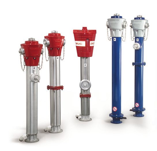
HAWLE - H4 Überflurhydranten
DE
EN
IT
HAWLE. MADE FOR GENERATIONS.
Sehr geehrter Kunde,

herzlichen Glückwunsch, dass Sie sich für die Hawle H4 Überflurhydranten
entschieden haben.

Sie haben ein hochwertiges Hawle Produkt erworben, das bei jeder
Produktionsstufe mehreren Qualitätsprüfungen und einer sorgfältigen
Warenausgangskontrolle unterzogen wurde.

Sollte es wider Erwarten dennoch zu einer Störung mit dieser Armatur kom-
men, verfügen Sie in jedem Fall über eine 10-jährige Hawle Garantie. Diese
Garantie kann selbstverständlich jederzeit geltend gemacht werden.

Dieses Dokument erläutert die Vorbereitungen für den Gebrauch und grundle-
genden Einbau, um das Produkt optimal nutzen zu können.

Sämtliche Texte, Grafiken, Fotos, Marken, Logos, Bilder, einschließlich
Design, Aussehen und Anordnung sind Eigentum von
E. Hawle Armaturenwerke GmbH.

Die Hawle - Wortmarke sowie das Hawle Logo sind durch Urheberrechts-,
Patent- und Markengesetze sowie durch verschiedene andere Gesetze für
das geistige Eigentum und gegen unlauterem Wettbewerb geschützt.

2 | HAWLE
ALLGEMEINE HINWEISE:
Die Einbauanleitung gilt für alle Hawle H4 Überflurhydranten.

Die Montage von Hawle H4 Überflurhydranten hat ausschließlich durch
geschultes Personal nach den Regeln des Handwerks zu erfolgen. Bei der
Verlegung sind die gültigen Normen und Regelwerke sowie Unfallverhütungs-
vorschriften zu beachten.
Manipulation an Produkten (Änderungen, Reparatur, Austausch von Bauteilen,
Lösen von werksseitigen Verbindungen, usw.) sind nicht zulässig und bewir-
ken ein Erlöschen der Gewährleistungspflicht bzw. der Produkthaftung.

Lagerbedingungen:
Lagerung in der Original Hawle Verpackung bzw. mit den werksseitig montier-
ten Abdeckkappen zum Schutz vor Verschmutzung und Beschädigung.

Entsorgungshinweis:
Die Verpackung des Hawle H4 Überflurhydranten besteht ausschließlich aus
wiederverwertbaren Materialien.
Bitte führen Sie diese entsprechend sortiert wieder dem „Dualen System“ zu.

Die Werkstoffe sind gemäß ihrer Kennzeichnung wieder verwendbar.
Mit der Wiederverwendung, der stofflichen Verwertung oder anderen Formen
der Verwertung von Armaturen leisten Sie einen wichtigen Beitrag zum Schut-
ze unserer Umwelt.

Die Inhalte dieser Anleitung wurden nach bestem Wissen erstellt. Jedoch
können bei der Richtigkeit, Vollständigkeit und Aktualität der Inhalte Fehler
auftreten.
Wir möchten Sie bitten mit uns in diesem Fall Kontakt aufzunehmen, um diese
so schnell wie möglich zu korrigieren.

E. Hawle Armaturenwerke GmbH behält sich das Recht vor, diese Anleitung
nach eigenem Ermessen zu ändern oder zu modifizieren.

                                                                       DE
                                                                   HAWLE | 3
ABGÄNGE:

                                       TYP
 LAND           A (100 mm)      B (65 mm)      C (50 mm)
 Österreich     DIN 14319       DIN 14318      DIN 14317
 Deutschland    DIN 14319       DIN 14318      DIN 14317
 England        BS 336          BS 336         BS 336
 Italien        UNI             UNI            UNI
 Schweiz        DIN 14319       DIN 14318      DIN 14317
 Polen          DIN 14319       DIN 14318      DIN 14317
 Russland       Gost            Gost           Gost
 Norwegen       NOR             NOR            NOR

Durchflusscharakteristik, Kv-WERT min.
Kv-Wert für 2 x 65 mm		           > 200 m3/h
Kv-Wert für 1 x 65 mm & 2x 50 mm > 150 m3/h
Kv-Wert für 1 x 100 mm & 2x 65 mm > 200 m3/h

4 | HAWLE
MONTAGE
Vorbereitungsarbeiten Hydrant montieren Hydrantkopf drehbar
1 1 1
Empfehlung: Schieber vor Flansche kreuzweise
verschrauben bzw. Muffen- Schrauben am Spannring
Hydrant einbauen
verbindung herstellen lösen
2 2
2
Standfläche herstellen
Einbauhöhe beachten Hydrant ausreichend abstützen
(Umfahrhydrant: Sollbruchstelle Hydrantkopf in erforderliche
12 ±6 cm über Erdniveau) 3 Lage drehen
d 32 3
3
Sicker Pipe / Entleerungsleitung min.
Sicker Pipe oder Entleerungs- montieren - Sickerpackung Drehmoment
leitung 1” (1 - 3 m) vorbereiten anlegen - Druckprobe - Spülen 35 Nm
4 4 Schrauben festziehen
Achtung!
Sockelver-
schraubung
bei Guss-
hydrant
darf nicht
Flanschverbindung bzw. Muffen geöffnet
für Hydrantanschluss vorbereiten Baugrube auffüllen werden!
DE
HAWLE | 5INBETRIEBNAHME / WARTUNG (jährlich)
1 2 3
Überprüfen, ob Hydrant geschlossen Kappe entfernen Spülen
4 5 6
Auf Entleerungsgeräusche achten.
Hydrant schließen (Reparatur erforderlich?) Kappe montieren
6
6 | HAWLEMONTAGE
bei Bruch der Sollbruchstelle (Umfahrhydrant)
v1 4 7
Sichtkontrolle auf
Beschädigung und Betätigungskappe und Haube Anzugsmoment der Sollbruch-
Verschmutzung entfernen schrauben max. 60 Nm
2 5 8
Reserve-Sollbruchschrauben
Falls notwendig: Flansch entnehmen, nachbestellen und Haube und Betätigungskappe
reinigen wieder deponieren! montieren
3 6 9
Inbetriebnahme
Wartung
O-Ring einlegen Hydrantsäule aufsetzen
DE
HAWLE | 71085
1085-CPD-0022
2010
EN 14384, EN 1074-6
Überflurhydrant starr:
5140H4, 5151H4, 5051H4, 5053H4
Typ C
DN 80 und DN 100
PN 16
Schließrichtung: im Uhrzeigersinn
Anzahl der Umdrehungen: 15
Moment (MOT, mST): Bereich 2(250)
Einlaufflansch: EN 1092-1 / 1092-2
Entleerung (Menge, Zeit):1
ENTLEERUNG UNDICHT oder
VENTILKEGEL WECHSELN
Wenn Entleerung undicht, entfällt Pkt. 5
Wird Ventilkegel gewechselt, entfällt Pkt. 4
Zuleitung schließen
Hydrant vollständig öffnen
5
2 Betätigungsgarnitur (BG)
herausnehmen,
Ventilkegel wechseln BG
in Führung geben,
Kopf aufsetzen,
Schrauben festziehen
Betätigungskappe und Haube
entfernen 6
3
Haube und Betätigungskappe
montieren
Schrauben lösen, Kopf abnehmen
7
4
180°
Betätigungsgarnitur (BG) herausnehmen,
Position der Betätigungsgarnitur
markieren, diese um 180° drehen. Hydrant schließen; Zuleitung öffnen
Kopf aufsetzen, Schrauben festziehen
8 Inbetriebnahme
oder Wartung
DE
HAWLE | 91085
1085-CPD-0023
2010
EN 14384, EN 1074-6
Umfahrhydrant:
5195H4, 5196H4, 5095H4, 5096H4
Typ A
DN 80 und DN 100
PN 16
Schließrichtung: im Uhrzeigersinn
Anzahl der Umdrehungen: 15
Moment (MOT, mST): Bereich 2(250)
Einlaufflansch: EN 1092-1 / 1092-2
Entleerung (Menge, Zeit):1
ENTLEERUNG UNDICHT oder
VENTILKEGEL WECHSELN
Wenn Entleerung undicht, entfällt Pkt. 5
Zuleitung schließen Wird Ventilkegel gewechselt, entfällt Pkt. 4
Hydrant vollständig öffnen
2 6
Sollbruchschrauben entfernen Spindelhalter arretieren
Hydrantsäule abnehmen Federvorstecker einstecken
3 7
Federvorstecker entfernen Hydrantsäule aufsetzen
Spindelhalter aus Verankerung drehen
8
4
max.60 Nm
Sollbruchschrauben anziehen
Betätigungsgarnitur um 180° drehen 9
oder
5
Hydrant schließen; Zuleitung öffnen
Betätigungsgarnitur (BG) herausnehmen, 10 Inbetriebnahme
Ventilkegel wechseln BG in Führung geben Wartung
DE
HAWLE | 111085
1085-CPD-0024
2010
EN 14384, EN 1074-6
Umfahrhydrant mit Fallmantel:
5185, 5186
Typ A mit Fallmantel
DN 80 und DN 100
PN 16
Schließrichtung: im Uhrzeigersinn
Anzahl der Umdrehungen: 15
Moment (MOT, mST): Bereich 2(250)
Einlaufflansch: EN 1092-1
Entleerung (Menge, Zeit):1
ENTLEERUNG UNDICHT oder
VENTILKEGEL WECHSELN
Wenn Entleerung undicht, entfällt Pkt. 5
Zuleitung schließen Wird Ventilkegel gewechselt, entfällt Pkt. 4
Hydrant vollständig öffnen
2 6
Sollbruchschrauben entfernen Spindelhalter arretieren
Hydrantsäule abnehmen Federvorstecker einstecken
3 7
Federvorstecker entfernen Hydrantsäule aufsetzen
Spindelhalter aus Verankerung drehen
8
4
max. 60 Nm
Sollbruchschrauben anziehen
Betätigungsgarnitur um 180° drehen 9
oder
5
Hydrant schließen; Zuleitung öffnen
Betätigungsgarnitur (BG) herausnehmen, 10 Inbetriebnahme
Ventilkegel wechseln BG in Führung geben Wartung
DE
HAWLE | 13Dear Customer, congratulations on your decision to purchase the Hawle H4 above ground hydrant! You have purchased a high-grade Hawle product that has been subjected to several quality tests at each production stage, as well as to severe outgoing goods inspection. If, contrary to all expectations, this valve should be defective, you can certainly make use of our 10 years Hawle warranty. Of course, this warranty can be invoked any time. This document explains the preparations for use as well as the basic installation to ensure the optimum utilization of its properties. Any and all texts, graphic charts, photos, brands, logos, images, including the design, appearance and arrangement of such contents are the property of E. Hawle Armaturenwerke GmbH. The Hawle mark designation as well as the Hawle logo are protected by the Copyright Act, the Patent Act and the Trademark Act, as well as by various other acts regulating intellectual property and unfair competition. 14 | HAWLE
GENERAL NOTES:
This installation manual applies to all Hawle H4 above ground hydrants.

Hawle H4 above ground hydrants may be installed only by trained personel
according to the rules of the trade. For installation the applicable standards and
regulations as well as the provisions for the prevention of accidents shall be
complied with.
The manipulation of products (modification, repair, exchange of components,
loosening of factory-made connections, etc.) is not permitted and will void the
warranty and/or product liability.

Storage conditions:
Please store the product in the original Hawle packaging and/or with the factory-
mounted cover caps to protect it against dirt and damage.

Disposal note:
The packaging of the Hawle H4 above ground hydrant consists exclusively of
recyclable materials.
Please recycle them, properly sorted, to the „Dual System“.

The materials can be re-used according to their identification.
By re-using, material recycling or other ways of recycling of valves you
contribute significantly to the protection of our environment.

Although the contents of this manual have been prepared with utmost care,
there may still be errors regarding the correctness, completeness, and topicality
thereof.
In this case, please contact us so we are able to correct any such error as quickly
as possible.

E. Hawle Armaturenwerke GmbH reserves the right to change or modify this
manual at its own discretion.

                                                                             EN
                                                                       HAWLE | 15
HYDRANT CONNECTION COUPLING:
TYPE
COUNTRY A (100 mm) B (65 mm) C (50 mm)
Austria DIN 14319 DIN 14318 DIN 14317
Germany DIN 14319 DIN 14318 DIN 14317
England BS 336 BS 336 BS 336
Italy UNI UNI UNI
Switzerland DIN 14319 DIN 14318 DIN 14317
Poland DIN 14319 DIN 14318 DIN 14317
Russia Gost Gost Gost
Norway NOR NOR NOR
Valve flow coefficient (Kv-VALUE min.)
Kv-value for 2 x 65 > 200 m3/h
Kv-value for 1 x 65 & 2x 50 > 150 m3/h
Kv-value for 1 x 100 & 2x 65 > 200 m3/h
16
16 | HAWLEASSEMBLY
Preperatory work Hydrant assembly Rotation of the hydrant head
1 1 1
Advice: install a gate valve bolt the flanges crosswise or
loosen the bolts at the
before the hydrant connect the sockets
tension ring
2 2
2
prepare a base. pay attention to
the installation height (break-away support the hydrant
rotate the hydrant head to
hydrant:break-away line 12 ±6 cm
3 the required position
above of the ground level)
3
3
Sicker-Pipe or prepare a Sicker-Pipe / assemble the drainage min.
pipe - fit on the rubble drain - torque
drainage pipe 1“ (1 - 3 m)
pressure test - flush 35 Nm
4 4 tighten the bolts
Caution!
It´s not
allowed to
open the
prepare a flange connection or bolts of the
sockets base flange!
for the hydrant assembly backfill the excavation
EN
17
HAWLE | 17OPERATION / MAINTENANCE (annual)
1 2 3
check, if the hydrant is closed remove the cap flush
4 5 6
pay attention to the drainage
close the hydrant noise (repair necessary?) put the cap back on
18
18 | HAWLEASSEMBLY
Damage of the break away line (break away hydrant)
v1 4 7
examination of the
break-away line remove the cap and the torque for tightening bolts:
(damage, soiling, etc.) operating nut max. 60 Nm
2 5 8
remove spare bolts, re-order
if necessary: clean the flange bolts, replace them in cap assemble the cap and the
operating nut
3 6 9
operation
maintenance
insert O ring connect stand pipe
with the base
EN
19
HAWLE | 191085
1085-CPD-0022
2010
EN 14384, EN 1074-6
Hydrant rigid:
5140H4, 5151H4, 5051H4, 5053H4
Type C
DN 80 to DN 100
PN 16
Closing direction: clockwise
Number of turns: 15
Operation torque: region 2 (MOT 250)
Flange inlet: EN 1092-1 / 1092-2
Drainage (quantity, time):1
DRAINAGE UNTIGHT or CHANGE
OF THE VALVE PLUG
If the drainage is untight, skip step 5.
If the valve plug has to be changed, skip step 4.
close the supply
open the hydrant completely 5
2 take out the operating
controls, change
the valve plug, insert
the operating control,
put head in place again,
tighten the bolts
remove the operating nut
and the cap 6
3
assemble the cap and the
operating nut
loosen the bolts, remove the head
7
4
180°
take out the operating controls, mark
the position of the operating controls,
rotate it by 180°. Put the hydrant head close the hydrant; open the supply
on, tighten the bolts. 8 operation
or maintenance
EN
21
HAWLE | 211085
1085-CPD-0023
2010
EN 14384, EN 1074-6
Hydrant-break away:
5195H4, 5196H4, 5095H4, 5096H4
Type A
DN 80 and DN 100
PN 16
Closing direction: clockwise
Number of turns: 15
Operation torque: region 2 (MOT 250)
Flange inlet: EN 1092-1 / 1092-2
Drainage (quantity, time):1
DRAINAGE UNTIGHT or CHANGE
OF THE VALVE PLUG
If the drainage is untight, skip step 5.
close the supply If the valve plug has to be changed, skip step 4.
open the hydrant completely
2 6
remove the bolts Lock the spindle housing
detach the stand pipe connect the spring clip
3 7
remove the spring clip; turn the spindle hous- connect the stand pipe with the base
ing out of the anchoring
8
4
max.60 Nm
tighten the bolts
rotate the operating controls by 180° 9
or
5
close the hydrant, open the supply
take out the operating controls, change
10 operation
the valve plug*, insert the operating control maintenance
EN
23
HAWLE | 231085
1085-CPD-0024
2010
EN 14384, EN 1074-6
Hydrant with drop jacket:
5185, 5186
Type A with drop jacket
DN 80 and DN 100
PN 16
Closing direction: clockwise
Number of turns: 15
Operation torque: region 2 (MOT 250)
Flange inlet: EN 1092-1
Drainage (quantity, time):1
DRAINAGE UNTIGHT or CHANGE
OF THE VALVE PLUG
If the drainage is untight, skip step 5.
close the supply If the valve plug has to be changed, skip step 4.
open the hydrant completely
2 6
remove the bolts Lock the spindle housing
detach the stand pipe connect the spring clip
3 7
remove the spring clip; turn the spindle hous- connect the stand pipe with the base
ing out of the anchoring
8
4
max. 60 Nm
tighten the bolts
rotate the operating controls by 180° 9
or
5
close the hydrant, open the supply
take out the operating controls, change
10 operation
the valve plug*, insert the operating control maintenance
EN
25
HAWLE | 25Gentile cliente, complimenti per aver scelto un idrante a colonnina Hawle H4. Lei ha acquistato un prodotto Hawle di altissima qualità, il quale è stato sottoposto, in ogni stadio della produzione, a svariati controlli di qualità e ad una severa ispezione finale. Qualora, comunque, contro ogni aspettativa, lei dovesse verificare una anomalia su questa apparecchiatura, potrà disporre in ogni caso della garanzia decennale Hawle, la quale potrà essere naturalmente fatta valere in qualsiasi momento. Il presente documento spiega la procedura di preparazione per l‘uso e genericamente per l‘installazione al fine di poter sfruttare in modo ottimale le caratteristiche. Tutti i testi, la grafica, le fotografie, i marchi, i logo, le immagini, incluso il design, l‘aspetto e la disposizione di tali contenuti sono di proprietà esclusiva di E. Hawle Armaturenwerke GmbH. Il marchio denominativo Hawle come anche il logo Hawle sono protetti da copyright, da normative sui brevetti e sui marchi nonché da diverse altre norme relative alla proprietà intellettuale ed alla concorrenza sleale. 26 | HAWLE
INDICAZIONI GENERALI:
Le istruzioni di montaggio sono valide per tutti gli idranti a colonnina Hawle H4.

Il montaggio degli idranti a colonnina Hawle H4 deve essere eseguito esclusi-
vamente da personale addestrato secondo le regole dell‘artigianato. Durante
la posa sono da osservare le vigenti norme e regolamentazioni nonché le
leggi relative alla prevenzione degli infortuni.
Le manipolazioni di prodotti (modifiche, riparazioni, sostituzione di compo-
nenti, smontaggio di connessioni effettuate dal costruttore, ecc.) non sono
consentite e causano l‘estinzione dell‘obbligo di garanzia e/o della responsa-
bilità per danno da prodotti difettosi.

Condizioni di stoccaggio:
Conservare nell‘imballaggio originale Hawle e/o con le calotte di copertura appli-
cate dal costruttore a protezione dallo sporco e dai danneggiamenti.

Indicazioni per lo smaltimento:
L‘imballaggio dell‘idrante a colonnina Hawle H4 è costituito esclusivamente da
materiali riciclabili.
Vi preghiamo di far pervenire questi materiali, adeguatamente selezionati, al
„sistema duale“ di ritiro e recupero degli imballaggi usati.

I materiali sono riutilizzabili conformemente al loro contrassegno.
Riciclando e riutilizzando questi materiali, oppure mediante altre forme di riciclo
delle apparecchiature, contribuirete in maniera determinante alla salvaguardia
dell‘ambiente.

I contenuti di queste istruzioni sono stati realizzati con la massima cura. L‘esat-
tezza, la completezza e l‘attualità sono comunque suscettibili di errori nei loro
contenuti.
In tal caso, Vi preghiamo di contattarci al fine di consentirci di correggere questi
errori nel più breve tempo possibile.

E. Hawle Armaturenwerke GmbH si riserva il diritto di modificare o ritoccare
queste istruzioni a propria discrezione.

                                                                                 IT
                                                                         HAWLE | 27
USCITE:
TIPO
PAESE A (100 mm) B (65 mm) C (50 mm)
Austria DIN 14319 DIN 14318 DIN 14317
Germania DIN 14319 DIN 14318 DIN 14317
Regno Unito BS 336 BS 336 BS 336
Italien UNI UNI UNI
Svizzera DIN 14319 DIN 14318 DIN 14317
Polonia DIN 14319 DIN 14318 DIN 14317
Russia Gost Gost Gost
Norvegia NOR NOR NOR
Valore Kv (flusso) min.
Valore Kv per 2 x 65 mm > 200 m3/h
Valore Kv per 1 x 65 mm & 2x 50 mm > 150 m3/h
Valore Kv per 1 x 100 mm & 2x 65 mm > 200 m3/h
28
28 | HAWLEMONTAGGIO
Preparativi Spostamento dell‘idrante Testata girevole
1 1 1
Suggerimento: installare una Avvitare le flange in modo
incrociato e/o collegare il Allentare le viti dell‘anello di
saracinesca prima dell‘idrante
manicotto tensione
2 2
2
Creare un piano d‘appoggio.
Tenere conto dell‘altezza di Puntellare bene l‘idrante
Girare la testata verso la
montaggio (Rottura prestabilita
3 posizione desiderata
a 12 + 6 cm da terra)
3
3
Sicker-Pipe / Preparare il tubo Sicker-Pipe / Montare il tubo di momento di
di drenaggio da 1“ (1-3 m) drenaggio con la sua ghiaia – prova di torsione
pressione – sciacquare min. 35 Nm
4 4 Fissare le viti
Attenzione!
Il collegamen-
to flangiato
degli idranti
in ghisa
non deve
Preparare flange/manicotti per il essere
collegamento con l‘idrante Riempire la fossa aperto!
IT
29
HAWLE | 29MESSA IN OPERA MANUTENZIONE (annuale)
1 2 3
Accertarsi che l’idrante sia chiuso Togliere il tappo Sciacquare
4 5 6
Ascoltare se ci sono rumori di
Richiudere l’idrante svuotamento (Riparazione?) Rimontare il tappo
30
30 | HAWLEMONTAGGIO
Riparazione dell’idrante a rottura prestabilita
v1 4 7
Controllo a vista per
danni e sporcizia Togliere tappo d’azionamento e Momento di torsione
coperchio delle viti max. 60 Nm
2 5 8
Staccare le viti di riserva
Se necessario pulire la flangia (riordinarle!) e richiudere! Montare il coperchio e il tappo
d’azionamento
3 6 9
Messa in opera
e manutenzione
Inserire l’O-ring Reinserire la colonna
IT
31
HAWLE | 311085
1085-CPD-0022
2010
EN 14384, EN 1074-6
Idrante sopra-suolo rigido:
5140H4, 5151H4, 5051H4, 5053H4
Tipo C
DN 80 e DN 100
PN 16
Chiusura: in senso orario
Numero dei giri: 15
Momento di torsione: Regime 2 (250)
Flangia di collegamento: EN 1092-1 / 1092-2
Svuotamento (quantità, tempo):1
PERDITE AL DRENAGGIO
O SOSTITUZIONE CONO
Se il drenaggio perde, Nr.5 è tralasciato
Se viene sostituito il cono, Nr. 4 è tralasciato
Chiudere l’alimentazione e aprire
l’idrante completamente
5
2 Togliere l’asta di
comando, sostituire
il cono, riporre nella
guida l’asta, rimet-
tere il coperchio,
chiudere le viti.
togliere tappo d’azionamento
e coperchio 6
3
Rimontare coperchio
e tappo d’azionamento
Allentare le viti e togliere il coperchio
7
4
180°
Segnare la posizione dell’asta
di comando e girarla di 180°.
Rimettere il coperchio Chiudere l’idrante, aprire l’alimentazione
e tirare le viti
8 Messa in opera
oppure e manutenzione
IT
33
HAWLE | 331085
1085-CPD-0023
2010
EN 14384, EN 1074-6
Idrante a rottura prestabilita:
5195H4, 5196H4, 5095H4, 5096H4
Tipo A
DN 80 e DN 100
PN 16
Chiusura: in senso orario
Numero dei giri: 15
Momento di torsione: Regime 2 (250)
Flangia di collegamento: EN 1092-1 / 1092-2
Svuotamento (quantità, tempo):1
PERDITE AL DRENAGGIO
O SOSTITUZIONE CONO
Se il drenaggio perde, Nr.5 è tralasciato
Chiudere l’alimentazione e aprire Se viene sostituito il cono, Nr. 4 è tralasciato
l’idrante completamente
2 6
Togliere le viti di rottura e staccare la Fissare la molletta e
colonna reintrodurre il mandrino
3 7
Togliere la molletta e staccare Rimettere la colonna dell’idrante
il mandrino dalla sede
8
4
max.60 Nm
Fissare le viti della rottura prestabilita
Girare l’asta di comando di 180° 9
oppure
5
Chiudere l’idrante; aprire l’alimentazione
Togliere l’asta di comando, sostituire
10 Messa in opera
il cono, riporre nella guida l’asta e manutenzione
IT
35
HAWLE | 351085
1085-CPD-0024
2010
EN 14384, EN 1074-6
Idrante esterno con accesso rapido:
5185, 5186
Tipo A con calotta
DN 80 e DN 100
PN 16
Chiusura: in senso orario
Numero dei giri: 15
Momento di torsione: Regime 2 (250)
Flangia di collegamento: EN 1092-1 / 1092-2
Svuotamento (quantità, tempo):1
PERDITE AL DRENAGGIO
O SOSTITUZIONE CONO
Se il drenaggio perde, Nr.5 è tralasciato
Chiudere l’alimentazione e aprire Se viene sostituito il cono, Nr. 4 è tralasciato
l’idrante completamente
2 6
Togliere le viti di rottura e staccare la Fissare la molletta e
colonna reintrodurre il mandrino
3 7
Togliere la molletta e staccare Rimettere la colonna dell’idrante
il mandrino dalla sede
8
4
max.60 Nm
Fissare le viti della rottura prestabilita
Girare l’asta di comando di 180° 9
oppure
5
Chiudere l’idrante; aprire l’alimentazione
Togliere l’asta di comando, sostituire
10 Messa in opera
il cono, riporre nella guida l’asta e manutenzione
IT
37
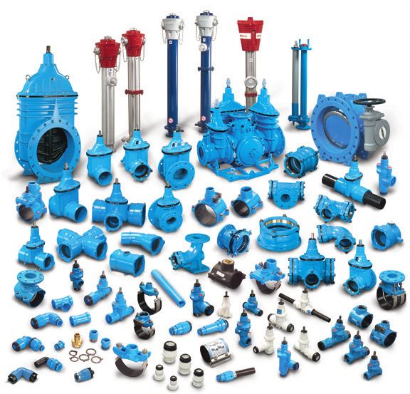
HAWLE | 37HAWLE, THE CLEVER CHOICE FOR U HAWLE ist ein führender Hersteller von Armaturen für die Was- ser-, Abwasser- und Gasnetzwerke mit zwei Fertigungsstätten in Österreich. HAWLE bemüht sich um jeden einzelnen Kunden, damit dessen Be- dürfnisse mit individuellen Lösungen befriedigt werden. Ein großes Programm mit hochwertigen Produkten ist daher für uns selbstver- ständlich. Vom ½" Fitting bis zum DN 600 Schieber hat HAWLE sämt- liche Armaturen und Verbindungsstücke für den Bau und Betrieb einer Wasserleitung verfügbar. Einige Beispiele aus unserem kompletten Produktsortiment: • Absperrschieber mit Verbindungen für alle Rohrarten • Kombischieber für Rohrleitungskreuzungen • Hydranten • Hausanschlussarmaturen • Regelventile In modernsten Produktionsstätten werden die HAWLE-Produkte aus- schließlich in Europa produziert, woher auch mehr als 98 % aller Rohstoffe kommen. Die HAWLE-Produktion zeichnet sich durch per- fekt ausgebildete Mitarbeiter und enorme Fertigungstiefe aus. Die lü- ckenlose Überwachung von Qualität und Funktionsfähigkeit ist durch die Eigenfertigung der meisten Teilprodukte garantiert. Um die rasche Bereitstellung der Produkte zu sichern, verfügt HAWLE über ein ausgezeichnetes Netz an Lagern und Händlern, die wö- chentlich beliefert werden. Zusätzlich sind im Zentrallager in Fran- kenmarkt auf mehr als 10.000 Palettenstellplätzen etwa eine Milli- on Fertigprodukte zum sofortigen Abruf eingelagert. 38 | HAWLE
UNINTERRUPTED WATER SUPPLY

                         HAWLE | 39
Ausgabe 03. 2019
Art.-Nr.: 5019632
Gedruckt auf umweltfreundlichem, chlorfrei gebleichtem und alterungsbeständigem Papier.
E. Hawle Armaturenwerke GmbH
Wagrainer Stra ße 13 Tel.: +43 (0)7672 72576-0 E-mail: hawle@hawle.at
4840 Vöcklabruck Fax.: +43 (0)7672 78464 www.hawle.comSie können auch lesen