GM - Miniaturmagnet Datenblätter - GM - Miniature solenoid - Logo Isliker Magnete
←
→
Transkription von Seiteninhalten
Wenn Ihr Browser die Seite nicht korrekt rendert, bitte, lesen Sie den Inhalt der Seite unten
ISLIKER MAGNETE

 GM - Miniaturmagnet
 Datenblätter

 GM - Miniature solenoid
 Datasheets

ISLIKER MAGNETE AG - CH-8450 Andelfingen - Tel. +41 (0)52 305 25 25 - info@islikermagnete.ch - www.islikermagnete.ch
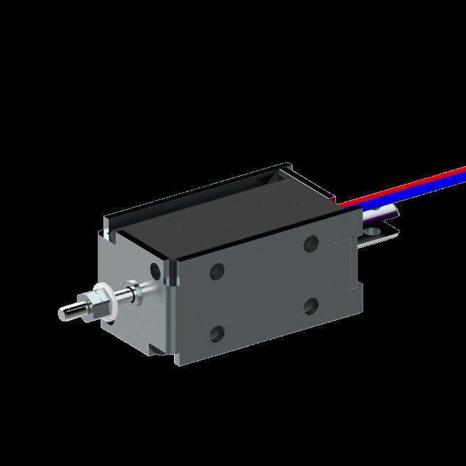
GM		            Miniaturmagnet Übersicht
GM		            Miniature solenoid overview
                                                                                    ISLIKER MAGNETE

                                          Übersicht / Overview

                                      Dimensionen           Hub                 Fmin
                  Typ
                                      Dimensions            Stroke              Fmin
                  Type
                                      [mm]                  [mm]                [N]

                  GM-20.05            23 x 20 x 40          5                   1.9

                  GM-26.08            30 x 26 x 50          8                   3.5

                  GM-35.10            40 x 35 x 60          10                  7

ISLIKER MAGNETE AG - CH-8450 Andelfingen - Tel. +41 (0)52 305 25 25 - info@islikermagnete.ch - www.islikermagnete.ch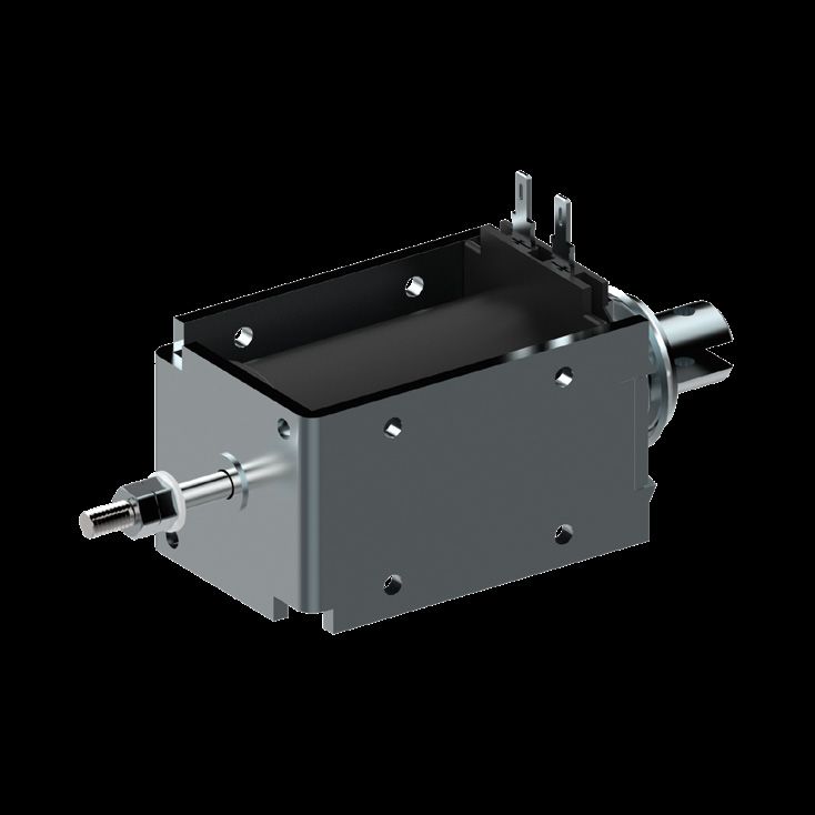
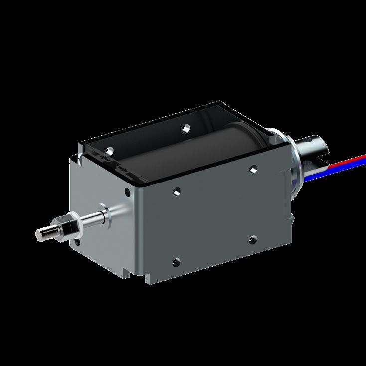
GM-20.05 Miniaturmagnet
GM-20.05 Miniature solenoid
ISLIKER MAGNETE
20
6.8
10 1.7
Ausführung I Ausführung II
Execution I Execution II
11.5
4
M4
10 M
5
3.2
O7
20
12
14
Stossseite Zugseite
23 Push side 10 20 Pull side 14
Magnet bestromt gezeichnet
Solenoid illustrated in energised position
Hub / stroke = 5
5
2
Max. Einschraubtiefe der 3.
M2.5
Befestigungsschrauben O
ist 2 mm
O 15
O7
Max. depth of thread
for fixing screw = 2 mm
10
0.5 10 Mit Federrückstellung
15 41 14 with return spring
10
ED [%] 100 40 25 15 5 Duty cycle [%]
9
Die Spieldauer für The max. duty cycle
die Berechnung der time to determine the
8
Kraft (Fn) / Force Fn [N]
Einschaltdauer beträgt duty cycle is 30 sec.
5%
30 sec.
7
Hubarbeit [Ncm] 1.0 1.8 2.0 2.6 3.8 Work done [Ncm]
6
15% El. Leistung [W] 8.2 19 27 47 145 Power [W]
5 (P20) (P20)
25%
4
Anzugszeit [ms] 45 44 42 41 40 Operating time [ms]
40%
Abfallzeit [ms] 30 27 24 21 18 Release time [ms]
3
(+20°C, betriebswarm, (+20°C, operating
F2.0 100% bei Belastung mit 70% temperature, with a
2
der entsprechenden load equal to 70% of
F1.3 Magnetkraft) the solenoid force)
Federcharakteristik
1 Spring characteristic
F0.6
0 = Nicht Standard / not standard
0 1 2 3 4 5 6 7 8
Hub / stroke [mm]
2021-07 1.4
ISLIKER MAGNETE AG - CH-8450 Andelfingen - Tel. +41 (0)52 305 25 25 - info@islikermagnete.ch - www.islikermagnete.ch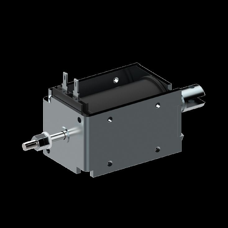
GM-20.05                  Miniaturmagnet
GM-20.05                  Miniature solenoid
                                                                                                           ISLIKER MAGNETE

Spezifikationen                                                                                                        Specifications

     Funktion                                  ziehend / stossend                          pull / push                 Operation
     Vorzugs-Nennspannung                                       24VDC (max. 50VDC)                                     Preferred rated voltage
     Isolierstoffklasse                                        B (130°C) DIN VDE 0580                                  Class of insulation
     Prüfspannung                                                     EN 60664-1                                       Test voltage
     Überspannungskategorie                                               III                                          Surge category
     Schutzart                                                      IP00 (IEC 60529)                                   Degree of protection
     El. Anschlussart                   Steckzungen 2.8 x 0.8 DIN 46342-1           2.8 x 0.8 Tabs DIN 46342-1         Electrical termination
                                            Litzen (300mm), AWG22                 Lead wires (300mm), AWG22
     Oberflächenbehandlung             Gehäuse verzinkt & blau passiviert,     Solenoid housing zinc plated & tri-     Surface treatment
                                             Anker hartverchromt               valent chrome passivated, plunger
                                                                                       hard chrome-plated
     bewegte Masse                                                      0.013kg                                        Moving mass
     Total Magnetgewicht                                                0.075kg                                        Total weight of solenoid

Bestellbeispiel                                                                                            Ordering specification

                                         GMs - 20.05 - 100 U - 24 I F 0.6 "D"
Gleichstrom-Miniatur-Magnet                                                                                Type GM: D.C. Miniature solenoid
s:      mit Stossstange                                                                                    s:     with push rod
        ohne Index keine Stossstange                                                                              without push rod - no index
Baugrösse                                                                                                  Size
Nennhub des Magneten in mm                                                                                 Rated stroke of solenoid in mm
Einschaltdauer (ED) in %                                                                                   Duty cycle in %
U: Universalanschluss                                                                                      U: Universal termination
W: Litzenanschluss                                                                                         W: Lead wire
Spannung in Volt                                                                                           Voltage
I       Anschlüsse auf Stossseite                                                                          I      Electrical termination on push side
II      Anschlüsse auf Zugseite                                                                            II     Electrical termination on pull side
Mit Rückstellfeder                                                                                         With return-spring assembly
Ohne Rückstellfeder kein Index                                                                             Without spring - no index
Index der Federkennlinie                                                                                   Index of return-spring
"D": mit Dämpfung                                                                                          "D": with damping
     (nur mit Feder möglich)                                                                                    (only possible with spring)
     ohne Index keine Dämpfung                                                                                  Without damping - no index

Bemerkungen                                                                  Notes

1) Magnete hergestellt und geprüft nach DIN VDE 0580                         1) Solenoids manufactured and tested according to DIN VDE 0580

2) Magnetkraft betriebswarm gemessen bei 20°C                                2) Forces indicated measured at 20°C ambient and operating
   Umgebungstemperatur, waagrechter Bewegungsrichtung                           temperature with 90% of its rated voltage, in horizontal position
   mit 90% Nennspannung

3) Die Magnethaftkraftwerte gelten nur als Referenzwerte                     3) Force values for reference only and can differ
   und können infolge Toleranzen um ±10% abweichen                              ±10% as a result of natural dispertion

4) Sonderausführungen sind lieferbar                                         4) Special designs are available

5) Änderungen vorbehalten - Abbildungen unverbindlich                        5) All specifications subject to change without notice

6) RoHS konform, frei von Halogenen (PVC)                                    6) Compliant with RoHS; free of halogenes (PVC)

7) Unsere „Technischen Erläuterungen“ geben                                  7) Our „Technical Explanations“ provide information about the use of
   Auskunft über den Einsatz von Magneten sowie zu                              solenoids as well as to general installation and safety instructions
   allgemeinen Montage- und Sicherheitshinweisen
                                                                                                                                                        2021-07 1.4

ISLIKER MAGNETE AG - CH-8450 Andelfingen - Tel. +41 (0)52 305 25 25 - info@islikermagnete.ch - www.islikermagnete.ch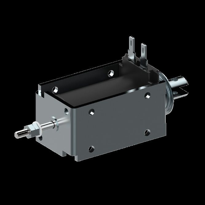
GM-26.08 Miniaturmagnet
GM-26.08 Miniature solenoid
ISLIKER MAGNETE
26 6.2
Ausführung I Ausführung II
10 Execution I 1.2 Execution II
11.5
4
M4
M
12
4
4.2
O9
26
18
20
Stossseite Zugseite
30 Push side 10 30 Pull side 20
Magnet bestromt gezeichnet
Solenoid illustrated in energised position
Hub / stroke = 8
8
.2
O3
Max. Einschraubtiefe der
Befestigungsschrauben
ist 3 mm
O 20
O7
M3
Max. depth of thread
for fixing screw = 3 mm 12
0.5 15 Mit Federrückstellung
20 50 20 with return spring
20
ED [%] 100 40 25 15 5 Duty cycle [%]
18
Die Spieldauer für The max. duty cycle
5% die Berechnung der time to determine the
16 Einschaltdauer beträgt duty cycle is 30 sec.
Kraft (Fn) / Force (Fn) [N]
30 sec.
14
Hubarbeit [Ncm] 2.8 4.8 5.6 7.2 12.4 Work done [Ncm]
12
El. Leistung [W] 12 28 44 70 200 Power [W]
(P20) (P20)
10
15%
8 Anzugszeit [ms] 65 62 60 57 55 Operating time [ms]
25% Abfallzeit [ms] 45 40 35 30 25 Release time [ms]
40%
6 (+20°C, betriebswarm, (+20°C, operating
F5.0 bei Belastung mit 70% temperature, with a
4 der entsprechenden load equal to 70% of
100% Magnetkraft) the solenoid force)
F3.0
Federcharakteristik
2
Spring characteristic = Nicht Standard / not standard
F0.8
0
0 2 4 6 8 10 12
2021-07 1.4
Hub / stroke [mm]
ISLIKER MAGNETE AG - CH-8450 Andelfingen - Tel. +41 (0)52 305 25 25 - info@islikermagnete.ch - www.islikermagnete.ch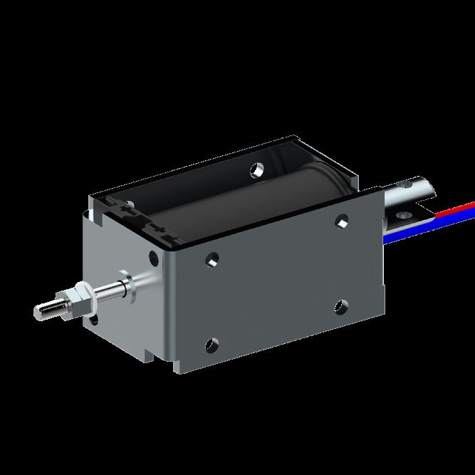
GM-26.08                  Miniaturmagnet
GM-26.08                  Miniature solenoid
                                                                                                           ISLIKER MAGNETE

Spezifikationen                                                                                                        Specifications

     Funktion                                  ziehend / stossend                          pull / push                 Operation
     Vorzugs-Nennspannung                                       24VDC (max. 50VDC)                                     Preferred rated voltage
     Isolierstoffklasse                                        B (130°C) DIN VDE 0580                                  Class of insulation
     Prüfspannung                                                     EN 60664-1                                       Test voltage
     Überspannungskategorie                                               III                                          Surge category
     Schutzart                                                      IP00 (IEC 60529)                                   Degree of protection
     El. Anschlussart                   Steckzungen 2.8 x 0.8 DIN 46342-1           2.8 x 0.8 Tabs DIN 46342-1         Electrical termination
                                            Litzen (300mm), AWG20                 Lead wires (300mm), AWG20
     Oberflächenbehandlung             Gehäuse verzinkt & blau passiviert,     Solenoid housing zinc plated & tri-     Surface treatment
                                             Anker hartverchromt               valent chrome passivated, plunger
                                                                                       hard chrome-plated
     bewegte Masse                                                      0.027kg                                        Moving mass
     Total Magnetgewicht                                                0.180kg                                        Total weight of solenoid

Bestellbeispiel                                                                                            Ordering specification

                                         GMs - 26.08 - 100 U - 24 I F 0.8 "D"
Gleichstrom-Miniatur-Magnet                                                                                Type GM: D.C. Miniature solenoid
s:      mit Stossstange                                                                                    s:     with push rod
        ohne Index keine Stossstange                                                                              without push rod - no index
Baugrösse                                                                                                  Size
Nennhub des Magneten in mm                                                                                 Rated stroke of solenoid in mm
Einschaltdauer (ED) in %                                                                                   Duty cycle in %
U: Universalanschluss                                                                                      U: Universal termination
W: Litzenanschluss                                                                                         W: Lead wire
Spannung in Volt                                                                                           Voltage
I       Anschlüsse auf Stossseite                                                                          I      Electrical termination on push side
II      Anschlüsse auf Zugseite                                                                            II     Electrical termination on pull side
Mit Rückstellfeder                                                                                         With return-spring assembly
Ohne Rückstellfeder kein Index                                                                             Without spring - no index
Index der Federkennlinie                                                                                   Index of return-spring
"D": mit Dämpfung                                                                                          "D": with damping
     (nur mit Feder möglich)                                                                                    (only possible with spring)
     ohne Index keine Dämpfung                                                                                  Without damping - no index

Bemerkungen                                                                  Notes

1) Magnete hergestellt und geprüft nach DIN VDE 0580                         1) Solenoids manufactured and tested according to DIN VDE 0580

2) Magnetkraft betriebswarm gemessen bei 20°C                                2) Forces indicated measured at 20°C ambient and operating
   Umgebungstemperatur, waagrechter Bewegungsrichtung                           temperature with 90% of its rated voltage, in horizontal position
   mit 90% Nennspannung

3) Die Magnethaftkraftwerte gelten nur als Referenzwerte                     3) Force values for reference only and can differ
   und können infolge Toleranzen um ±10% abweichen                              ±10% as a result of natural dispertion

4) Sonderausführungen sind lieferbar                                         4) Special designs are available

5) Änderungen vorbehalten - Abbildungen unverbindlich                        5) All specifications subject to change without notice

6) RoHS konform, frei von Halogenen (PVC)                                    6) Compliant with RoHS; free of halogenes (PVC)

7) Unsere „Technischen Erläuterungen“ geben                                  7) Our „Technical Explanations“ provide information about the use of
   Auskunft über den Einsatz von Magneten sowie zu                              solenoids as well as to general installation and safety instructions
   allgemeinen Montage- und Sicherheitshinweisen
                                                                                                                                                        2021-07 1.4

ISLIKER MAGNETE AG - CH-8450 Andelfingen - Tel. +41 (0)52 305 25 25 - info@islikermagnete.ch - www.islikermagnete.ch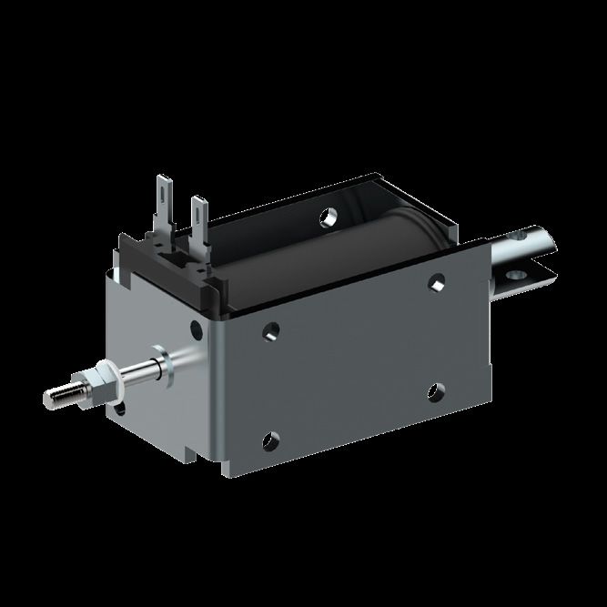
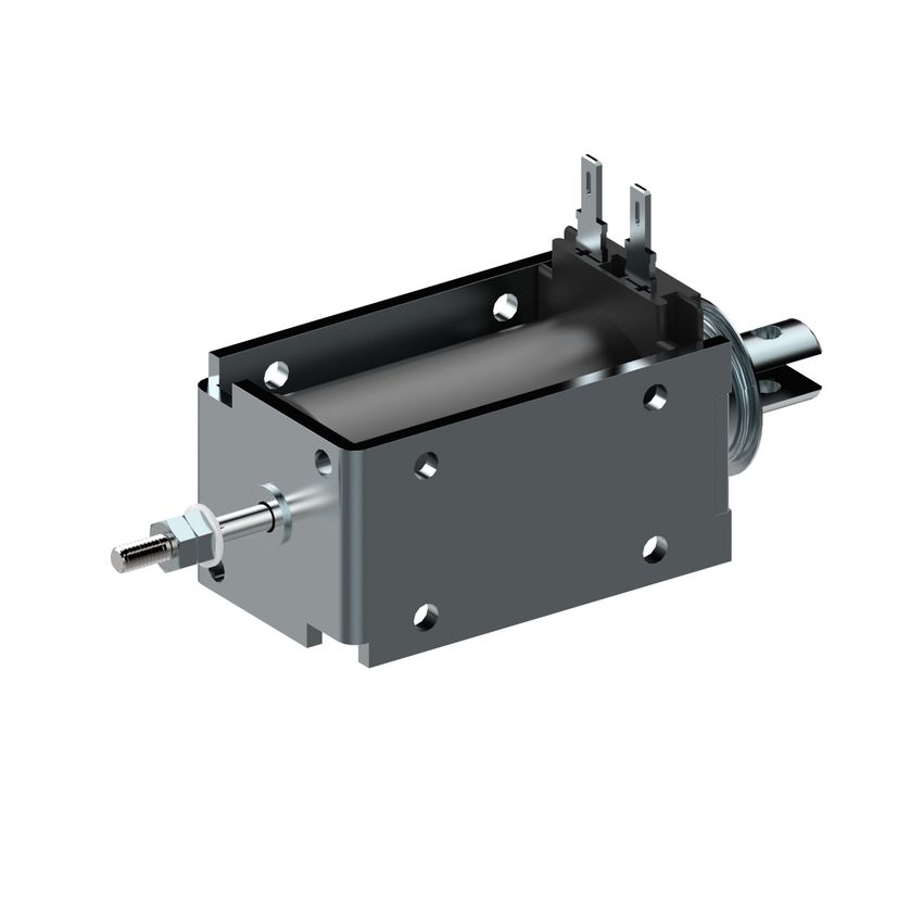
GM-35.10 Miniaturmagnet
GM-35.10 Miniature solenoid
ISLIKER MAGNETE
26 6.7
Ausführung I Ausführung II
10 Execution I 1.7 Execution II
4 11
4
4
M
M
12
4.2
O 12
35
25
28
Stossseite Zugseite
40 Push side 15 30 Pull side 28
Magnet bestromt gezeichnet
Solenoid illustrated in energised position
12
Hub / stroke = 10
3.2
Max. Einschraubtiefe der
O
Befestigungsschrauben
"D" O 30
O 24.5
ist 4 mm
O9
M4
Max. depth of thread
for fixing screw = 4 mm
15
0.5 20 Mit Federrückstellung
25 60 25 with return spring
40
ED [%] 100 40 25 15 5 Duty cycle [%]
35 Die Spieldauer für The max. duty cycle
die Berechnung der time to determine the
Kraft (Fn) / Force (Fn) [N]
5%
Einschaltdauer beträgt duty cycle is 30 sec.
30 30 sec.
25 Hubarbeit [Ncm] 7.5 12 17 21 32 Work done [Ncm]
15% El. Leistung [W] 17 42 66 111 350 Power [W]
20 (P20) (P20)
25%
15 Anzugszeit [ms] 110 100 85 80 75 Operating time [ms]
Abfallzeit [ms] 80 65 60 55 50 Release time [ms]
F11 40%
10 (+20°C, betriebswarm, (+20°C, operating
bei Belastung mit 70% temperature, with a
100%
der entsprechenden load equal to 70% of
F6.0
5 Federcharakteristik
Magnetkraft) the solenoid force)
F1.5 Spring characteristic
0 = Nicht Standard / not standard
0 2 4 6 8 10 12 14
Hub / stroke [mm]
2021-07 1.4
ISLIKER MAGNETE AG - CH-8450 Andelfingen - Tel. +41 (0)52 305 25 25 - info@islikermagnete.ch - www.islikermagnete.ch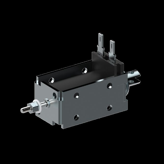
GM-35.10                  Miniaturmagnet
GM-35.10                  Miniature solenoid
                                                                                                           ISLIKER MAGNETE

Spezifikationen                                                                                                        Specifications

     Funktion                                  ziehend / stossend                          pull / push                 Operation
     Vorzugs-Nennspannung                                       24VDC (max. 50VDC)                                     Preferred rated voltage
     Isolierstoffklasse                                        B (130°C) DIN VDE 0580                                  Class of insulation
     Prüfspannung                                                     EN 60664-1                                       Test voltage
     Überspannungskategorie                                               III                                          Surge category
     Schutzart                                                      IP00 (IEC 60529)                                   Degree of protection
     El. Anschlussart                   Steckzungen 2.8 x 0.8 DIN 46342-1           2.8 x 0.8 Tabs DIN 46342-1         Electrical termination
                                            Litzen (300mm), AWG20                 Lead wires (300mm), AWG20
     Oberflächenbehandlung             Gehäuse verzinkt & blau passiviert,     Solenoid housing zinc plated & tri-     Surface treatment
                                             Anker hartverchromt               valent chrome passivated, plunger
                                                                                       hard chrome-plated
     bewegte Masse                                                      0.058kg                                        Moving mass
     Total Magnetgewicht                                                0.420kg                                        Total weight of solenoid

Bestellbeispiel                                                                                            Ordering specification

                                         GMs - 35.10 - 100 U - 24 I F 1.5 "D"
Gleichstrom-Miniatur-Magnet                                                                                Type GM: D.C. Miniature solenoid
s:      mit Stossstange                                                                                    s:     with push rod
        ohne Index keine Stossstange                                                                              without push rod - no index
Baugrösse                                                                                                  Size
Nennhub des Magneten in mm                                                                                 Rated stroke of solenoid in mm
Einschaltdauer (ED) in %                                                                                   Duty cycle in %
U: Universalanschluss                                                                                      U: Universal termination
W: Litzenanschluss                                                                                         W: Lead wire
Spannung in Volt                                                                                           Voltage
I       Anschlüsse auf Stossseite                                                                          I      Electrical termination on push side
II      Anschlüsse auf Zugseite                                                                            II     Electrical termination on pull side
Mit Rückstellfeder                                                                                         With return-spring assembly
Ohne Rückstellfeder kein Index                                                                             Without spring - no index
Index der Federkennlinie                                                                                   Index of return-spring
"D": mit Dämpfung                                                                                          "D": with damping
     (nur mit Feder möglich)                                                                                    (only possible with spring)
     ohne Index keine Dämpfung                                                                                  Without damping - no index

Bemerkungen                                                                  Notes

1) Magnete hergestellt und geprüft nach DIN VDE 0580                         1) Solenoids manufactured and tested according to DIN VDE 0580

2) Magnetkraft betriebswarm gemessen bei 20°C                                2) Forces indicated measured at 20°C ambient and operating
   Umgebungstemperatur, waagrechter Bewegungsrichtung                           temperature with 90% of its rated voltage, in horizontal position
   mit 90% Nennspannung

3) Die Magnethaftkraftwerte gelten nur als Referenzwerte                     3) Force values for reference only and can differ
   und können infolge Toleranzen um ±10% abweichen                              ±10% as a result of natural dispertion

4) Sonderausführungen sind lieferbar                                         4) Special designs are available

5) Änderungen vorbehalten - Abbildungen unverbindlich                        5) All specifications subject to change without notice

6) RoHS konform, frei von Halogenen (PVC)                                    6) Compliant with RoHS; free of halogenes (PVC)

7) Unsere „Technischen Erläuterungen“ geben                                  7) Our „Technical Explanations“ provide information about the use of
   Auskunft über den Einsatz von Magneten sowie zu                              solenoids as well as to general installation and safety instructions
   allgemeinen Montage- und Sicherheitshinweisen
                                                                                                                                                        2021-07 1.4

ISLIKER MAGNETE AG - CH-8450 Andelfingen - Tel. +41 (0)52 305 25 25 - info@islikermagnete.ch - www.islikermagnete.ch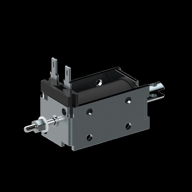
Sie können auch lesen