Einbauanleitung Funke BSM-Adapter DN150 und DN200
←
→
Transkription von Seiteninhalten
Wenn Ihr Browser die Seite nicht korrekt rendert, bitte, lesen Sie den Inhalt der Seite unten
Einbauanleitung Funke BSM-Adapter
DN150 und DN200
Mit dem Funke BSM-Adapter kann ein, nach DIN EN 1610 dichter Übergang an
Steinzeug- und Betonmuffen (mit Dichtung) hergestellt werden.

                                            Der BSM-Adapter ist je Nennweite (DN150 oder DN200) in zwei Versionen
                                            lieferbar.
                                            In Tabelle 1 ist ersichtlich, welcher BSM-Adapter für welche Rohrmuffe
                                            geeignet ist.

                                            BSM mit einer Einlegedichtung TYP1 (1):

                                            ArtikelNr. DN150: BSM150ED1
                                            ArtikelNr. DN200: BSM200ED1

                                            Lieferumfang:
                                            • BSM-Adapter DN150
                                            • Einlegedichtung TYP1
                                            • Gleitmittel 60ml
                                    1       • Steckschlüssel Inbus 5mm
                                            • Einbauanleitung

                                            Als Universalausführung mit zwei Einlegedichtungen (2)

                                            ArtikelNr. DN150: BSM150UNI
                                            ArtikelNr. DN200: BSM200UNI

                                            Lieferumfang:
                                            • BSM-Adapter DN150
                                            • Einlegedichtung TYP1 (dünne Dichtung)
                                            • Einlegedichtung TYP2 (dicke Dichtung)
                                            • Gleitmittel 60ml
                                            • Steckschlüssel Inbus 5mm
                                            • Einbauanleitung

                                    2

                                            Benötigtes Werkzeug (3):
                                            (nicht im Lieferumfang enthalten)

                                            Drehmomentschlüssel 4Nm mit Aufsatz Inbus 5mm

                                            Je nach Muffenform evtl.:
                                            • Brechstange (min. 1m)
                                            • Kantholz z.B. 6x8cm oder ähnlich

                                    3

                                                                                                                     1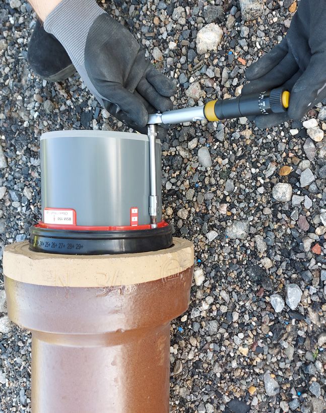
Zuordnung BSM zu Steinzeug oder Betonmuffe (Tabelle 1)
    Rohrmuffen an die angeschlossen werden kann          für Rohrmuffen DN150                   für Rohrmuffen DN200

 Muffe mit fest verbundener Dichtung                BSM150UNI          BSM150ED1         BSM200UNI            BSM200ED1
 Steinzeug DIN 295 Steckmuffe L
 Verbindungssystem F

 Muffe ohne Dichtung                                                                     BSM200UNI            BSM200ED1
 (Normallast)
 Steinzeug DIN 295 Steckmuffe K
 Verbindungssystem C

 Muffe ohne Dichtung                                                                     BSM200UNI
 (Hochlast)
 Steinzeug DIN 295 Steckmuffe K
 Verbindungssystem C

 sehr alte Muffe ohne Dichtung Stein-               BSM150UNI                           in Vorbereitung
 zeug DIN1230 (vor 1965)

 Betonrohr mit Dichtung                             BSM150UNI          BSM150ED1         BSM200UNI            BSM200ED1
                                                     ID-Muffe           ID-Muffe           ID-Muffe             ID-Muffe
                                                    186-220m             186-200            241-275              241-260
                                                    Muffentiefe        Muffentiefe     Muffentiefe 50mm     Muffentiefe 50mm
                                                      40mm                40mm

Einbauanleitung bezogen auf die unterschiedlichen Muffentypen

                                                  Muffe mit fest verbundener (integrierter) Dichtung (4)
                                                  Steinzeug DIN 295 Steckmuffe L Verbindungssystem F (seit ca. 1965)

                                                  Diese Muffenform kommt in den Nennweiten 150 und 200 vor.

                                              4

                                                  Gründlich die Dichtung säubern und auch den Bereich hinter der Dich-
                                                  tung am gesamten Umfang reinigen und jeglichen Schmutz und Steine
                                                  entfernen. (5)

                                                  Dann tasten und optisch prüfen ob die Muffe einen Riss hat.

                                                  Wenn ein Riss vorhanden ist, besteht die Gefahr, dass die Verbindung
                                                  auch mit dem BSM-Adapter nicht nach DINEN1610 dicht wird.
                                                  (Dann prüfen ob die Muffe abgeschnitten und eine VPC-Rohrkupplung
                                                  genutzt werden kann.)
                                              5

                                                  Die Einlegedichtung TYP1 (die dünnere Dichtung wenn der BSMUNI
                                                  eingesetzt wird) in die Muffe, hinter die Dichtung des Steinzeugrohres
                                                  einlegen.

                                                  Dazu die Einlegedichtung an einer Stelle doppelt legen und ca. in eine
                                                  Herzform bringen um den Durchmesser zu verkleinern. (6)

                                              6

                                                                                                                               2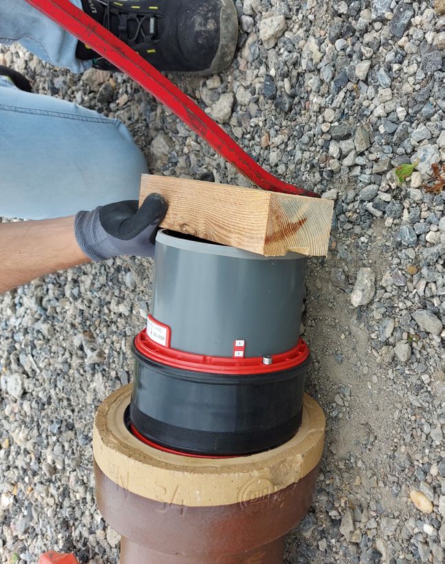
DN150: Die Einlegedichtung bis an den hinteren Anschlag des Muffenbe-
                             chers schieben und optisch und durch Tasten prüfen, ob sie umlaufend im
                             Muffenbecher anliegt. (7)

                             Die dünnen Lippen der Dichtungen zeigen zur Mitte des Rohres (7a)

                   7a
                         7

                             DN200: Die Dichtung wird so eingelegt, dass der dünnere Ansatz zur
                             Steinzeug-Dichtung zeigt. (8)

                         8

                             Ausreichend Gleitmittel umlaufend, nur auf die Steinzeug-Dichtung des
                             Steinzeug-Rohres, aufbringen. (9)
      Variante A                                           Variante B

                         9

                             Den BSM-Adapter genau in der Mitte vor die Muffe setzen. Mittig in
                             beide Richtungen, seitlich und in der Höhe. (10)
                             Wichtig ist, dass die Markierung „OBEN“ sich auch oben befindet damit
                             die beiden seitliche Schrauben gut erreichbar sind. (10a)

                   10a
10a
                        10

                             Jetzt den BSM-Adapter, ohne zu verkanten, bis zum Anschlag in die Muf-
                             fe drücken. (11)

                             Je nach Rohrhersteller des Steinzeugrohres können die Steckkräfte relativ
                             hoch sein.

                        11

                                                                                                         3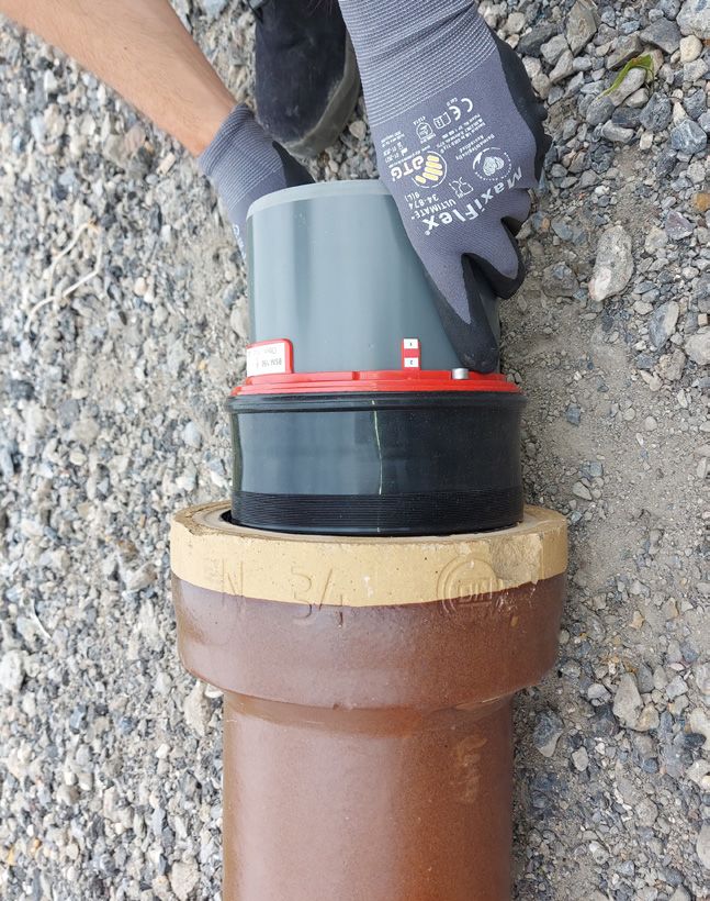
Dann ein geeignetes Kantholz (ca. 8x8cm) und eine Brechstange (min 1m
Länge) zur Hand nehmen und den BSM-Adapter mit Gefühl in Muffe pres-
sen. (12) NIEMALS mit einem Hammer auf den BSM-Adapter schlagen.
Der eingesteckte BSM-Adapter (13) hat an jeder Seite jeweils eine Schrau-
be und einen rot / weiß gestreiften Anzeiger (13a) mit Nummern 1;2;3;…
Jetzt mit dem beiliegenden 5mm-Sechskant-Schraubendreher die Schrau-
ben immer abwechselnd festdrehen.
WICHTIG: an jeder Seite immer abwechselnd je ca. 2 Umdrehungen dre-
12 hen.
Wichtig ist, dass der gestreifte Anzeiger an beiden Seiten immer ca. gleich
weit sichtbar ist.
Während des Schraubens mit der anderen Hand immer etwas Druck auf
den BSM-Adapter in die Richtung der Muffe ausüben.
13a Es darf kein Schlüssel mit T-Griff oder ein sonstiger Schlüssel genutzt wer-
den, mit dem ein deutlich höherer Drehmoment aufgebracht werden kann.
Wenn nur an einer Seite und mit zu hoher Kraft geschraubt wird, kann der
BSM-Adapter zerstört werden.
Abschließend mit einem Drehmomentschlüssel die beiden Schrauben mit
13 jeweils 4Nm festschrauben.
Einstellung des Drehmomentschlüssels: (14)
1. Stellrad (1) durch ziehen entriegeln
2. den roten Strich in der Anzeige genau auf 3Nm drehen und auf dem
Stellrad muss dann die 0 angezeigt werden.
3. das Stellrad dann um 1Nm weiterdrehen und verriegeln (drücken).
Jetzt ist das richtige Drehmoment von 4Nm eingestellt.
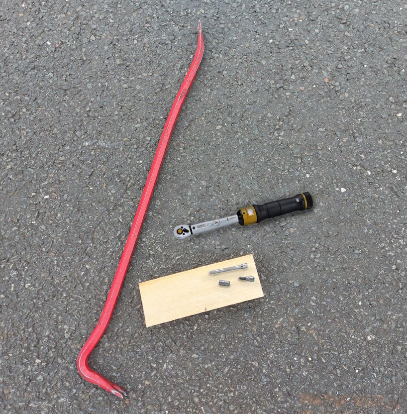
Jetzt den Drehmomentschlüssel ansetzen (15) und beide Schrauben ab-
wechselnd drehen bis der Schlüssel auslöst (vorne leicht abknickt). Sind die
1 Schrauben vor dem Ansetzen des Drehmomentschlüssels noch recht locker,
den Schlüssel nach einer Schraubenumdrehung immer wieder auf die
Gegenüberliegende Schraube setzen. Die Anzeiger (13a) müssen ungefähr
14 gleich weit sichtbar sein, wenn beide Schrauben angezogen sind. Hat der
Drehmometschlüssel an einer Schraube 1x ausgelöst ist diese ausreichend
fest.
Bevor der Drehmomentschlüssel wieder eingelagert wird, dass Stellrad wie-
der entriegeln und den Drehmomentschlüssel wieder auf 0Nm drehen.
Abschließend nochmals optisch kontrollieren ob der BSM Adapter gerade
in der Muffe sitzt und an der Innenseite fühlen ob der Muffenspalt umlau-
fend gleichmäßig verläuft.
Dann nochmal den festen Sitz des Adapters durch wackeln an dem Spit-
zende prüfen.
15 Eine gewisse Bewegung ist aufgrund des Gummimaterials der Dichtung
möglich. Grundsätzlich muss der BSM-Adapter aber fest in der Muffe
sitzen.
Nun entsprechend ein HS-Kanalrohr SN12 oder SN16 in Baulänge 0,5m
anschließen (Gelenkstück). Die weitere Verlegung und die Verfüllung des
Rohrgrabens muss entsprechend der DINEN1610 erfolgen.
Muffe ohne Dichtung
Steinzeug DIN 295 Steckmuffe K Verbindungssystem C (seit ca. 1965) (16)
Diese Muffenform ist ausschließlich in der Nennweite 200
zu finden, allerdings
als Normallast (N) Innendurchmesser Muffe 260mm
16 oder als Hochlast-Rohr (H) Innendurchmesser Muffe 275mm
4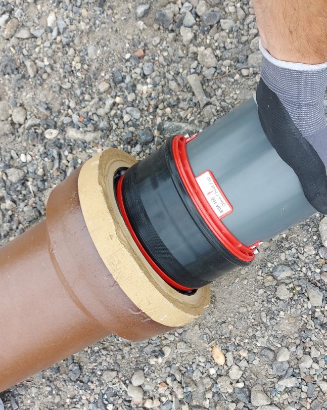
Ausführung Hochlast (H)
                                                                 Die Muffe wird gründlich gesäubert und auf Risse untersucht. Sind
                                                                 keine Risse vorhanden, wird die Einlegedichtung TYP2 eingelegt (die
                                                                 dickere der beiden Einlegedichtungen) und bis zum Anschlag in den
                                                                 Muffenbecher geschoben. (17) Ohne Gleitmittel den BSM-Adapter
                                                                 einstecken und die weitere Montage gemäß Punkt 10 bis 15 durchfüh-
                                                                 ren.

                                            17

                                                                 Ausführung Normallast (N)
                                                                 Die Muffe wird gründlich gesäubert und auf Risse untersucht. Sind
                                                                 keine Risse vorhanden wird die Einlegedichtung TYP1 zunächst in eine
                                                                 Schlaufe gelegt (siehe auch Bild 6) und in die Muffe eingelegt. (18)

                                            18

                                                                 Die Einlegedichtung so einlegen, dass der dünne Ansatz am Muffen-
                                                                 spiegel anliegt. (19) Ohne Gleitmittel den BSM-Adapter einstecken und
                                                                 die weitere Montage gemäß Punkt 10 und 15 duchführen.

                                            19

                                                                 Sehr alte Muffe ohne Dichtung Steinzeug DIN1230 (vor 1965)
                                             17                  Besonderheit: die inneren Oberflächen der Muffen sind Produktions-
                                                                 bedingt zum Teil sehr uneben. DN 150 Innendurchmesser ca. 220mm.
                    Variante B                                   (20)

                                                                 Sind die Unebenheiten sehr groß und verlaufen quer zu den umlau-
                                                                 fenden Rillen in den Muffen, kann es notwendig sein, die Muffe
                                                                 bauseits mit einer geeigneten Dichtmasse /Spachtelmasse vor zu be-
                                            20
                                                                 handeln. Zum Beispiel mit der Funke 2K-Dichtmasse.

                                                                 Die Muffe wird gründlich gesäubert und auf Risse untersucht. Sind
                                                                 keine Risse verhanden, wird die Einlegedichtung TYP2 eingelegt (die di-
                                                                 ckere der beiden Einlegedichtungen) und bis zum Anschlag in den Muf-
                                                                 fenbecher geschoben. Ohne Gleitmittel den BSM-Adapter einstecken
                                                                 und die weitere Montage gemäß Punkt 10 bis 15 durchführen. (21)
                                                                                                                                                                 Stand: 01-2023 - Technische Änderungen vorbehalten.

                                            21

                                                                 Betonrohrmuffen mit integrierter Dichtung
                                                                 Betonrohrmuffen DN 150 und 200 sind von vielen verschiedenen Her-
                                                                 stellern mit unterschiedlichsten, oft nicht genormten Formen produziert
                                                                 worden.
                                                                 Mögliche Maße an die angeschlossen werden kann, siehe Tabelle 1.
                                                                 Es sollte zunächst eine Einlegedichtung eingelegt werden, im Ausnah-
                                                                 mefall, wenn die alte Dichtung keinerlei Beschädigungen aufweist kann
                                                                 der BSM-Adapter auch ohne Einlegedichtung eingesetzt werden. Die
                                            22                   Montage des BSM-Adapters erfolgt gemäß Punkt 10 bis 15. (22)

Funke Kunststoffe GmbH • Siegenbeckstr. 15 • D-59071 Hamm-Uentrop • Tel.: +49 2388 3071-0 • Fax: +49 2388 3071-7550 • info@funkegruppe.de • www.funkegruppe.de
                                                                                                                                                                                           5
Installation instructions –
Funke BSM-Adapters DN 150 and DN 200
The Funke BSM-Adapter can be used to produce a tight transition to clay and concrete sockets (with
seal) in accordance with DIN EN 1610.

  Each of the BSM-Adapters (DN 150 or DN 200) are available in two versions.
  Table 1 shows which BSM-Adapter is suitable for which pipe socket.

  BSM with a TYPE 1 inlay seal (1):

  Product no. DN150: BSM150ED1
  Product no. DN200: BSM200ED1

  Scope of delivery:
  • BSM-Adapter DN 150
  • TYPE 1 inlay seal
  • Lubricant 60 ml
  • Box spanner (Allen) 5 mm
  • Installation instructions

  As universal version with two inlay seals (2)

  Product no. DN150: BSM150UNI
  Product no. DN200: BSM200UNI

  Scope of delivery:
  • BSM-Adapter DN 150
  • TYPE 1 inlay seal (thin seal)
  • TYPE 2 inlay seal (thick seal)
  • Lubricant 60 ml
  • Box spanner (Allen) 5 mm
  • Installation instructions

  Required tools (3):
  (not included in the scope of delivery)

  4 Nm torque wrench with 5 mm Allen attachment

  Depending on socket type, possibly:
  • Crowbar (min. 1 m)
  • Square timber, e.g., 6 x 8 cm or similar

                                                                                                     6
Classification – BSM to clay or concrete socket (Table 1)
         Pipe sockets that can be connected to              For DN 150 pipe sockets                for DN 200 pipe sockets

 Socket with fixed seal                                BSM150UNI           BSM150ED1         BSM200UNI             BSM200ED1
 Clay DIN 295 push-fit socket L
 Connection system F

 Socket without seal                                                                         BSM200UNI             BSM200ED1
 (normal load)
 Clay DIN 295 push-fit socket K
 Connection system C

 Socket without seal                                                                         BSM200UNI
 (high load)
 Clay DIN 295 push-fit socket K
 Connection system C

 Very old clay DIN 1230 socket with-                   BSM150UNI                            Available soon
 out seal (pre-1965)

 Concrete pipe with seal                               BSM150UNI           BSM150ED1         BSM150ED1             BSM200ED1
                                                        Socket ID           Socket ID         Socket ID             Socket ID
                                                        186-220m             186-200           186-200               241-260
                                                       Socket depth        Socket depth      Socket depth          Socket depth
                                                         40 mm                40 mm             40 mm                 50 mm

Installation instructions for different socket types

  Socket with fixed (integrated) seal (4)
  Clay DIN 295 push-fit socket L, connection system F (since approx. 1965) This socket type is available in nominal dia-
  meters 150 and 200.

  Thoroughly clean the seal as well as around the entire circumference of the area behind the seal and remove any dirt or
  stones. (5)

  Then, feel the socket with your hands and visually inspect it to see if it has a crack.

  If there is a crack, there is a risk that the connection will not be sealed in accordance with DIN EN 1610, even with the
  BSM-Adapter.
  (Then check if the socket can be cut off and a VPC pipe coupling can be used)

  Insert the TYPE 1 inlay seal (the thinner seal if the BSMUNI is used) into the socket, behind the clay pipe’s seal.

  To do this, pinch the inlay seal together on one side into almost a heart shape in order to reduce the diameter. (6)

  DN150: Push the inlay seal up to the rear stop of the length of engagement of socket and use your eyes and hands to
  check whether it fits closely around the entire circumference of the length of engagement of socket. (7)

  The thin lips of the seals point to the centre of the pipe (7a)

  DN200: Insert the seal so that the thinner area of the seal faces the clay seal. (8)

  Apply a sufficient amount of lubricant around only the seal of the clay pipe. (9)

                                                                                                                                  7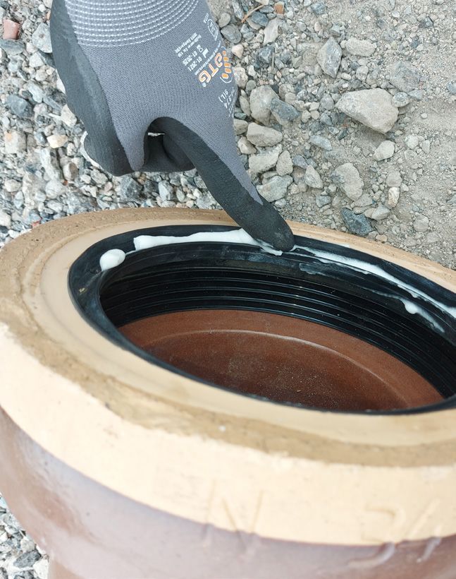
Place the BSM-Adapter exactly in the middle in front of the socket – centrally in both directions, laterally and vertically.
(10)
It is important that the marking ‘TOP’ is at the top so that the two screws on both sides are easily accessible. (10a)

Now press the BSM-Adapter, without tilting it, into the socket as far as it will go. (11)

The insertion forces can be relatively high depending on which company manufactured the clay pipe.

Gently, take a suitable piece of square timber (approx. 8 x 8 cm) and a crowbar (min. 1 m long) and press the BSM-Ad-
apter into the socket until you feel it stop. (12) NEVER hit the BSM-Adapter with a hammer.

The pushed-in BSM-Adapter (13) has a screw on each side and a red/white striped indicator (13a) showing the numbers
1, 2, 3...

Now, use the 5 mm hex screwdriver provided to tighten the screws, always alternating in the process.

IMPORTANT: Always tighten each side alternately after approx. two turns.
It is important that the striped indicator is always visible at approx. the same distance on both sides.

Always use one hand to apply a little pressure to the BSM-Adapter in the direction of the socket while using the other
one to tighten the screw.

Do not use a spanner with a T-handle or any other spanner that can be used to apply a significantly higher torque.

If only one side is screwed down, and with too much force, the BSM adapter could be destroyed.

Afterward, use a torque spanner to tighten each of the two screws to 4 Nm.
Adjusting the torque spanner: (14)
1.      Unlock the setting wheel (1) by pulling on it.
2.      Turn the red line in the display to exactly 3 Nm; the setting wheel must then show 0.
3.      Then, turn the setting wheel by an additional 1 Nm and lock it in place (press). The correct torque of 4 Nm is
        now set.

Now, use the torque spanner (15) and turn both screws alternately until the spanner releases (slightly bends at the front).
If the screws are still quite loose before using the torque spanner, always use the spanner on the opposite screw after one
screw turn. The indicators (13a) must be visible at approximately the same distance when both screws are tightened. The
screw is sufficiently tight once the torque spanner stops tightening one time.

Before putting away the torque spanner, unlock the setting wheel again and set the torque spanner back to 0 Nm.

Afterward, do another visual check to determine whether the BSM-Adapter is seated evenly in the socket and feel inside
whether the socket gap runs evenly the whole way around.
Then, check again to see if the adapter is firmly seated by wiggling the spigot end.

Some movement is possible due to the seal’s rubber material. However, in principle, the BSM-Adapter must be firmly
seated in the socket.
Now, connect a SN12 or SN16 HS sewer pipe with an installation length of 0.5 m accordingly (joint). Further work laying
and backfilling of the pipe trench must be carried out in accordance with DIN EN 1610.

                                                                                                                               8
Socket without seal
         Clay DIN 295 push-fit socket K, connection system C (since approx. 1965) (16)

         This socket type is found exclusively in DN 200, though
         the normal-load (N) version has an inner socket diameter of 260 mm
         and the high-load pipe (H) has an inner socket diameter of 275 mm.

         High-load version (H)
         Thoroughly clean the socket and inspect it for cracks. If there are no cracks, insert the TYPE 2 inlay seal (the thicker of
         the two inlay seals) and push it into the length of engagement of socket as far as it will go. (17) Insert the BSM-Adapter
         without lubricant and carry out further assembly according to points 10–15.

         Normal-load version (N)
         Thoroughly clean the socket and inspect it for cracks. If there are no cracks, first, place the TYPE 1 inlay seal in a loop
         (see also picture 6) and insert it into the socket. (18)

         Insert the inlay seal so that the thin area of the seal is in contact with the flat wall area within socket. (19) Insert the
         BSM-Adapter without lubricant and carry out further assembly according to points 10 and 15.

         Very old DIN 1230 clay socket without seal (pre-1965) Special characteristic: the socket’s inner surfaces are very
         uneven to some extent due to manufacturing processes. DN 150 internal diameter approx. 220 mm. (20)

         If the unevenness is extremely noticeable and runs at right angles to the surrounding grooves in the sockets, it may
         be necessary to pre-treat the socket on site using a suitable sealant/filling material – for example, with the Funke 2-C
         sealant.

         Thoroughly clean the socket and inspect it for cracks. If there are no cracks, insert the TYPE 2 inlay seal (the thicker
         of the two inlay seals) and push it into the length of engagement of socket as far as it will go. Insert the BSM-Adapter
         without lubricant and carry out further assembly according to points 10–15. (21)

         Concrete pipe socket with integrated seal
         DN 150 and 200 concrete pipe sockets have been manufactured by a wide range of different manufacturers in a wide
         variety of often non-standardised shapes. (22)
         See Table 1 for possible dimensions that can be connected to. An inlay seal should be inserted first.
         As an exception, the BSM-Adapter can also be used without an inlay seal if the old seal is not damaged in any way. The
         BSM-Adapter is assembled according to points 10–15.

                                                                                                                                                                  Last updated: 01/2023 – We reserve the right to make

Funke Kunststoffe GmbH • Siegenbeckstr. 15 • D-59071 Hamm-Uentrop • Tel.: +49 2388 3071-0 • Fax: +49 2388 3071-7550 • info@funkegruppe.de • www.funkegruppe.com
                                                                                                                                                                                              9
Instructions de montage adaptateur
Funke BSM DN150 et DN200
L‘adaptateur Funke BSM permet de réaliser un raccordement étanche selon la norme DIN EN 1610 sur les tulipes
en grès et en béton (avec joint).

   L‘adaptateur BSM est disponible en deux versions selon le
   diamètre nominal (DN150 ou DN200).
   Le tableau 1 indique quel adaptateur BSM est adapté à quelle
   tulipe.

   BSM avec un joint d‘insertion TYPE 1 (1) :

   N° de réf. DN150 : BSM150ED1
   N° de réf. DN200 : BSM200ED1

   Contenu de la livraison:
   • Adaptateur BSM DN150
   • Joint d‘insertion TYPE 1
   • Lubrifiant 60 ml
   • Clé Allen à douille 5 mm
   • Instructions de montage

   En version universelle avec deux joints d‘insertion (2)

   N° de référence DN150 : BSM150UNI
   N° de réf. DN200 : BSM200UNI

   Contenu de la livraison:
   • Adaptateur BSM DN150
   • Joint d‘insertion TYPE 1 (joint fin)
   • Joint d‘insertion TYPE 2 (joint épais)
   • Lubrifiant 60 ml
   • Clé Allen à douille 5 mm
   • Instructions de montage

   Outillage nécessaire (3):
   (non fournis à la livraison)

   Clé dynamométrique 4 Nm avec douille Allen 5 mm

   Selon la forme du tulipe, éventuellement :
   • Pied-de-biche (min. 1 m)
   • Pièce de bois équarri, par ex. 6x8 cm ou similaire

                                                                                                               10
Affectation du BSM au grès ou au béton (tableau 1)
Tulipe avec lesquelles un raccordement est possible pour tulipes DN150 pour tulipes DN200
Tulipe avec joint d‘etancheite fixe BSM150UNI BSM150ED1 BSM200UNI BSM200ED1
grès DIN 295 tulipe L
système de raccord F
Tulipe sans joint d’étanchéité BSM200UNI BSM200ED1
(Charge normale)
grès DIN 295 tulipe K
système de raccord C
Tulipe sans joint d’étanchéité BSM200UNI
(Charge élevée)
grès DIN 295 tulipe K
système de raccord C
Très ancien tulipe sans joint grès BSM150UNI en cours de
DIN1230 (avant 1965) préparation
Tube en béton avec joint d’étanchéité BSM150UNI BSM150ED1 BSM200UNI BSM200ED1
Tulipe ID Tulipe ID Tulipe ID Tulipe ID
186-220m 186-200 241-275 241-260
Profondeur de la Profondeur de la Profondeur de la Profondeur de la
tulipe tulipe tulipe tulipe
40 mm 40 mm 50 mm 50 mm
Instructions de montage en fonction des differents types de tulipes
TULIPE AVEC JOINT D‘ETANCHEITE FIXE (INTEGRE) (4)
Grès DIN 295 tulipe L système d‘assemblage F (depuis env. 1965)
Cette forme de tulipe existe dans les diamètres nominaux 150 et 200.
Nettoyer soigneusement le joint et la zone située derrière le joint sur toute sa circonférence et enlever toutes les saletés et
les pierres. (5)
Ensuite, palper et vérifier visuellement si le tulipe est fissuré.
Si une fissure est présente, il existe un risque que le raccordement ne soit pas étanche selon la norme DIN EN1610, même
avec l‘adaptateur BSM. (Vérifier ensuite si la tulipe peut être coupé et si un tulipe VPC peut être utilisé).
Placer le joint d‘insertion TYPE 1 (le joint le plus fin si le BSMUNI est utilisé) dans la tulipe, derrière le joint du tube en grès.
Pour cela, doubler le joint d‘insertion à un endroit et lui donner approximativement la forme d‘un cœur pour réduire son
diamètre. (6)
DN150 : Pousser le joint d‘insertion jusqu‘à la butée arrière du logement de la tulipe et vérifier visuellement et par tâtonne-
ment qu‘il est bien en place sur tout le pourtour du logement de la tulipe. (7)
Les lèvres fines des joints sont orientées vers le milieu du tube. (7a)
DN200 : Le joint est inséré de manière à ce que l‘embout le plus fin soit dirigé vers le joint en grès. (8)
Appliquer une quantité suffisante de lubrifiant sur tout le pourtour, uniquement sur le joint d‘etancheite en grès du tuyau
en grès. (9)
11Placer l‘adaptateur BSM exactement au milieu devant le tulipe. Au centre dans les deux sens, sur les côtés et en hauteur.
(10)
Il est important que le repère « HAUT » se trouve également en haut afin que les deux vis latérales soient facilement
accessibles. (10a)
Enfoncer maintenant l‘adaptateur BSM dans la tulipe jusqu‘à la butée, sans l‘incliner. (11)
Selon le fabricant du tuyau en grès, les forces d‘emboîtement peuvent être relativement élevées.
Prendre ensuite une pièce de bois équarri appropriée (env. 8x8 cm) et un pied de biche (min. 1m de long) et presser
l‘adaptateur BSM dans la tulipe avec précaution. (12) Ne Jemais frapper l‘adaptateur BSM avec un marteau.
L‘adaptateur BSM (13) a une vis de chaque côté et un indicateur à rayures rouges et blanches (13a) avec les numéros 1,
2, 3,...
À l‘aide du tournevis à tête hexagonale de 5 mm fourni, visser maintenant les vis, toujours en alternance.
IMPORTANT: de chaque côté, en alternance, tourner d‘environ 2 tours.
Il est important que l‘indicateur rayé soit toujours visible à peu près à la même distance des deux côtés.
Pendant le vissage, exercer toujours avec l‘autre main une certaine pression sur l‘adaptateur BSM dans la direction de la
tulipe.
Il est interdit d‘utiliser une clé à poignée en T ou toute autre clé permettant d‘appliquer un couple nettement plus élevé.
Si l‘on ne visse que d‘un seul côté et avec une force trop importante, l‘adaptateur BSM peut être détérioré.
Enfin, à l‘aide d‘une clé dynamométrique, serrer les deux vis à 4 Nm chacune.
Réglage de la clé dynamométrique: (14)
1. Déverrouiller la molette de réglage (1) en la tirant.
2. Tourner le trait rouge de l‘affichage exactement sur 3 Nm et le 0 doit alors s‘afficher sur la molette de réglage.
3. Tourner ensuite la molette de réglage de 1 Nm et la verrouiller (appuyer). Le couple correct de 4 Nm est maintenant
réglé.
Placer maintenant la clé dynamométrique (15) et tourner les deux vis en alternance jusqu‘à ce que la clé se déclenche (elle
se plie légèrement à l‘avant). Si les vis sont encore assez lâches avant d‘appliquer la clé dynamométrique, toujours replacer
la clé sur la vis opposée après un tour de vis. Les indicateurs (13a) doivent être visibles à peu près à la même distance lors-
que les deux vis sont serrées. Si la clé dynamométrique s‘est déclenchée 1x sur une vis, celle-ci est suffisamment serrée.
Avant de ranger la clé dynamométrique, déverrouiller à nouveau la molette de réglage et tourner la clé dynamométrique
sur 0 Nm.
Enfin, contrôler à nouveau visuellement si l‘adaptateur BSM est bien placé dans la tulipe et palper l‘intérieur pour vérifier
que l‘espace entre les tulipes est régulier sur tout le pourtour.
Vérifier ensuite à nouveau que l‘adaptateur est bien fixé en secouant l‘extrémité de l‘embout mâle.
Un certain mouvement est possible en raison du matériau en caoutchouc du joint. Mais en principe, l‘adaptateur BSM doit
être bien fixé dans le tulipe.
Raccorder ensuite un tube HSK SN12 ou SN16 d‘une longueur de 0,5 m (pièce de raccord). La suite de la pose et le rem-
blayage de la tranchée doivent être effectués conformément à la norme DIN EN 1610.
12Tulipe sans joint d‘étanchéité
Grès DIN 295 tulipe K système d‘assemblage C (depuis env. 1965) (16)
Cette forme de tulipe se trouve exclusivement dans le diamètre nominal de 200,
acomme charge normale (N), diamètre intérieur du tulipe 260 mm
ou en tant que tube haute charge (H), diamètre intérieur du tulipe 275 mm.
Version Haute charge (H)
La tulipe est soigneusement nettoyée et inspectée pour détecter d‘éventuelles fissures. Si aucune fissure n‘est présente,
insérer le joint d‘insertion TYPE 2 (le plus épais des deux joints d‘insertion) et le pousser jusqu‘à la butée dans le loge-
ment de la tulipe. (17) Sans lubrifiant, insérer l‘adaptateur BSM et effectuer la suite du montage selon les points 10 à
15.
Versiom charge Normale (N)
La tulipe est soigneusement nettoyée et inspectée pour détecter d‘éventuelles fissures. Si aucune fissure n‘est présente,
le joint d‘insertion TYPE 1 est d‘abord placé dans une boucle (voir aussi la figure 6) et inséré dans la tulipe. (18)
Mettre en place le joint d‘insertion de manière à ce que l‘embout fin soit en contact avec la tulipe. (19) Sans lubrifiant,
insérer l‘adaptateur BSM et effectuer la suite du montage selon les points 10 et 15.
Très ancienne tulipe sans joint grès DIN1230 (avant 1965) Particularité : les surfaces intérieures des tulipes sont en
partie très irrégulières en raison de la production. DN 150 Diamètre intérieur env. 220 mm. (20)
Si les irrégularités sont très importantes et s‘étendent transversalement aux rainures périphériques dans les tulipes, il
peut s‘avérer nécessaire de traiter préalablement le tulipe sur le chantier avec un mastic/enduit d‘étanchéité approprié.
Par exemple avec le mastic d‘étanchéité bicomposant Funke.
La tulipe est soigneusement nettoyée et inspectée pour détecter d‘éventuelles fissures. Si aucune fissure n‘est présente,
insérer le joint d‘insertion TYPE 2 (le plus épais des deux joints d‘insertion) et le pousser jusqu‘à la butée dans le loge-
ment de la tulipe. Sans lubrifiant, insérer l‘adaptateur BSM et effectuer la suite du montage selon les points 10 à 15.
(21)
Tulipes pour tubes en béton avec joint intégré
Les tulipes pour tubes en béton DN 150 et 200 ont été produites par de nombreux fabricants différents, avec des
formes très variées, souvent non conformes aux normes. (22)
Dimensions auxquelles il est possible de se raccorder, voir tableau 1. Il convient tout d‘abord d‘insérer un joint
d‘insertion.
Dans des cas exceptionnels, lorsque l‘ancien joint ne présente aucun dommage, l‘adaptateur BSM peut également être
utilisé sans joint d‘insertion. Le montage de l‘adaptateur BSM s‘effectue conformément aux points 10 à 15.
Version : 01-2023 - Sous réserve de modifications
Funke Kunststoffe GmbH • Siegenbeckstr. 15 • D-59071 Hamm-Uentrop • Tél.: 04 78 30 11 88 • Fax: 04 78 30 43 77 • funkefrance@funkegruppe.de • www.funkefrance.fr
13Instrukcja Funke BSM-Adapter DN150 i DN200
Adapter Funke BSM umożliwia zgodnie z normą DIN EN 1610 wykonanie szczelnego przejścia z kielicha rury
kamionkowej i betonową ( z uszczelką)
Adapter BSM jest dostępny w dwóch wersjach w zależności od rozmiaru nominalnego (DN150 lub DN200).
Tabela 1 pokazuje, który adapter BSM jest odpowiedni dla danego połączenia z mufą.
BSM z uszczelką TYP1 (1): W wersji uniwersalnej z dwoma uszczelkami wewnętrznymi (2)
Artykuł Nr. DN150:BSM150ED1 Artykuł Nr. DN150:BSM150UNI
Artykuł Nr. DN200:BSM200ED1 Artykuł Nr. DN200:BSM200UNI
Zakres dostawy: Zakres dostawy:
• Adapter-BSM DN150 • Adapter-BSM DN150
• Uszczelka TYP1 • Uszczelka TYP1 (cienka uszczelka)
• Środek poślizgowy 60ml • Uszczelka TYP1 (gruba uszczelka)
• Klucz imbusowy 5mm • Środek poślizgowy 60ml
• Instrukcja • Klucz imbusowy 5mm
• Instrukcja
Wymagane narzędzia (3):
(nie wchodzi w zakres dostawy)
Klucz dynamometryczny 4Nm z nasadką Imbus
5mm W zależności od kształtu mufki ewent.:
• Łom (min. 1m)
• Kantówka np. 6x8cm lub podobne
Przyporządkowanie BSM do kielicha rury kamionkowej lub kielicha rury betonowej (Tabela 1)
Kielichy rur do których można wykonać połączenie Do kielichów DN150 Do kielichów DN200
Kielich z trwale połączoną uszczelką BSM150UNI BSM150ED1 BSM200UNI BSM200ED1
Kamionka DIN 295 Kielich L
System łączenia F
Kielich bez uszczelki BSM200UNI BSM200ED1
(klasa obciążenia normatywna)
Kamionka DIN 295 Kielich K
System łączenia C
Kielich bez uszczelki BSM200UNI
(klasa obciążenia ponadnormatywna)
Kamionka DIN 295 Kielich K
System łączenia C
Bardzo stara rura kamionkowa bez BSM150UNI W przygotowaniu
uszczelki w kielichu DIN1230 (przed
1965)
Rura betonowa z uszczelką BSM150UNI BSM150ED1 BSM200UNI BSM200ED1
ID-Mufa ID-Mufa ID-Mufa ID-Muffa
186-220m 186-200 241-275 241-260
Głębokość mufy Głębokość mufy Głębokość mufy Głębokość mufy
40mm 40mm 50mm 50mm
14Instrukcja dotycząca różnych typów kielichów
Kielich z trwale połączoną (zintegrowaną) uszczelką (4)
Kamionka DIN 295 Kielich L System łączenia F (od ok. 1965).
Ten kształt kielicha występuje w rozmiarach nominalnych 150 i 200.
Dokładnie oczyścić uszczelkę oraz obszar za uszczelką na całym obwodzie i usunąć wszelkie zabrudzenia i kamienie. (5)
Następnie dotknij i sprawdź wizualnie, czy kielich ma pęknięcie.
W przypadku pęknięcia istnieje ryzyko, że połączenie nie zostanie szczelne nawet z adapterem BSM zgodnie z DIN EN 1610.
(następnie sprawdzić, czy można odciąć kielich i użyć złącze VPC)
Włożyć uszczelkę TYP1 (cieńszą uszczelkę w przypadku zastosowania BSMUNI) do mufy za uszczelką rury kamionkowej.
W tym celu należy dwukrotnie umieścić uszczelkę w jednym miejscu i uformować ją w kształcie serca, aby zmniejszyć
średnicę. (6)
DN150: Przesuń uszczelkę do tylnej części uchwytu kielicha i sprawdź wizualnie i fizycznie, czy jest ona osadzona w
kołnierzu kielicha. (7)
Cienkie wargi uszczelek wskazują środek rury. (7a)
DN200: Uszczelka jest wkładana w taki sposób, że jej cieńsza część skierowana jest w kierunku uszczelki kamionkowej. (8)
Środek poślizgowy nakładać tylko na uszczelkę kamionkową rury kamionkowej. (9)
Adapter BSM umieścić dokładnie pośrodku mufy. Zarówno z boku i na wysokości. (10)
Ważne jest, aby oznaczenie „GÓRA” znajdowało się również na górze, aby dwie boczne śruby były łatwo dostępne. (10a)
Teraz wciśnij adapter BSM bez obracania do kielicha. (11)
W zależności od producenta rur kamionkowych, należy użyć odpowiedniej siły do montażu adaptera.
Weź do ręki odpowiednią kantówkę drewnianą(ok. 8x8cm) i łom (min 1m długości) i z wyczuciem wciśnij adapter BSM do
kielicha. (12) NIGDY nie uderzaj młotkiem w adapter BSM.
Podłączony adapter BSM (13) ma po obu stronach śrubę i czerwono biały wskaźnik (13a) z numerami 1;2;3;…
Teraz za pomocą dołączonego śrubokręta sześciokątnego (imbus) 5mm dokręcaj śruby – zawsze na przemian.
WAŻNE: z każdej strony dokręcaj na przemian po około 2 obroty.
Ważne jest, aby wskaźnik po obu stronach był w tej samej pozycji.
Podczas wkręcania zawsze wywieraj drugą ręką niewielki nacisk na adapter BSM w kierunku kielicha.
Nie używać klucza z uchwytem typu T lub innego klucza, który może spowodować znacznie wyższy moment obrotowy.
15Dokręcenie tylko z jednej strony i użycie zbyt dużej siły może spowodować zniszczenie adaptera BSM.
Na koniec dokręcić dwie śruby wartością 4 Nm za pomocą klucza dynamometrycznego.
Ustawienie klucza dynamometrycznego: (14)
1. pokrętło górne (1) odblokować przez pociągnięcie .
2. obróć czerwona kreskę na wyświetlaczu z dokładnością do 3Nm, a następnie na kole sterującym musi pojawić się 0.
3. przekręć pokrętło sterujące tak, aby pojawiło się 0.
4. Następnie przekręć pokrętło sterujące o 1Nm i zablokuj (naciśnij). Teraz ustawiony jest prawidłowy moment ob-
rotowy 4Nm.
Włóż klucz dynamometryczny (15) i obracaj na przemian obie śruby do momentu uruchomienia klucza (słyszalne
kliknięcie). Jeśli śruby są nadal dość luźne przed użyciem klucza dynamometrycznego, śruby ponownie na przemian
dokręcić. Wskaźniki (13a) muszą być mniej więcej jednakowo widoczne po dokręceniu obu śrub. Jeśli klucz dynamo-
metryczny był przekręcony po 1 razie na śrubę po osiągnięciu zadanej wartości oznacza to, że śruba jest wystarczająco
mocno dokręcona.
Przed ponownym użyciem klucza dynamometrycznego należy zwolnić blokadę i nastawić klucz dynamometryczny na
wartość 0 Nm.
Na koniec ponownie sprawdzić optycznie, czy adapter BSM znajduje się bezpośrednio w kielichu i należy również
sprawdzić po wewnętrznej stronie, czy szczelina wokół kielicha jest równa na całym obwodzie.
Następnie ponownie sprawdzić czy adapter jest mocno osadzony próbując poruszać wystającym bosym końcem rury.
Minimalny ruch jest możliwy ze względu na gumowy materiał uszczelki. Zasadniczo jednak adapter BSM musi być mocno
osadzony w kielichu.
Teraz odpowiednio podłączyć rurę kanalizacyjną HS SN12 lub SN16 o długości 0,5m (króciec). Dalsze układanie i zasypy-
wanie wykopu rurowego musi odbywać się zgodnie z normą DINEN1610.
Kielich bez uszczelki
Kamionka DIN 295 Kielich K System łączenia C (od ok. 1965) (16)
Taki kształt kielicha występuje tylko w średnicy nominalnej 200, ale jako normatywne obciążenie (N) o średnicy
wewnętrznej kielicha 260mm lub jako rura ponadnormatywna o obciążeniu (H) i średnicy wewnętrznej kielicha 275mm.
Montaż w rurach ponadnormatywnych (H)
Kielich dokładnie oczyścić i sprawdzić pod kątem pęknięć. Jeśli nie ma pęknięć włożyć uszczelkę TYP2 (najgrubszą z
dwóch uszczelek) i umieścić ją na końcu kielicha (17).
Adapter BSM włożyć bez użycia środka poślizgowego i kontynuować montaż zgodnie z punktami od 10-15.
Montaż w rurach normatywnych (N)
Kielich dokładnie oczyścić i sprawdzić pod kątem pęknięć. Jeśli nie ma pęknięć wywinąć uszczelkę TYP1 w sposób podob-
ny jak(patrz rys. 6), a następnie włożyć do kielicha (18)
Włóż uszczelkę w taki sposób, aby cienka końcówka znajdowała się na końcu kielicha (19).
Adapter BSM włożyć bez użycia środka poślizgowego i kontynuować montaż zgodnie z punktami od 10-15.
Bardzo stary kielich bez uszczelki, kamionka DIN1230 (przed 1965) Cechy szczególne: wewnętrzne powierzchnie
kielicha są częściowo bardzo nierówne ze względu na produkcję. DN 150 Średnica wewnętrzna ok. 220mm. (20)
Jeśli nierówności są bardzo duże i przebiegają poprzecznie do okrągłych rowków w kielichach, może być konieczne użycie
odpowiedniej masy uszczelniającej/ szpachlowej. Na przykład masy uszczelniającej 2K Funke.
Stan na: 01-2023 - Zmiany techniczne zastrzeżone.
Kielich dokładnie oczyścić i sprawdzić pod kątem pęknięć. Jeśli nie ma pęknięć włożyć uszczelkę TYP2 (najgrubszą z
dwóch uszczelek) i umieścić ją na końcu kielicha.
Adapter BSM włożyć bez użycia środka poślizgowego i kontynuować montaż zgodnie z punktami od 10-15. (21)
Kielich rury betonowej ze zintegrowaną uszczelką.
Kielichy rur betonowych DN 150 i 200 są produkowane przez wielu różnych producentów o najróżniejszych, często nie-
standardowych kształtach. (22)
Możliwe wymiary, do których można podłączyć, patrz tabela 1. Najpierw należy włożyć uszczelkę, a w wyjątkowych
przypadkach, gdy stara uszczelka nie jest uszkodzona, adapter BSM może być stosowany nawet bez uszczelki. Montaż
adaptera BSM odbywa się zgodnie z pkt 10–15.
Funke Kunststoffe GmbH • Siegenbeckstr. 15 • D-59071 Hamm-Uentrop • Tel.: +49 2388 3071-0 • Fax: +49 2388 3071-7550 • info@funkegruppe.de • www.funkegruppe.pl
16Sie können auch lesen