FlexAct UD Central Operating Module (COM) - 85032-540-80 Vers. 07
←
→
Transkription von Seiteninhalten
Wenn Ihr Browser die Seite nicht korrekt rendert, bitte, lesen Sie den Inhalt der Seite unten
Operating Manual | Betriebshandbuch

  FlexAct® UD Central Operating Module (COM)

                                   85032-540-80   Vers. 07 | 2014

85032-540-80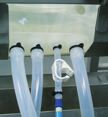
Contents | Inhalt
Legal Notices | Impressum...................................................................... Page 2
English........................................................................................................... Page 3
Deutsch......................................................................................................... Seite 41

Fig. Front cover: FlexAct® UD COM | Abb. Titelseite: FlexAct® UD COM

Sartorius Stedim Biotech GmbH

Technical Documentation | Technische Dokumentation
August-Spindler-Strasse 11

D-37079 Goettingen
Germany | Deutschland
Internet: www.sartorius-stedim.com
E-mail: tech.pubs@sartorius-stedim.com

Printed in Germany on chlorine-free paper.
If you require mandatory information regarding specific properties of your FlexAct® UD
COM that goes beyond that which is described here, please contact us.

No part of this publication may be reprinted, reproduced or translated in any
form or by any means without the prior written permission of
Sartorius Stedim Biotech GmbH.
FlexAct® is a registered trademark of Sartorius Stedim Biotech GmbH

Gedruckt in Deutschland auf chlorfreiem Papier
Wenn Sie verbindliche Informationen zu bestimmten Eigenschaften Ihres
FlexAct® UD COM benötigen, welche über die hier beschriebenen hinausgehen,
bitten wir um Ihre Anfrage.

Nachdruck, Übersetzung und Vervielfältigung in jeglicher Form, auch auszugsweise,
bedürfen der schriftlichen Genehmigung der Sartorius Stedim Biotech GmbH.
FlexAct® ist eingetragenes Warenzeichen der Sartorius Stedim Biotech GmbH
Contents
       Introduction
I.     Introduction
II.    Abbreviations
III.   Definitions
IV.    Operating Instructions | Intended Use
V.     Document Structure
VI.    Explanation of Symbols
VII.   Safety Instructions

1. Setup and Equipment............................................................................................................              9
   1.1 System Structure............................................................................................................             9
   1.2 Setup and Structure of FlexAct® UD COM..............................................................                                     9
   1.3	Control Unit with Measurement and Control System........................................                                               10

2. Getting Started | Initial Installation...............................................................................                       11
   2.1 General..............................................................................................................................   11
   2.2 Transportation.................................................................................................................         11
   2.3 Checks Prior to Setup and Connection....................................................................                                11
   2.4	Requirements Relating to Connections |
        Energy Supply Lines on the Laboratory and Production Sides.........................                                                    12
   2.5 Setup and Connection..................................................................................................                  12
   2.6	Connections and Energy Supply Lines (Default Values).....................................                                              15
   2.7 Installation of the Pressure Sensor...........................................................................                          15
   2.8 Disposal Facilities...........................................................................................................          17
   2.9 Installing the Pump.......................................................................................................              17
   2.10 Installing the Filter Holder..........................................................................................                 19
   2.11 Installing the Scale........................................................................................................           19
   2.12 Concluding the Installation Activities.....................................................................                            20

3. Process Installation | Process Start.................................................................................                       21
   3.1 General..............................................................................................................................   21
   3.2 Safety Instructions........................................................................................................             21
   3.3 Installing the Magnetic Mixer Tank (Signal Cable Guide).....................................                                            21
   3.4 Setting up of the mixing system...............................................................................                          22
   3.5	Completing the Process Setup Steps........................................................................                             27
   3.6 Valve Matrix.....................................................................................................................       28

4. Running the Process with FlexAct® UD COM...............................................................                                     29
   4.1 General Principles of Operation................................................................................                         29
   4.2 Process Start....................................................................................................................       29
   4.3 Start Screen | Process Control...................................................................................                       29
       “Main” Main Function..................................................................................................                  29
       “Trend” Main Function.................................................................................................                  29
       “Settings” System Configuration..............................................................................                           29
       Calibrating the Sensors................................................................................................                 29
   4.4 Predefined Phases and Process Example.................................................................                                  30
   4.5 Other Functions .............................................................................................................           39

5. Ending the Process.................................................................................................................         40
   5.1 End of Process.................................................................................................................         40
   5.2 Concluding Processes, Cleaning and Maintenance...............................................                                           40
        Optional Features, Special Accessories....................................................................                             40
        General Notes..................................................................................................................        40

                                                                                                                     Contents                   3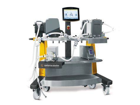
Introduction Introduction
FlexAct® UD COM is a work platform that links together a variety of biomanufactur
I. Introduction
ing tasks. A microcomputer and touch-screen driven operation enable the user to
document and display process-relevant data.
This document describes different models and equipment of FlexAct® UD COM that
were available at the time of its creation. The equipment supplied with a device does
not necessarily cover every possible type of equipment; some may differ from the
description while others may contain additional equipment. The descriptions for the
fittings can differ from the ones in the related P&I diagram and the equipment list
because these documents are each adapted to the customer’s specific requirements.
Documentation on customer-specific designs and equipment can be separately
supplied or are available on request.
Sartorius Stedim Biotech GmbH
Customer Service
August-Spindler-Strasse 11
37079 Goettingen, Germany
Phone +49.551.308.3318
Fax +49.551.308.3755
www.sartorius-stedim.com
II. Abbreviations BI Basic Issue
BP Buffer Preparation
COM Central Operating Module
DCU FlexAct® Sartorius Stedim Measurement and Control System
l/L Liter
P&I Diagram Piping & Instrumentation Diagram
SSB Sartorius Stedim Biotech
VI Virus Inactivation
CDS Configurable Disposable Solution
MP Media Preparation
VR Virus Removal
CH Cell Harvest
UD Ultrafiltration Diafiltration
4 Introduction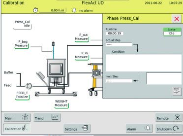
III. Definitions                      FlexAct® UD COM	FlexAct® UD COM ready-to-connect system with
                                                       – Trolley,
                                                       – Recirculation pump
                                                       – DCU microbox
                                                       – Touch-screen
                                                       – Feed pump
                                                       – Crossflow filter holder with handhydraulic pump
                                                       – Pump head supporting plate
                                                       – PT100 temperature sensor
                                                       and
                                                       – Pressure sensors

                                      Initial Installation | Description of all steps required to set up FlexAct® UD COM
                                      Getting Started	after its delivery or whenever its location is moved.
                                      	Once assembly | installation of attached parts and the pump
                                                             is completed, the steps for initial installation are concluded
                                                             by connecting FlexAct® UD COM to the power supply in the
                                                             laboratory or belonging to the process.

                                      Process Installation |       Description of all steps required to start a process.
                                      Process Start

                                      Process Capability	Time at which the actual process, Ultrafiltration |
                                                          Diafiltration, can be started. Process capability is reached
                                                          when the initial operations are set up to completion.

IV. Operating Instructions | 	 FlexAct® UD COM may only be used with equipment and under operating conditions
Intended Use	described in the present equipment documentation. FlexAct® UD COM is basically a
                               work platform.

                                      Users must be qualified to handle the system and the process-relevant media and be
                                      aware of the hazards potentially associated with the process. Some processes may
                                      require that FlexAct® or the workplace be equipped with additional safety features or
                                      that precautions be otherwise taken to protect personnel and working environment.
                                      This document does not go into further detail about such circumstances, legislation
                                      or regulations that may otherwise bind the operator. Safety and warning instructions
                                      given in this document only apply to the devices and supplement the rules and
                                      regulations the operator stipulates at the workplace for the respective process.

                                      © Sartorius Stedim Biotech GmbH. No guarantee is assumed for the information provided. Sartorius
                                      reserves the right to make technical changes to the equipment or changes to this document without any
                                      prior notice. No part of this document may be changed, or reproduced, nor is any other use permitted
                                      without obtaining prior written permission.

                                                                                                                     Introduction             5
V. Document Structure This document is structured according to the following outline:
Chapter Contents
Introduction Notes on this document, operating and safety instructions
1. Information about setup and equipment of FlexAct® UD COM
2. Delivery, setup and connection | Initial installation in the laboratory |
production process:
– Workplace requirements, required installation and energy supplies
– Steps to make the equipment operable
3. Process installation | Start of the process running on FlexAct® UD COM
(Ultrafiltration | Diafiltration):
– Installation of the Palletank for storage with Crossflow filter loop
– Installation of the Magnetic Mixer® Palletank with sensors
– Instating process capability
4. Running a process with FlexAct® UD COM:
– Starting the process
– Start screen
– Process control (t Operating instructions manual for DCU FlexAct®)
– Calibrating the sensors
5. Concluding the process with FlexAct® UD COM:
– End of process
– Deinstallation of Magnetic Mixer®, Palletank®, Recirculation –
BagLoop Assembly, Palletank® for storage
VI. Explanation of Symbols The “Warning” symbol and this formatting indicate hazards that can be
expected with a high probability and can lead to severe injuries.
The “Caution” symbol and this formatting indicate hazards that can occur and
can lead to severe injuries if the notes and instructions are not observed.
This warning indicates risks that can lead to material damage.
Instructions and notes labeled with this symbol indicate steps that must be
performed with particular care, or point to other especially important aspects
to be observed.
y The box indicates other important information.
1., 2., ... Numbered paragraphs indicate steps that should be performed consecutively in the
order listed.
t This symbol points to information referenced in another section.
6 IntroductionVII. Safety Instructions Organizational measures on the part of the operator:
y The operator must point out the hazards to which personnel and the working
environment may be subject during the process, must provide the suitable safety
equipment, and must publish the stipulated safety requirements.
y Only operating personnel qualified to run the process may be employed for
working with FlexAct® UD COM; they must be aware of potential hazards, and be
thoroughly familiar with the handling of all devices.
y Non-authorized persons must be prohibited from working on FlexAct® UD COM.
If hazards are associated with the process (e.g. due to process-relevant media),
the workplace must be labeled with suitable danger symbols, e.g. “BIOHAZARD”
and it should be possible to cordon it off or quarantine it if the circumstances
require.
y The workplace must be suitable for the process, e.g. resistant to acids, bases or
media and must be easy to clean, decontaminate and disinfect if contaminated.
y In general, operators must wear suitable personal protective equipment
(e.g. work clothes, gloves, safety goggles as well as a facemask if appropriate).
Workplace Setup
Workplace and supply connections in the laboratory | production facility must meet
the requirements stipulated in the equipment specifications. All intended equipment
must be complete and free of defects and flaws.
Risk of injury if energy supply lines are inadvertently activated
(e.g. power supply, water, gas inlet supplies).
Energy supply lines must be blocked or secured against inadvertent startup
whenever you:
Connect or disconnect laboratory connections or connections on the production
side.
Want to disassemble peripheral installations.
When transporting or moving FlexAct® UD COM, be fully aware that you are
moving equipment with an extremely high weight.
Ensure that all necessary measures are taken (e.g. warning information, barriers,
safety gear, etc.) to prevent any danger of crushing or roll-over, and thereby the
risk of injury to persons.
When assembling the PT 100 temperature sensor, make sure that the bag is
filled and not to damage the sensor channel when inserting the sensor.
Pierced or damaged sensor channels will make the bag unusable!
1. Ensure that all supply media on the laboratory or production sides , e.g. water,
supply voltage etc., match the specifications t “P&I Diagram”.
2. The workplace must be able to carry FlexAct® UD COM with all equipment and
the intended peripheral devices. Observe the weight and the space requirements
t „Setup and Connection“. Use suitable transportation aids when transporting
FlexAct® UD COM to the place of installation and | or changing its location.
3. Secure all laboratory connections | connections on the production side carefully.
Introduction 74. Use only the equipment provided or released for the device. Never make any
technical modifications, unless Sartorius Stedim Biotech GmbH has expressly
confirmed that this modification does not affect safe use.
5. Loosen | remove any transport locks.
6. Check all equipment carefully for damage. Use only flawless parts.
Getting Started
All equipment must be assembled carefully and safely.
1. Before every startup, check the assembly and connections of all equipment.
Safety equipment, e.g. the overpressure | safety valves must meet the
specifications and be installed.
2. Palletanks | bags, tubing, and fittings must be leak-tight.
Persons should only stand around the equipment for carrying out necessary
work. Barricade off the hazardous area and indicate this with signs!
If applicable, ensure that the respective minimum volumes as described in the
t “Operating Instructions Manual for Magnetic Mixer®” are not undershot.
Observe the operating limits and optimal settings for the process. Only operate
FlexAct® UD COM using the allowable energy supplies (power supply, water or gas
supplies).
BIOHAZARD, hazards caused by media.
When working with hazardous materials, observe the pertinent safety
regulations and laws!
1. Adjust the measurement and control system in strict accordance with the
allowable performance data for the respective equipment t “Operating
Instructions Manual for DCU FlexAct®”.
2. Perform in-process monitoring as to whether the process parameters are achieved
as expected. Take precautions to ensure that defects or disruptions cannot cause
any hazards or damage.
After placing the tubing in the pump, always make sure to press the STOP key on
the pump.
This resets the system and is indispensable for proper functioning of the pump.
After concluding the process, all affected components of FlexAct® UD COM should be
Safety at the End of the Process
disposed of, disinfected and cleaned in accordance with their use and as prescribed by
the respectively valid laws and regulations.
8 Overview of the Safety Instructions1. Setup and Equipment 1. Setup and Equipment
FlexAct® UD COM is controlled by a built-in DCU FlexAct® microcomputer. Operation
1.1 System Structure
is driven by a touch-screen securely mounted onto the trolley by a monitor arm.
Sensors, like those for pressure and temperature, are hooked to a sensor field on the
side. The “PT100 temperature sensor” included in the equipment supplied can also be
attached to the sensor field.
A Crossflow filter holder and a pump head supporting plate are standard components
of FlexAct® UD COM. Differently sized filters | capsules can be installed in the filter
holder. The pump head supporting plate is designed to stabilize the pump.
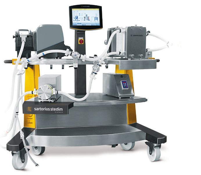
1.2 Setup and Structure of
FlexAct® UD COM
14 12 10 11 7 4 6 14 2 3 14 1 5 8 9 13
Fig. 1-1: Overview of FlexAct® UD COM
Equipment supplied with FlexAct® UD COM Accessory Devices Recommended Accessories (for Running the Process)
(1) COM (trolley) (8) Hydraulic Crossflow Filter holder
(2) Main switch | Emergency shutoff switch (9) Filter holder supporting plate
(3) Keypad | touch-screen (10) Drive Unit Magnetic Mixer®
(4) Recirculation Pump with Single-use pump chamber (11) Palletank® for Magnetic Mixer®
(5) Frequency converter (12) Holder for Venting Filterline
(6) Pump head supporting plate (13) Palletank® (“Storage“)
(7) Feed Pump (14) Pressure Sensor
System Setup 91.3 Control Unit with Measurement Hardware
and Control System The “DCU FlexAct®” measurement and control system is run by a microprocessor
specially designed and developed for the FlexAct® family. The unit is operated directly
on the touch-screen.
y Process controls as described in the t “Master Components List”.
y The t “Operating Instructions Manual for DCU FlexAct®” contains detailed
information about the hardware.
Peripheral Connections
FlexAct® UD COM can be ported to the following external devices:
y Scale
The t “Operating Instructions Manual for the Scale“ contains detailed
information about scales pre-configured for FlexAct® UD COM.
y Pressure Sensor (e. g. installed in the Flexel® bag for Magnetic Mixer®)
The t “Operating Instructions Manual for the Flexel® bag for Magnetic Mixer®“
contain safety instructions and detailed installation instructions.
y PT100 temperature sensor
The t “Operating Instructions Manual for the PT100 Temperature Sensor“
contains detailed information on the temperature sensor.
y External | alternative scale signal
If needed, please contact your local SSB service technician.
He would be happy to answer your questions!
y Ethernet port (multi-function)
Software updates,
Data transfer via MFCS
If needed, please contact your local SSB service technician.
He would be happy to answer your questions!
Software
y The t “Operating Instructions Manual for the DCU FlexAct®” contains detailed
information about the software.
10 System Setup2. Getting Started | Initial Installation 2. Getting Started | Initial Installation
2.1 General
Sartorius Stedim Biotech GmbH recommends that our authorized service technicians
carry out the initial installation FlexAct® UD COM at the operator’s workplace.
The following information summarizes the key aspects to be observed during the
setup. They also apply to the re-installation at the workplace after a change of
location or after temporary suspensions from use.
2.2 Transportation y Transportation equipment must be available that can sufficiently bear the load.
Transport routes and the potentially required elevator must be sufficiently
dimensioned and have the weight-bearing capacity needed to handle FlexAct®
UD COM and the transportation equipment without any hazards.
y Only use personnel qualified to transport FlexAct® UD COM. Prevent harm to
any uninvolved persons. Transport locks may not be removed until the system has
arrived at the place of installation.
Before you change the location of FlexAct® UD COM within the production facilities,
you must perform the following steps:
y Unplug all connections (refer to t “Chapter 5, Ending the Process”)
y Push the recirculation pump all the way back underneath the FlexAct® UD COM
working counter.
y De-install the pump head supporting plate
y Remove the Crossflow filter holder
2.3 Checks Prior to Setup Completeness of the supplies
and Connection
Check that the delivery is complete by comparing it against your order.
Check all components carefully for any damage.
y All required attached parts, tubing and|or cables that do not meet the
specifications of Sartorius Stedim Biotech GmbH may not be used.
y If damage that occurred during transport is noticed during startup, please notify
the hauler and have the damage documented for the record.
Report the transport damage, missing parts or malfunctions to your Sartorius
Stedim Systems GmbH representative.
Getting Started | Initial Installation 11
2.4 Requirements Relating to Danger of personal injury can arise if any power connections and supplies on the
Connections | Energy Supply laboratory or production sides are not correctly secured against unallowable
Lines on the Laboratory and fluctuations and malfunctions and if the personnel are exposed to uncontrolled
Production Sides energy release!
Required protection equipment that meets the safety guidelines and standards
applicable to building installations (e.g. for wet rooms), must be available and
functioning!
The following is required and | or must be ensured, among others:
y Electrical connections without impulse voltages or unallowable voltage
fluctuations (protected with ground fault circuit interrupters or equivalent fault
current protective devices or the likes).
y Prior to installation at the workplace, energy and supply connections must be
prepared and easily accessible; the energy sources must be dimensioned in
accordance with the specifications for the respective FlexAct® UD COM and be
free of qualitative flaws.
Information on this subject can be found in the t “Appendix” for
FlexAct® UD COM.
2.5 Setup and Connection y FlexAct® UD COM can be set up at any suitable laboratory or production
workplace.
The place of installation must meet the requirements set down in the following
Chapter t “Dimensions, Connecting Power | Energy Supply Lines”!
The place of installation must have a weight-bearing capacity that can with-
stand having FlexAct® set up there. When dimensioning accordingly, it is impe-
rative to observe that the maximal potential weight of the respective media and
their containers has to be added to the intrinsic weight of the respective
FlexAct® UD COM!
y The surface at the workplace must be able to hold the weight of the completely
filled FlexAct® UD COM. The total weight of the FlexAct® UD COM depends on the
customer’s specific equipment, the connected devices and the weight of the
medium at maximum filling.
The working area for FlexAct® UD COM must be set up separately from the other
generally accessible areas.
Ensure that only authorized persons have access to FlexAct® UD COM.
y Setup surface and room height must be dimensioned in such a way that makes
FlexAct® UD COM easily accessible for in-process operation, maintenance and
service work. The space requirements also depend on the peripheral devices to be
connected. An overview of the equipment dimensions is given under
t “Dimensions, Connecting Power | Energy Supply Lines”.
12 Getting Started | Initial Installationy To set up FlexAct® UD COM, you must perform the following steps:
1. Place the feed pump on the upper left side and the recirculation pump on the
middle left side of the FlexAct® UD COM as shown in figure 2.
The ergonomical setup shown in Fig. 2 is recommended.
Fig. 2: FlexAct® UD COM
2. Leave enough distance to the wall for energy and supply connections. FlexAct®
UD COM and any equipment to be operated manually must be easily accessible.
3. Check to make sure that all power connections and supplies on the laboratory
or production sides are correctly preinstalled, configured and ready-to-operate
t “Chapter 2.4 Dimensions, Connecting Power | Energy supply lines” and | or
t “P&I Diagram”:
– Supply voltage,
– Cooling water connection and return flow in the laboratory,
– Inlet air connection and | or the desired gas supply as well as any exhaust air
fittings in the laboratory.
4. Connect all energy supply lines. The respective connections are labeled on
FlexAct® UD COM.
Getting Started | Initial Installation 13Danger of functional problems and operational malfunctions or defects through
contaminated cooling water or contaminated air and | or gases.
Cooling water, compressed air and | or gases must be free of residual corrosion,
deposits or the likes, deriving from the laboratory supply lines.
If necessary, the suitable prefilters should be installed.
The working area for FlexAct® UD COM must be set up separately from the other
generally accessible areas.
Ensure that only authorized persons have access to FlexAct® UD COM.
Ensure that all energy and supply connections are set up in accordance with the
specifications for FlexAct® UD COM and correctly dimensioned.
Specific information on the delivered device can be found in its installation plan,
and | or in the P&I Diagram.
Safety equipment, e.g. emergency shut-off, must be easily accessible.
D
D
W
Fig. 2-3: FlexAct® UD COM footprint
FlexAct® UD COM with pump
H – Height [mm | inch] 1.500 | 59.06
W– Width [mm | inch] 1.410 | 55.51
D – Depth [mm | inch] 795 | 31.3
Weight [kg | lb] 160 | 352.74
14 Getting Started | Initial Installation2.6 Connections and Energy Connections for Values Special Notes
Supply Lines (Default Values) Power Requirements | 110 V, 60 Hz | 15 A or FlexAct® UD COM is factory-
Protective grounding 230 V, 50 Hz | 16 A configured to the country-specific
conductor(s) power outlets and electrical current.
If you need configuration to fit the
country-specific power outlets, this
should be done by your local SSB
service technician.
2.7 Installation
The position of the pressure sensor is variable and depents upon the application.
of the Pressure Sensor
For details please refer to the different process examples!
y To install the pressure sensor, you must perform the following steps:
1. Take the pressure sensor outoff the packing and remove the packing.
2. Rotate the transport protection to the left and remove it from the pressure sensor.
3. Crack the central plate of the transport protection and remove it.
4. Install the transport protection on the pressure sensor by a clockwise truning.
Fix this position manually.
y To install the pressure sensor on the pressure sensor carriage you must perform
the following steps:
1. Remove the sleeve nut from the sensor-holder.
2. Install the IDOME tube-holder.
Getting Started | Initial Installation 153. Install the sleeve nut and tighten it light.
4. Remove the protecting cap from the sensor.
5. Crack the central plate of the protecting cap with a finger and remove it.
6. Install the sensor with its pre-mounted tubes in the sensor-holder.
Handle the clamps with care. These clamps can be cracked very easily!
7. Close the clamps.
8. After closing the clamps tighten the ring:
Turn the ring until it clicks into place.
9. Close the tube-clamps.
16 Getting Started | Initial Installation10. Connect the pressure sensor and the related port with the corresponding
sensor-cable.
2.8 Disposal Facilities Risk of infection from biologically contaminated exhaust air or waste water!
Observe the relevant safety regulations. Set up the workplace to accommodate
the requirements of the process. Set up and connect the appropriate equipment
for collection and treatment of contaminated exhaust air or waste water!
2.9 Installing the Pump
To install the recirculation pump in accordance with the t “Operating Instructions
Manual for the “Pump“ in FlexAct® UD COM, you must perform the following steps:
1. Install the pump head supporting plate on the lower mounting level
of FlexAct® UD COM.
When moving the pump, remember to take its heavy weight into account.
Ensure that all necessary measures are taken (e.g. warning information, safety
gear, etc.) to prevent any risk of injury to persons.
2. Remove the pump from the packaging.
3. Place the pump on the middle shelf of FlexAct® UD COM
Position the pump so that the pump head stands on the supporting plate
intended for the pump head.
This ensures that you place the (media) tubing correctly!
Sensor field
Recirculation pump
Pump head supporting plate
Fig. 2-4: Recirculation pump assembly
Getting Started | Initial Installation 174. Plug the signal cable for the scales into the “Balance” port.
5. Using the coupling, connect the pump’s power supply to FlexAct® UD COM.
Press the switch-on button on the back panel of the pump to position “I”.
18 Getting Started | Initial Installation2.10 Installing the Filter Holder To install the Crossflow filter holder on FlexAct® UD COM, you must perform the
following steps:
1. Install the filter holder on the upper assembly level of FlexAct® UD COM.
When moving the Crossflow filter holder, remember to take its heavy weight
into account. Ensure that all necessary measures are taken (e.g. warning infor-
mation, safety gear, etc.) to prevent any risk of injury to persons.
2.11 Installing the Scale y To install the scale for a process to be carried out with FlexAct® UD COM, you
must perform the following steps:
1. Set up the scale as described in the t “Operating Instructions Manual for the
Scale”.
2. Plug the scale’s signal cable equipped with the M12 male connector into the
female connector labeled “Balance” in the connector panel on FlexAct® UD COM.
If the M12 port mentioned above is not available, for example, if another scale
is connected, please contact your local SSB service technician.
Retentate pressure P3.
Connect the transmitter to the plug on the connector panel labeld “Pressure 3”
Feed pressure P2.
Connect the transmitter to the plug on the connector panel labeld “Pressure 2”
Bag over pressure protection.
Connect the transmitter to the plug on the center pillar labeld “pressure”
Getting Started | Initial Installation 192.12 Concluding the The preparatory installation activities are concluded once
Installation Activities
y The pump head supporting plate and the filter holder supporting plate have been
been mounted,
y The feed pump is installed,
y The recirculation pump with the frequence converter is installed,
y The Crossflow filter holder with the handhydraulic pump set has been adjusted
and mounted,
y The holder for the venting filterline has been adjusted and mounted,
y All three pressure sensors have been adjusted and mounted
and
y The scale is connected.
FlexAct® UD COM is now ready for the following Process Installation | Process Start.
20 Getting Started | Initial Installation3. Process Installation | Process Start 3. Process Installation | Process Start
3.1 General Process Installation details are also described in chapter 4.4 „Predefined Phases and
Process Example“.
The following illustrates all steps necessary for getting started “mechanically”.
Documents relating to customer-specific equipment will be included with the device
or sent to you under separate cover. Please contact Sartorius Stedim Biotech if you
require additional information to go with these.
3.2 Safety Precautions
Risk of injury for persons standing near FlexAct® UD COM!
Improperly mounted fittings, e.g. for water, gases and media and buffer
transportation, can become loosened inadvertently!
After retrofitting and maintenance or servicing, always check the connection
to energy supply lines and make sure that the safety equipment is set up and
functioning properly.
FlexAct® UD COM, DCU FlexAct®‚ PT100 temperature sensor and scale are
designed to match to each other.
To prevent the danger of functional problems and operational malfunctions or
defects caused by improper installation, it is recommended that SSB Service
personnel carry out initial installation.
After being instructed by SSB Service personnel and following the steps
described herein, every user will be enabled to carry out the transport and
installation activities themselves.
Carry out the steps for installing FlexAct® UD COM in the process | production
chain in the following order to ensure an optimum process control.
3.3 Installing the Magnetic Mixer® Tank
(Signal Cable Guide)
y Plug all signal cables into the corresponding ports on the sensor panel on
FlexAct® UD COM.
Process Installation | Process Start 213.4 Setting up of the mixing system 1. Unpack the Flexel® Bag for Magnetic Mixer t “Manual Flexel® Bag for Magnetic
Mixer”
2. Install the Flexel® Bags for Magnetic Mixer in the Palletank® for Magnetic Mixing
Network with magnetic clamp from Magnetic Mixer drive unit toolbox t “Manual Flexel®
Bag for Magnetic Mixer”
pt 100
3. Connect the cable of the RTD to the FlexAct® COM sensor panel. Do not put the
RTD in the thermowell of the bag
exteral digital
signal e.g. for 4. Calibrate the pH electrode (use pH standards and rinse with WFI finally) Use the
Alarm filtrate
RTD for automatic temperature compensation during calibration t “Manual pH
Balance probe” t “Manual DCU FlexAct®”
Feed pressure 5. Connect weighing signal from the Combics weighting controller to the FlexAct®
COM sensor panel
Retentate pressure
Recirculation
6. Connect the WFI supply or buffer to the bag’s inlet port
pump
7. Close the pinch clamps on the low port except the fill line.
Close the clamp of the venting line.
Very important for correct initial filling of the recirculation tank.
8. Install the stand for the venting filter line. Connect the holding device for the
BH8 - Sartofluor® tubing and cartridge with the pressure transducer to the stand for the venting
filter mounted to the Palletank for Magnetic Mixer.
Opta® sterile
connector
Connect the
– Opta® as shown in the section t “Connection of feed and retentate line
clamp of the via Opta®”
venting line
– cartridge with the holding device
– pressure sensor
pressure sensor
Fasten the tubing with Tri-clamps as shown on the pictures
22 Process Installation | Process StartBefore starting the disassembly of the pump chamber ensure that the recircu-
lation pump is not in operation. Make sure that the system was emptied before
the change.
The compressive strength and density of the pump chamber is only given when
it is installed correctly on the drive unit together with the stainless steel
pressure plate. In particular, the torque value of 8 Nm has to be considered.
Ring drive
1. 2. unit
pump
chamber
pressure plate
M6x60 screw
3. Ring 4.
drive unit
pump
chamber
pressure plate
M6x60 screw pump chamber Ring drive unit
9. Removing pump chamber (figure 1 and 2)
Loosen the four mounting screws with Allen key of 5 mm and remove the stain-
less steel plate. Remove the pump chamber from the ring drive unit.
Inserting pump chamber (figure 3 and 4)
Insert the new pump chamber, cover it with the stainless steel plate and secure it
with the four screws using an Allen key of 5mm. Fasten the screws with a torque
wrench (8 Nm) with hexagon socket bit (5 mm) and with a torque value of 8 Nm.
10. Install the Self Contained Sartocube® in the filter holder. Make sure that the
grooves of the Cassette are in correct orientation (to accommodate the upper
and lower rod sites). Put the two rods in the grooves of the filter holder and close
the locking bars above the rods like shown on the pictures. Tighten the Cassette
to the recommended clamping force of 21kN.
Do not forget to close the upper locking bars above the rods.
Process Installation | Process Start 23Tighten the Cassette to the recommended clamping force of 21kN.
Before the assembly and cleaning of the filter holder you must carefully read
the operating manual of the Sartocon filter cassettes! In the case of incorrect
handling of the filter cassettes severe injuries may result of the filter cassette.
11. Installation of the pressure domes in Feed- and Retentate line
The Feed and Retentate line have color codes; Orange for the Feed and Blue for
the Retentate.
Remove the membrane Protection element from the locator on the pressure sensor.
Mount the open locator together with the pressure dome on the pressure trans-
ducer. It is important to ensure that the locator is aligned as shown. By applying
light pressure on the two bars of the dome the gap is expanded and the pressure
dome reaches into the groove of the transducer for fixation.
Turn the locator to 90 degrees till it snaps in.
12. Connection of Feed and Retentate line via Opta®-Connector. Connect the female
and male Opta® connectors with the same color cable tie. These color codes ensu-
re the correct allocation of the ports. Orange for the Feed and Blue for the
Retentate. t “Manual Opta®-Connector”
24 Process Installation | Process Start13. Feeding|Buffer addition Pump silicon tubing installation. Open the pump head
of the WM 720 pump. Please refer to the t “Manual WM 720”. Insert the silicone
tubing of the Top Line in the WM 720 pump. Make sure that the tubing is well
tightened. Care has to be taken that the line is orientated as required by your
bioreactor positioning.
Close the pump head of the Watson Marlow pump. Please refer to the
t “Manual WM 720”. Push the stop button of the WM Pump for closed
pump head confirmation.
14. Tare the load cell at the combics panel t “Magnetic Mixer Palletank® w/ load
cells and Combics 1 Controller”
Process Installation | Process Start 25Thermowell
Retentate line
Filling line
Feed line
Clave connector for
sampling
Connections at the low port of Flexel® Bag for Magnetic Mixer
During installation, pay attention to the tube guide.
The tubing should not be subject to any tension, kinking or crushing.
Otherwise, the flow of media may be inadvertently impaired.
After the pump head was open, press the “STOP” button on the pump keypad.
This “Reset” is indispensable for the process capability of the system.
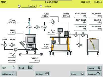
26 Process Installation | Process Start3.5 Completing the Process Setup Steps Once FlexAct® UD COM has been set up as described in Chapter 3 Process
Installation | Process Start, the System is process-ready | ready for “Ultrafiltration |
Diafiltration” as illustrated in the example in the figure below.
Fig. 3-1: Complete process setup of FlexAct® UD COM (process “Ultrafiltration | Diafiltration”)
All power lines must be connected and switched on.
The clips on all tubing supplying the medium must be open.
y To conclude the startup procedure, you should read 3.6 Valve Matrix and
4.4 Predefined Phases and Process Example.
Process Installation | Process Start 273.6 Valve Matrix
FlexAct UD valve matrix
Phase Step V1 V2 V3 V4 V5 V6 V7 V8 V9
Valve position Feed Buffer Venting Retentate Retentate Retentate Permeate Permeate Permeate
inlet inlet line recirc pinch drain XL XL drain pinch
tank pinch pinch
Flushing
Q_Fill_up close open close* close open open close close close
Q_flush close open open close open open open open close
*initial
use
Filling Q_prep_fil open open close* close open open close close close
*initial
use
Draining Q_prep_drain close close open close open open close close close
Phase Step V1 V2 V3 V4 V5 V6 V7 V8 V9
Valve position Feed Buffer Venting Retentate Retentate Retentate Permeate Permeate Permeate
inlet inlet line recirc pinch drain XL XL drain pinch
tank pinch pinch
Con-Di-Con
Q_Prep_Conc open close open open close open close close open
S_Init_ open close open open close open close close open
Concentration
S_Concentration Open close open open close adjust open close open
Pout
Q_End_ Close open open open close adjusted open close open
Concentration
Diatr-Con
Q_Prep_Conc close open open open close open close close open
S_Init_ close open open open close open close close open
Concentration
S_Concentration open close open open close adjust open close open
Pout
Q_End_ Close open open open close adjusted open close open
Concentration
Concentr.
Q_Prep_Conc close open open open close open close close open
S_Init_ close open open open close open close close open
Concentration
S_Concentration open close open open close adjust open close open
Pout
28 Process Installation | Process Start4. Running the Process
4. Running the Process
with FlexAct® UD COM with FlexAct® UD COM
4.1 General The basics of operating the microbox are described in the
Principles of Operation t „Operating Instructions Manual for DCU FlexAct®”.
4.2 Process Start Start operation of FlexAct® UD COM using the touch-screen as described in the
t “Operating Instructions Manual for DCU FlexAct®”.
Switch on the main switch.
a) Position: b) Position:
ON OFF
4.3 Start Screen | The process control and display of the process parameters are touch-screen-driven
Process Control as described in the t “Operating Instructions Manual for DCU FlexAct®”.
The following main functions are available:
“Main” Main Function
The “Main” main function on FlexAct® UD COM is described in the
t “Operating Instructions Manual for DCU FlexAct®”.
“Trend” Main Function
The “Trend” main function on FlexAct® UD COM is described in the
t “Operating Instructions Manual for DCU FlexAct®”.
“Settings” System Configuration
The “Settings” system configuration on FlexAct® UD COM is described in the
t “Operating Instructions Manual for DCU FlexAct®”.
“Calibration” Sensor Calibration
Pressure Automatically zeros all pressure sensors before using a different phase.
Pre-defined Phases
Con-Di-Con Used to concentrate the product to a predefined level and to diafilter
the product subsequently using only one peristaltic pump. The tank
must be filled with the product before starting this phase.
Diafi-Conc Diafiltration of the product. At the end of this phase, the product is
concentrated to a predefined volume.
Concentr Used to concentrate the product to a predefined final level.
Flushing Used to flush all lines with solution.
Filling Used to fill the tank or bag with product.
Running the Process with FlexAct® UD COM 294.4 Predefined Phases and tH
old the folded bag on both arms, with the magnetic clamp at the bottom, and
Process Example the filling lines facing you.
t Insert the folded bag into the Palletank®. The magnetic clamp is used to:
– facilitate the insertion in the Palletank®
– ensure that the bag will stay centred during the initial step of the
filling operation.
t The bag must remain folded until its insertion into the Palletank® to:
– prevent from exposure to any sharp edges,
– prevent from creation of creases.
t SSB recommends to perform a visual inspection of the bag during insertion into
the Palletank®.
tR
emove the adhesive tape and the foam,
tA
djust the tubings and add the sliding gate,
tC
lose the hinged front door and secure the locking system,
tC
lose the pinch clamps as close as possible to the bottom ports,
tC
onnect the water supply to the filling line and open the related pinch clamp.
The bag is ready for filling!
30 Running the Process with FlexAct® UD COMVenting filter line installation
Connect the holding device for the tubing and cartridge with the pressure transducer
BH8 - Sartofluor®
to the stand for the venting filter mounted to the Palletank for Magnetic Mixer.
HINT: Connect the Opta® as shown in the section “Connection of feed and retentate
line via Opta®”
Opta® sterile
connector
clamp of the
venting line
pressure sensor
Tare pressure sensors
Flushing | Initial filling 50 l
After the installation of a new bag, the bag needs to be filled to the maximum
volume by activating the phase “flushing” or “filling” needs to be activated in order to
assure a correct inflation of the mixing bag. Use FILLING, to fill the bag directly with
product or FLUSHING, if a preflush is required (recommended).
t close the pinch clamp in the venting filter line
Running the Process with FlexAct® UD COM 31Pull the bag’s top corners to keep it
levelled and to prevent the tubing
of the venting filter line to be in
between bag and Palletank.
Do not attempt to mix in dry bags. It may result in damage of the film.
Hint: When an new not inflated bag is filled, the pinch clamp oft he venting line
needs to be closed in order to allow a proper inflation!
Hint: For initial use the bag the bag needs to be filled with a minimum amount of
50 l to inflate the bag correctly.
t close the pinch clamp in the retentate line
t close the Biovalve XXL in the permeate
Start phase filling or flushing and follow the instructions.
Installation of the bag holder
Install the powder bag holder for optimized support of the bag - when the bag is
filled.
bag holder
bag holder
Flushing
Used to flush all lines with solution.
t Start flushing
t “Open/close the manual valves for flushing. Press ok to continue.”
t Drain line: remove the sealing plug
32 Running the Process with FlexAct® UD COMt Open Biovalve XXL in permeate
t Pinch clamp retentate is closed
t Throttle the Biovalve XXL in the retentate slowly
t Open pinch clamp in venting line if the bag was inflated before – otherwise close.
t “Fill up the vessel automatically [1] or manually [2] ?” Press [1] or [2]
t Confirm [2]: “Fill tank manually! After flushing level reached press ok.”.
t Throttle the Biovalve XXL in the retentate until flushing volume retentate |
permeate is in a ratio of 1 : 1.
Running the Process with FlexAct® UD COM 33HINT: To increase the efficiency of the flushing procedure lift the bag carefully.
t “Flushing finished. Do you want do repeat?” confirm “Yes” or “No”
The process stops when the recirculation bag is nearly empty. The operator has the
possibility to restart the pump to empty the bag completely.
During pumping it is recommended to lift up the bag to allow a complete draining of
liquid from the bag. The pump needs to be stopped by pushing the OFF-button on the
screen as soon as the bag is empty
HINT: To increase the efficiency of the flushing procedure lift the bag carefully.
t “Flushing finished. Do you want do repeat?” Press “Yes” or “No”
END Flushing – Drain the liquid
Draining
t Open Biovalve XXL in the permeate line
t Close pinch clamp in retentate
t Open Biovalve XXL in the retentate line
t Drain line: open pinch clamp
t “Flushing complete. Do you want to drain the system via the pump?”
Confirm with “No” or “Yes”
t dismantle the bag holder
t lift the bag to remove remaining liquid
t “Press ok to stop the pump.”
34 Running the Process with FlexAct® UD COMConcentration
Used to concentrate the product to a predefined final level.
t Open the pinch clamp in retentate
t Drain line: close the pinch clamp
t Initially the Biovalve XXL in the permeate is closed – open it carefully after
the initialization
t Throttle the Biovalve XXL in the retentate until the retentate pressure is reached.
t “Connect the product to the system via peristaltic pump. Press ok to
start concentration.”
t “Final concentration is running” ‘L_end’ is reached
t “concentration finished”
HINT: If a floor-scale is used, do not step on it during the entire process, because the
overfilling interlock will stop the system immediately
Running the Process with FlexAct® UD COM 35Dia_Con
Diafiltration Endconcentration
Diafiltration of the product. At the end of this phase, the product is concentrated
to a predefined volume.
t “Open|close the manual valves for diafiltration & concentration. Press ok.” Confirm
t Open pinch clamp in the retentate
t Close the pinch clamp in the drain line
t Initially the Biovalve XXL in the permeate is closed – open it carefully after
the initialization
t Throttle the Biovalve XXL in the retentate until the retentate pressure is reached.
t “Connect diafiltration buffer open|close the manual valves for diafiltration buffer.
Press ok to start diafiltration.”
t “Running out of Buffer. Connect buffer the unit [1]. Start final concentration [2]”
confirm with [1] or [2]
t “final concentration finished”
36 Running the Process with FlexAct® UD COMConDiCon
Concentration Diafiltration Endconcentration
Used to concentrate the product to a predefined level and to diafilter the product
subsequently using one peristaltic pump.
The bag must be filled with product before starting this phase.
Connect pinch – product to the inlet tube with the quick couplers and open the
corresponding clamp of product supply line.
– buffer to inlet tube with the quick couplers. Keep the pinch
clamps closed.
– filtrate tube to the permeate collection bag (not in supply with
FlexAct UD)
Start the phase ConDiCon on the DCU-system and follow the instructions on the
screen. Before starting the filling step, manipulate the valves of the bag assembly
– Open the retentate pinch clamp
– Close the retentate-drain pinch clamp
– Close the permeate XL-valve
After the corresponding message in the initialisation step the XL-valve in the
permeate line needs to be opened slowly and the message needs to be confirmed.
Adjust the outlet pressure | TMP with the retentate XL-valve – the concentration is
now running.
DCU-screen the message: “Is feed bag empty ?”
– Check the level of the product supply bag and press YES to
continue with final concentration and NO to continue the
concentration. In this case the feed pump will be started and the
product will be pumped in the tank.
When there is the message “concentration finished connect........”
– Close the pinch clamp oft he product supply line
– Open the buffer supply line
Press {1} to start the diafiltration
The diafiltration is finished, if
– the bag with the buffer is empty or
– the totalizer of the buffer supply pump has reached the pre-
defined value
After the final concentration the process is completed and it is possible to remove the
concentrate with the phase draining
HINT: If a floor-scale is used, do not step on it during the entire process, because the
overfilling interlock will stop the system immediately
Running the Process with FlexAct® UD COM 37Product removal – Draining
Used to drain the product from the system.
t “Open|close the manual valves for draining. Press ok.”
t Close pinch clamp in retentate
t Open Biovalve XXL in the permeate line
t Open Biovalve XXL in the retentate line
t Drain line: open pinch clamp
t Dismantle the bag holder and lift the bag to remove remaining liquid
38 Running the Process with FlexAct® UD COMRemove remaining liquid?
t Press OK to start the pump
To “Stop” the Quattroflow
t Pump Press OK
4.5 Other Functions The other functions such as alarms and messages, troubleshooting, password system,
etc. are described in the t “Operating Instructions Manual for DCU FlexAct®” and in
the t “Calibration Handbook”.
Running the Process with FlexAct® UD COM 395. Ending the Process 5. Ending the Process
5.1 End of Process
Release any pressure in the system by opening the upper vent valve on the
capsule!
y Close all tube clips.
5.2 Concluding Processes, To end a process, you must perform the following steps
Cleaning and Maintenance
y After concluding a process, remove Crossflow filter loop from COM!
y Disconnect pump chamber from the reciruclation pump; ref. to p. 23.
y In the case of slight contamination, it suffices to clean COM with a wet cloth.
y You can clean the metal parts or using a mild detergent or alcohol.
Make that you do not cause any scratching.
y Clean the PT100 according to the manufacturer‘s instructions.
y Clean the touch-screen display with a dry cloth.
Optional Features, Special Accessories
General Notes
This section contains notes regarding components and peripheral devices that are
not supplied as standard equipment with FlexAct® t “Master Components List and
P&I Diagram”. Documents will be supplemented depending on their availability or
compiled for the customer-specific version of FlexAct® UD COM as needed.
Please contact your supplier or Sartorius Stedim Biotech GmbH directly if your
FlexAct® UD COM is equipped with components and peripheral devices that are not
described in this manual and that you have not received a separate document for.
Sartorius Stedim Systems GmbH
Service Hotline
Schwarzenberger Weg 73–79
34212 Melsungen, Germany
Phone +49.5661.716677
Fax +49.5661.713250
www.sartorius-stedim.com
40 Ending the ProcessInhalt
Einleitung
I. Einleitung
II. Abkürzungen
III. Definitionen
IV. Betriebsanleitung | Verwendungszweck
V. Dokumentaufbau
VI. Erläuterung der Symbole
VII. Sicherheitshinweise
1. Konfiguration und Ausstattung........................................................................................ 47
1.1 Systemaufbau................................................................................................................. 47
1.2 Konfiguration und Aufbau der FlexAct® UD COM............................................... 47
1.3 Steuereinheit mit Mess- und Regelsystem............................................................. 48
2. Erste Schritte | Erstinstallation......................................................................................... 49
2.1 Allgemeines...................................................................................................................... 49
2.2 Transport........................................................................................................................... 49
2.3 Prüfungen vor Aufbau und Anschluss..................................................................... 49
2.4 Anforderungen an die Anschlüsse |
Versorgungsleitungen auf Labor- und Produktionsseite................................... 50
2.5 Aufbau und Anschluss.................................................................................................. 50
2.6 Anschlüsse und Versorgungsleitungen (Standardwerte)................................... 53
2.7 Installation des Drucksensors..................................................................................... 53
2.8 Entsorgungsanlagen...................................................................................................... 55
2.9 Installation der Pumpe................................................................................................. 55
2.10 Installation des Filterhalters....................................................................................... 57
2.11 Installation der Waage................................................................................................. 57
2.12 Abschluss der Installationsarbeiten.......................................................................... 58
3. Prozessinstallation | Prozessstart..................................................................................... 59
3.1 Allgemeines...................................................................................................................... 59
3.2 Sicherheitshinweise....................................................................................................... 59
3.3 Installation des Magnetic Mixer-Tanks (Signalkabelführung)........................... 59
3.4 Einrichtung des Mischsystems................................................................................... 60
3.5 Abschluss der Prozesskonfigurationsschritte........................................................ 65
3.6 Ventilmatrix..................................................................................................................... 66
4. Durchführung eines Prozesses mit FlexAct® UD COM.............................................. 67
4.1 Allgemeines Funktionsprinzip.................................................................................... 67
4.2 Prozessstart...................................................................................................................... 67
4.3 Startbildschirm | Prozesssteuerung......................................................................... 67
Hauptfunktion „Main“ (Hauptbildschirm).............................................................. 67
Hauptfunktion „Trend“................................................................................................. 67
Systemkonfiguration „Settings“ (Einstellungen).................................................. 67
Kalibrierung der Sensoren........................................................................................... 67
4.4 Vordefinierte Phasen und Prozessbeispiel.............................................................. 68
4.5 Sonstige Funktionen .................................................................................................... 77
5. Beendigung des Prozesses.................................................................................................... 78
5.1 Prozessende..................................................................................................................... 78
5.2 Prozessabschluss, Reinigung und Wartung............................................................ 78
Optionale Funktionen, Spezialzubehör................................................................... 78
Allgemeine Hinweise..................................................................................................... 78
Inhalt 41Sie können auch lesen