Buffer Preparation with FlexAct BP - Process Example 85032-539-69
←
→
Transkription von Seiteninhalten
Wenn Ihr Browser die Seite nicht korrekt rendert, bitte, lesen Sie den Inhalt der Seite unten
Process Example

Buffer Preparation with FlexAct® BP

                  85032-539-69        Ver. 11 | 2011
Contents
Legal Notices | Impressum . . . . . . . . . . . . . . . . . . . . . . . . . . . . . . Page 2
English . . . . . . . . . . . . . . . . . . . . . . . . . . . . . . . . . . . . . . . . . . . . . . . Page 3
Deutsch . . . . . . . . . . . . . . . . . . . . . . . . . . . . . . . . . . . . . . . . . . . . . . Seite 21
Fig. Front cover: FlexAct® BP COM
Sartorius Stedim Biotech GmbH
Technical Documentation | Technische Dokumentation
August-Spindler-Strasse 11
D-37079 Goettingen
Germany | Deutschland
Internet: www.sartorius-stedim.com
E-mail: tech.pubs@sartorius-stedim.com
Printed in Germany on paper that has been bleached without any use of chlorine.
If you require mandatory information regarding specific properties of your
FlexAct® COM that goes beyond that which is described here, please contact us.
No part of this publication may be reprinted, reproduced or translated in any form or
by any means without the prior written permission of Sartorius Stedim Biotech GmbH.
FlexAct® is a registered trademark of Sartorius Stedim Biotech GmbH
Gedruckt in Deutschland auf chlorfrei gebleichtem Papier.
Wenn Sie verbindliche Informationen zu bestimmten Eigenschaften Ihres FlexAct® COM
benötigen, welche über die hier beschriebenen hinausgehen, bitten wir um Ihre
Anfrage.
Nachdruck, Übersetzung und Vervielfältigung in jeglicher Form, auch auszugsweise,
bedürfen der schriftlichen Genehmigung der Sartorius Stedim Biotech GmbH.
FlexAct® ist eingetragenes Warenzeichen der Sartorius Stedim Biotech GmbH
2 ContentsContents
Introduction . . . . . . . . . . . . . . . . . . . . . . . . . . . . . . . . . . . . . . . . . . . . . . . . . . . . . . . . . . . 4
I. Introduction . . . . . . . . . . . . . . . . . . . . . . . . . . . . . . . . . . . . . . . . . . . . . . . . . . . 4
II. Abbreviations . . . . . . . . . . . . . . . . . . . . . . . . . . . . . . . . . . . . . . . . . . . . . . . . . . 4
III. Definitions . . . . . . . . . . . . . . . . . . . . . . . . . . . . . . . . . . . . . . . . . . . . . . . . . . . . 5
IV. Operating Instructions | Document Structure . . . . . . . . . . . . . . . . . . . . . . . . 5
V. Explanation of Symbols . . . . . . . . . . . . . . . . . . . . . . . . . . . . . . . . . . . . . . . . . . 6
VI. Safety Instructions . . . . . . . . . . . . . . . . . . . . . . . . . . . . . . . . . . . . . . . . . . . . . . 6
1. Setup and Equipment . . . . . . . . . . . . . . . . . . . . . . . . . . . . . . . . . . . . . . . . . . . . . . . 9
1.1 System Overview . . . . . . . . . . . . . . . . . . . . . . . . . . . . . . . . . . . . . . . . . . . . . . . 9
1.2 Hardware . . . . . . . . . . . . . . . . . . . . . . . . . . . . . . . . . . . . . . . . . . . . . . . . . . . . . 10
1.3 Single Used . . . . . . . . . . . . . . . . . . . . . . . . . . . . . . . . . . . . . . . . . . . . . . . . . . . . 10
1.4 Customer . . . . . . . . . . . . . . . . . . . . . . . . . . . . . . . . . . . . . . . . . . . . . . . . . . . . . 10
2. Process Installation | Process Start . . . . . . . . . . . . . . . . . . . . . . . . . . . . . . . . . . . . 11
2.1 Setting up of the mixing system . . . . . . . . . . . . . . . . . . . . . . . . . . . . . . . . . . 11
2.2 Filling of mixing bag and powder addition . . . . . . . . . . . . . . . . . . . . . . . . . . 12
2.3 Setting-up of automated pH-adjustment . . . . . . . . . . . . . . . . . . . . . . . . . . . 14
2.4 Run the automated pH adjustment process . . . . . . . . . . . . . . . . . . . . . . . . . 15
2.5 Setting up of the receiving bag and filter for filtration . . . . . . . . . . . . . . . 16
2.6 Running the filtration . . . . . . . . . . . . . . . . . . . . . . . . . . . . . . . . . . . . . . . . . . . 17
3. Ending the Process . . . . . . . . . . . . . . . . . . . . . . . . . . . . . . . . . . . . . . . . . . . . . . . . . . 19
Contents 3Introduction Introduction
I. Instruction The FlexAct® BP is a standardized configurable disposable solution (CDS) dedicated
to buffer preparation in biopharmaceutical processes. The FlexAct® BP addresses the
entire development cycle and production capacity needs from 50 to 1,000L for buffer
preparation. The integration of monitoring & control features for pH, temperature,
pressure, pump speed and fluid level control is a further milestone for the implemen-
tation of process relevant single use equipment. The integrated control allows end-
users to perform other tasks during the buffer preparation operation. Combined with
a Flexel® for Magnetic Mixer1) and Palletank® the multifunctional Central Operating
Module enables the user to install, operate and monitor a fully single use unit
operation.
This document describes different models and equipment of FlexAct® COM that were
available at the time of its creation. The equipment supplied with a device does not
necessarily cover every possible type of equipment; some may differ from the descrip-
tion while others may contain additional equipment. The descriptions for the fittings
can differ from the ones in the related P&I diagram and the equipment list because
these documents are each adapted to the customer’s specific requirements.
Documentation on customer-specific designs and equipment can be separately
supplied or are available on request.
Sartorius Stedim Biotech GmbH
Customer Service
August-Spindler-Strasse 11
37079 Goettingen, Germany
Phone +49.551.308.3318
Fax +49.551.308.3755
www.sartorius-stedim.com
II. Abbreviations BI Basic Issue BP Buffer Preparation
CDS Configurable Disposable Solution
COM Central Operating Module
DCU FlexAct® Sartorius Stedim Measurement and Control System
l/L Liter
MP Media Preparation
P&I Diagram Piping & Instrumentation Diagram
SSB Sartorius Stedim Biotech
1) This product uses ATMI patented Magnetic Mixer technology!
4 IntroductionIII. Definitions FlexAct® COM FlexAct® COM ready-to-connect system with
– Trolley,
– DCU microbox
– Touch-screen
– Pump
– Filter holder | Drip tray
– Pump head supporting plate
and
– PT100 temperature sensor
Setup and Equipment Description of all component steps required to set up
FlexAct® BP | components which have to be supplied by the
customer.
Process Installation | Description of all steps required to start a process.
Process Start Process Capability Time at which the actual process, for
example buffer preparation or virus inactivation, can be
started. Process capability is reached when the initial
operations are setup to completion.
IV. Operating Instructions| FlexAct® BP COM may only be used with equipment and under operating
Intended Use conditions described in the present equipment documentation. FlexAct® COM is
basically a work platform. It accommodates all accessory parts necessary for
transferring media within biotechnological applications.
Users must be qualified to handle the system and the process-relevant media and be
aware of the hazards potentially associated with the process. Some processes may
require that FlexAct® or the workplace be equipped with additional safety features or
that precautions be otherwise taken to protect personnel and working environment.
Additional, the operator has to follow all of the contry-specific safety-laws and -rules!
Safety and warning instructions given in this document only apply to the devices and
supplement the rules and regulations the operator stipulates at the workplace for the
respective process.
© Sartorius Stedim Biotech GmbH. No guarantee is assumed for the information provided. Sartorius
reserves the right to make technical changes to the equipment or changes to this document without any
prior notice. No part of this document may be changed, or reproduced, nor is any other use permitted
without obtaining prior written permission.
Introduction 5V. Explanation of Symbols The “Warning” symbol and this formatting indicate hazards that can be
expected with a high probability and can lead to severe injuries.
The “Caution” symbol and this formatting indicate hazards that can occur
and can lead to severe injuries if the notes and instructions are not observed.
This warning indicates risks that can lead to material damage.
Instructions and notes labeled with this symbol indicate steps that must be
performed with particular care, or point to other especially important aspects
to be observed.
y The box indicates other important information.
1., 2., ... Numbered paragraphs indicate steps that should be performed consecutively in the
order listed.
t This symbol points to information referenced in another section.
VI. Safety Instructions Organizational measures on the part of the operator:
y The operator must point out the hazards to which personnel and the working
environment may be subject during the process, must provide the suitable safety
equipment, and must publish the stipulated safety requirements.
y Only operating personnel qualified to run the process may be employed for
working with FlexAct® BP; they must be aware of potential hazards, and be
thoroughly familiar with the handling of all devices.
y Non-authorized persons must be prohibited from working on FlexAct® BP.
If hazards are associated with the process (e.g. due to process-relevant media),
the workplace must be labeled with suitable danger symbols, e.g. “BIOHAZARD”
and it should be possible to cordon it off or quarantine it if the circumstances
require.
y The workplace must be suitable for the process, e.g. resistant to acids, bases or
media and must be easy to clean, decontaminate and disinfect if contaminated.
y In general, operators must wear suitable personal protective equipment
(e.g. work clothes, gloves, safety goggles as well as a facemask if appropriate).
Workplace Setup
Workplace and supply connections in the laboratory | production facility must meet
the requirements stipulated in the equipment specifications. All intended equipment
must be complete and free of defects and flaws.
6 IntroductionRisk of injury if energy supply lines are inadvertently activated
(e.g. power supply, water, gas inlet supplies).
Energy supply lines must be blocked or secured against inadvertent startup
whenever you:
Connect or disconnect laboratory connections or connections on the production
side.
Want to disassemble peripheral installations.
When transporting or moving FlexAct® BP components, be fully aware that you
are moving equipment with an extremely high weight.
Ensure that all necessary measures are taken (e.g. warning information, barriers,
safety gear, etc.) to prevent any danger of crushing or roll-over, and thereby
the risk of injury to persons.
When assembling the PT 100 temperature sensor, make sure that the bag
is filled and not to damage the sensor channel when inserting the sensor.
Pierced or damaged sensor channels will make the bag unusable!
1. Ensure that all supply media on the laboratory or production sides , e.g. water,
supply voltage etc., match the specifications t “P&I Diagram”.
2. The workplace must be able to carry FlexAct® COM and BP components with all
equipment and the intended peripheral devices. Observe the weight and the
space requirements t „Setup and Connection“. Use suitable transportation aids
when transporting FlexAct® BP components to the place of installation and | or
changing its location.
3. Secure all laboratory connections | connections on the production side carefully.
Use only the equipment provided or released for the device. Never make any technical
modifications, unless Sartorius Stedim Biotech GmbH has expressly confirmed that
this modification does not affect safe use.
5. Loosen | remove any transport locks.
6. Check all equipment carefully for damage. Use only flawless parts.
Getting Started All equipment must be assembled carefully and safely.
1. Before every startup, check the assembly and connections of all equipment.
Safety equipment, e.g. the overpressure | safety valves must meet the
specifications and be installed.
2. Palletanks | bags, tubing, and fittings must be leak-tight.
Persons should only stand around the equipment for carrying out necessary
work. Barricade off the hazardous area and indicate this with signs!
If applicable, ensure that the respective minimum volumes as described in the
t “Operating Instructions Manual for LevMixer®” are not undershot
Observe the operating limits and optimal settings for the process. Only operate
FlexAct® BP using the allowable energy supplies (power supply, water or gas supplies).
Introduction 7BIOHAZARD, hazards caused by media.
When working with hazardous materials, observe the pertinent safety
regulations and laws!
1. Adjust the measurement and control system in strict accordance with the
allowable performance data for the respective equipment t “Operating
Instructions Manual for DCU FlexAct®”.
2. Perform in-process monitoring as to whether the process parameters are
achieved as expected. Take precautions to ensure that defects or disruptions
cannot cause any hazards or damage.
After placing the tubing in the pump, always make sure to press the STOP key on
the pump.
This resets the system and is indispensable for proper functioning of the pump.
Safety at the End of Process All equipment must be assembled carefully and safely.
After concluding the process, all affected components of FlexAct® COM should be
disposed of, disinfected and cleaned in accordance with their use and as prescribed by
the respectively valid laws and regulations.
8 Introduction1. Setup and Equipment 1. Setup and Equipment
1.1 System Overview
10 9 13 11 8/12 5 4 15 1 2 3 6 7 16 14
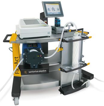
Figure 1-1: Overview FlexAct® BP COM :
Components FlexAct® COM Useful accessory
(1) Central Operating Module COM (9) Floor scale (15) Sartocheck®
(2) I-Dom with pressure transmitter (10) COMBICS1 indicator (16) BioWelder® | BioSealer®
(3) Main switch | Emergency-Power-Switch (identical for BP and MP)
(4) Pump (11) MagMixer® with palletank
(5) Pumphead support („Media Preparation“)
(6) Touch-Panel (12) SU-pH sensor
(7) Filterholder MidiCaps/MaxiCaps (13) Powder Bag
(8) PT100 RTD (14) Palletank („Storage“)
FlexAct® Buffer Preparation 91.2 Hardware – FlexAct® BP Central Operating Module
– Magnetic Mixer Drive Unit with toolbox
– Palletank® for Magnetic Mixer with load cells (FXC114155)
or Palletank® for Magnetic Mixing XC110821) on floor scale
– Palletank® for Storage
– 1 to 2 Watson-Marlow 520/R2 pumps
– Biosealer® (optional)
– Sartocheck® (optional
1.3 Single use – FlexAct® BP bag assembly 4BP110B01AB11003
– FLEXEL® Bag for Magnetic Mixer 100L (PROBE pH)
– FLEXEL® 3D Bioprocessing Bag for storage 100 L with
Sartopore® 2 Gamma Midicap
– Transfer Set (TITRATION)
1.4 Customer supply – pH standards (e.g. pH 4/7)
– Syringe with Luer connection (sampling, pH calibration)
– Acid / Base for pH correction
– Media powder
– WFI
10 FlexAct® Buffer Preparation2. Process Installation | Process Start 2. Process Installation | Process Start
The following equipment is to be used for the process of Buffer Preparation:
2.1 Setting up of the mixing system 1. Unpack the Flexel® Bag for Magnetic Mixer t Manual Flexel® Bag for Magnetic
Mixer.
2. Install the Flexel® Bags for Magnetic Mixer in the Palletank® for Magnetic Mixing
with magnetic clamp from Magnetic Mixer drive unit toolbox t Manual Flexel®
network Bag for Magnetic Mixer.
RTD 3. Connect the cable of the pH electrode to the FlexAct® COM sensor panel.
pH-sensor 4. Connect the cable of the RTD to the FlexAct® COM sensor panel. Do not put the
RTD in the thermowell of the bag.
balance
5. Calibrate the pH electrode (use pH standards and rinse with WFI finally). Use the
WM520 acid
RTD for automatic temperature compensation during calibration t Manual pH
WM520 base
probe t Manual DCU FlexAct®.
6. Connect weighing signal from the Combics weighting controller to the FlexAct®
COM sensor panel.
7. Connect the WFI supply to the bag’s inlet port.
8. Close the pinch clamps on the low port except the fill line. Close the clamps of
both acid/base top ports.
9. Tare the load cell at the combics panel t Magnetic Mixer Palletank® w/ load cells
and Combics 1 Controller.
Process Installation 11Thermowell
pH-probe with
connections for
calibration buffer
and transmission
cable
Clave connector for
sampling
2 Filling lines
Drain line (3 m) to
FlexAct® COM BP
Connections at the low port of Flexel® Bag for Magnetic Mixer (probe pH)
2.2 Filling of mixing bag 1. Fill the Flexel® Bag for Magnetic Mixer with WFI up to 80 to 95% of the final
volume. Open the 8” top port and insert the top port into the stainless steel
clamp holder. Refer to the manual of Flexel® Bag for Magnetic Mixer for the
filling of the bag and the instructions for the preparing of the buffer.
2. Remove the magnetic clamp from the bag and couple the Magnetic Mixer drive
unit under the Palletank® for Magnetic Mixer.
3. Insert the RTD in the thermowell
4. Insert the pH electrode inside the bag.
5. Start impeller rotation with the Magnetic Mixer Drive Unit.
12 Process Installation6. The pH will be logged – like all other process values – automatically by the DCU
of FlexAct® COM and the diagram of the progress can be viewed by pressing the
TREND-button of the DCU-touchscreen.
Powders can be mixed inside the same powder bag or multiple bags can be used
if appropriate. It is also possible to transfer the powder in multiple steps to
facilitate rehydration, dispersion and dissolution.
7. Connect the 8”/4” reducer (FMA114007) to the 4” port of the powder bag and
transport the powder transfer bag to the FlexAct® COM BP system.
8. Connect the powder transfer bag onto the 4” port of the Bag for Magnetic Mixer.
9. Remove the pinch clamp from the powder Transfer Bag to transfer the powder
inside the Flexel® Bags for Magnetic Mixer.
10. Mix until complete dissolution of the powders (refer to preparation instructions
provided by individual buffer supplier).
11. If more than one Powder Transfer Bag is being used, add content of the other
Powder Transfer Bags to the Palletank for Magnetic Mixer.
12. Keep the powder bag connected to the Bag for Magnetic Mixer and open one of
the ¼” top line for air removal during dilution.
13. Tare the Magnetic Mixer Palletank® w/ load cells and Combics Controller.
14. Add the remaining quantity of WFI to reach the final buffer volume, then close
the top port.
15. Mix until complete powder dissolution (refer to preparation instructions provided
by individual buffer supplier).
16. If required, remove the powder bag by opening the 4” Triclamp connection, and
close the Bag for Magnetic Mixer with the 4” plug, gasket and union clamp to
minimize exposure. Use a 4” plug kit (FMA114179) to close as well the powder bag.
17. Close the clamp at the fill line and disconnect the fill line from the water supply.
18. Record the final pH, temperature and weights values.
19. If required retrieve a buffer sample with the Luer syringe through the needleless
sampling port.
Process Installation 132.3 Setting-up of automated 1. Connect the WM 520/R2 signal cable with the corresponding plug of the sensor
pH-adjustment field. If there is a pH correction with base required connect it to the base jack,
for a correction with acid in the ACID-jack.
network 2. Select the transfer line for acid-base titration of the correct length. For Flexel
Bags for Magnetic Mixer of volumes up to 200 l a 4 m is recommended, above
RTD a length of 5 m is suitable.
pH-sensor
balance
WM520 acid
WM520 base
MagMixer tank Pos 1 Pos 2 acid
base
3. The Transfer set (Titration) consists of a tube of ¼” and a 8” ID in order to
realize different flow rates, necessary to adopt the system different buffers and
titrations agents. See table 1 for detailed values.
4. For 8” install pump at position 1, for ¼” install at position 2. Install the required
part of the Transfer set (TITRATION) in the WM 520.
t Manual Watson-Marlow 520/R2
It is necessary to install the pump in position 2, when using the ¼” tube.
5. The PID-controller for pH of the configuration is preconfigured with standard
parameters for buffers (± 1 pH from pKa) with an Xp of 2 %. Enter the correct
process parameters into the DCU screen.
MIN – Speed for acid pump
MAX – Speed for base pump
XP – Proportional share of
PID controller
DEADB,
TI, TD – not required, set to 0
14 Process InstallationTank size 50 l 100 l 200 l 400 l 650 l 1000 l
Length of transfer set
(TITRATION) 4m 4m 4m 5m 5m 5m
Max. pump speed 8”
1 N HCl/NaOH 20 % 40 % 80 % – – –
Max. pump speed ¼”
1 N HCl/NaOH – – 20 % 45 % 75 % 100 %
Max. pump speed ¼”
0,1 N HCl/NaOH % 100 % 100 % 100 % 100 % 100 %
Table 1: recommended set value for Magnetic Mixer drive unit and maximum pump speed of
WM 520 / recommended length of transfer set (TITRATION)
Pump speed 20% 40% 60% 80% 100%
Rpm WM 520 44 88 132 176 220
Flow rate 8” 80 ml/min 160 ml/min 240 ml/min 320 ml/min 400 ml/min
Flow rate ¼” 280 ml/min 560 ml/min 840 ml/min 1120 ml/min 1400 ml/min
Table 2: flow rates for ¼” and 1/8” tube in relation to different pump speeds
2.4. Run the automated pH 1. Start the pH adjustment process by selecting the pH-controller t Manual DCU
adjustment process FlexAct® COM.
2. Enter the value of the pH Set point in the box of the controller.
3. Open the clamps of the acid and base transfer line at the top port of the Flexel®
for Magnetic Mixer.
Before starting the automatic dosing process open the corresponding clamps.
A closed clamp can cause a crack of a tube. This will set media free and can
cause serious damages to equipment and injuries to persons!
4. Put the Controller Mode “Auto”.
5. If the controller mode selected to „Auto, the dosing of acid or base is running
until the pH reaches the set point of the pH adjustment.
6. If the set point has been reached, set the controller mode to „off“.
open top line
Process Installation 157. Close the clamp of the acid/base Transfer line!
8. Stop mixing.
open top line
2.5. Setting up of the receiving
bag and filter for filtration
Inlet Outlet Sampling
Connection of a Flexel® 3D bag for storage Installed MaxiCap inside the filterholder
of the FlexAct® COM
16 Process Installation2.6 Running the filtration
Start phase Filtration
Information Process values and parameters
Screenshot of DCU touchscreen
All details of the DCU-control system are described in the operating instruction
of the DCU-system t User Manual FlexAct® BP DCU.
After the filtration step is being started a modification of the weighing signal
by taring the balance or removing/adding parts of the equipment has to be
strictly avoided in order to assure a correct working of the process.
1. Start the phase “Filtration” by pushing the button on the DCU-touchscreen and
follow the instructions on the screen. The system will filter an adjustable volume
of the buffer from the Flexel® for Magnetic Mixer via a sterile filter capsule to the
receiving bag. The pump is stopped by the DCU automatically, when the adjusted
volume was transferred into the receiving bag. It is not necessary to tare the bal-
ance prior filtration, because the DCU will automatically calculates the weight
being filtered into the Flexel® 3D Bioprocessing Bag for Storage . At the begin-
ning of the sequence, there is possibility to perform a pre-filling of the tubing to
assure an higher accuracy of the weight filled in the Flexel® 3D Bioprocessing Bag
for Storage. There is also the possibility to repeat the filtration step in order to
use a manifold consisting of several bags.
Process Installation 172. During initial filling of the tubes, the speed of the pump can be modified by
change of parameter S_Pump. Stop manually, when the liquid has reached the
last Flexel® 3D Bioprocessing Bag for Storage. Open the upstream venting valve
of the MidiCaps/MaxiCaps to fill MaxiCap for venting.
3. During filtration the speed of the WM 720 pump can be set up to 100%.
In case the unit will shut down due to inlet pressure alarm, please start the
process with a reduced pumpspeed.
4. If needed The Flexel® Bag for Magnetic Mixer can be lifted at the end of the
drainage for a full buffer recovery and to minimize air pumping upstream to the
filter.
5. The filtration process stops automatically, when the „filtered weight“ was filtered
into the Flexel® 3D Bioprocessing Bags for Storage
6. After the process is finished, retrieve filtered buffer samples using the sampling
line (needleless sampling port with Luer syringe).
18 Process Installation3. Ending the Process 3. Ending the Process
Be aware, that the filter capsule can be pressurized! If so media will be set free
and can cause serious damages to equipment and injuries to persons.
Be aware, that the tube of the Transfer Set (TITRATION) can contain acid/base!
Make sure, that all acid/bases will be collected safe and properly!
1. Close the clamps of the Flexel® for Magnetic Mixer drain line.
2. Open the upstream drain valve of the filter capsule to release pressure from the
capsule.
3. Disconnect the TC connection at the filter inlet and install the blind cap to
prevent draining liquid.
4. Disconnect the SU-pressure sensor and remove the transfer tube from the
WM 720.
5. Seal the TPE tubing line between the filter outlet and Flexel® 3D Bioprocessing
Bag for Storage with a BioSealer® t Manual BioSealer® | Alternatively close the
clamp of the TPE tubing line.
6. Cut the seal | Alternatively cut the TPE tubing line between the filter and the
clamp.
7. Apply a post filtration integrity test, if required, t Manual Sartopore® 2
y-Capsules | MaxiCaps®.
8. Discard the Flexel® for Magnetic Mixer.
9. Transfer the filled buffer bag(s) to its further use.
Ending the Process 1920
Inhalt
Einleitung . . . . . . . . . . . . . . . . . . . . . . . . . . . . . . . . . . . . . . . . . . . . . . . . . . . . . . . . . . . .   22
    I.   Einleitung . . . . . . . . . . . . . . . . . . . . . . . . . . . . . . . . . . . . . . . . . . . . . . . . . . . .          22
    II.  Abkürzungen . . . . . . . . . . . . . . . . . . . . . . . . . . . . . . . . . . . . . . . . . . . . . . . . .               22
    III. Definitionen . . . . . . . . . . . . . . . . . . . . . . . . . . . . . . . . . . . . . . . . . . . . . . . . . .            23
    IV. Betriebsanleitung|Dokumentaufbau . . . . . . . . . . . . . . . . . . . . . . . . . . . . .                                   23
    V.   Erläuterung der Symbole . . . . . . . . . . . . . . . . . . . . . . . . . . . . . . . . . . . . . . . .                     24
    VI. Sicherheitshinweise . . . . . . . . . . . . . . . . . . . . . . . . . . . . . . . . . . . . . . . . . . . .                  24

1. Konfiguration und Ausstattung . . . . . . . . . . . . . . . . . . . . . . . . . . . . . . . . . . . . . 27
   1.1 Systemübersicht . . . . . . . . . . . . . . . . . . . . . . . . . . . . . . . . . . . . . . . . . . . . . . . 27
   1.2 Hardware . . . . . . . . . . . . . . . . . . . . . . . . . . . . . . . . . . . . . . . . . . . . . . . . . . . . . 28
   1.3 Einwegprodukte . . . . . . . . . . . . . . . . . . . . . . . . . . . . . . . . . . . . . . . . . . . . . . . . 28
   1.4 Vom Kunden . . . . . . . . . . . . . . . . . . . . . . . . . . . . . . . . . . . . . . . . . . . . . . . . . . . 28

2. Prozessinstallation|Prozessstart . . . . . . . . . . . . . . . . . . . . . . . . . . . . . . . . . . . . . . 29
   2.1 Einrichtung des Mischsystems . . . . . . . . . . . . . . . . . . . . . . . . . . . . . . . . . . . . 29
   2.2 Befüllung der Misch-Bags und Pulverzugabe . . . . . . . . . . . . . . . . . . . . . . . . 30
   2.3 Einrichtung der automatischen pH-Einstellung . . . . . . . . . . . . . . . . . . . . . . 32
   2.4 Durchführung der automatischen pH-Einstellung . . . . . . . . . . . . . . . . . . . . 33
   2.5 Einrichtung des aufnehmenden Bags und Filters für die Filtration . . . . . . 34
   2.6 Durchführung der Filtration . . . . . . . . . . . . . . . . . . . . . . . . . . . . . . . . . . . . . . 35

3. Beendigung des Prozesses . . . . . . . . . . . . . . . . . . . . . . . . . . . . . . . . . . . . . . . . . . . .37

                                                                                                                  Inhalt             21
Einleitung Einleitung
I. Einleitung FlexAct® BP ist eine standardisierte, konfigurierbare Einweglösung (CDS) zur Puffer-
herstellung in biopharmazeutischen Prozessen. FlexAct® BP bietet für die Pufferher-
stellung Produktionskapazitäten von 50 bis 1000 Litern und ist für den gesamten
Entwicklungszyklus vorgesehen. Die Integration der Überwachungs- und Steuerfunk-
tionen für den pH-Wert, die Temperatur, den Druck, die Pumpendrehzahl und den
Füllstand ist ein weiterer Meilenstein für die Implementierung prozessrelevanter
Einweggeräte. Dank der integrierten Steuerung können Endnutzer während der
Pufferherstellung andere Aufgaben durchführen. Der Benutzer kann mit der multi-
funktionalen zentralen Bedieneinheit sowie den Flexel® Bags für Magnetic Mixer1)
und Palletank® den Betrieb des kompletten Einwegsystems einrichten, durchführen
und überwachen.
Dieses Dokument beschreibt die verschiedenen, zum Zeitpunkt der Drucklegung ver-
fügbaren Modelle und Ausstattungen der FlexAct® COM. Die Ausstattung eines Geräts
umfasst nicht immer jede mögliche Ausstattungsart, einige Ausstattungen können
von der Beschreibung abweichen, andere können zusätzliche Funktionen enthalten.
Die Beschreibungen für die Anschlüsse können von denen im zugehörigen P&I-Dia-
gramm und der Geräteliste abweichen, da diese Dokumente jeweils an die speziellen
Anforderungen des Kunden angepasst werden.
Unterlagen zu kundenspezifischen Bauformen und Geräten können separat geliefert
werden bzw. sind auf Anfrage erhältlich.
Sartorius Stedim Biotech GmbH
Kundendienst
August-Spindler-Straße 11
D-37079 Göttingen
Telefon 0551.308.3318
Fax 0551.308.3755
www.sartorius-stedim.com
II. Abkürzungen BI Grundproblem
BP Pufferherstellung
CDS Konfigurierbare Einweglösung
COM Zentrale Bedieneinheit
DCU FlexAct®-Mess- und Regelsystem von Sartorius Stedim
l/L Liter
MP Medienherstellung
P&I-Diagramm Rohrleitungs- und Instrumentendiagramm
SSB Sartorius Stedim Biotech
1) Dieses Projekt verwendet die patentierte ATMI Magnetic Mixer-Technologie!
22 EinleitungIII. Definitionen FlexAct® COM FlexAct® COM anschlussfertiges System mit
– Wagen,
– DCU-Mikrobox
– Touchscreen
– Pumpe
– Filterhalter|Auffangvorrichtung
– Trägerplatte für Pumpenkopf
und
– PT100-Temperatursensor
Konfiguration Beschreibung aller Komponentenschritte, die zur Einrichtung
und Ausstattung von FlexAct® BP|der vom Kunden bereitgestellten Kompo-
nenten notwendig sind.
Prozessinstallation | Beschreibung aller für den Start eines Prozesses notwendigen
Prozessstart Schritte; Prozessbereitschaftszeit, d. h. die Zeit, zu der der
tatsächliche Prozess, z. B. Pufferherstellung oder Virusinakti-
vierung, begonnen werden kann. Die Prozessbereitschaft wird
nach Beendigung der ersten Schritte erreicht.
IV. Betriebsanleitung | FlexAct® BP COM darf nur mit Geräten und unter Betriebsbedingungen verwendet
Verwendungszweck werden, die in der vorliegenden Gerätedokumentation beschrieben werden. FlexAct®
COM ist im Wesentlichen eine Arbeitsplattform. Sie enthält alle Zubehörteile, die zur
Übertragung der Medien zwischen den biotechnischen Anwendungen notwendig
sind.
Die Benutzer müssen im Umgang mit dem System und den prozessrelevanten Medien
geschult sein und die potenziellen Gefahren des Prozesses kennen. Für einige Prozesse
können zusätzliche Sicherheitsvorrichtungen für FlexAct® oder den Arbeitsplatz bzw.
weitere Vorsichtsmaßnahmen zum Schutz von Personen und Arbeitsumgebung not-
wendig sein. Außerdem muss der Bediener alle länderspezifischen Sicherheitsgesetze
und -vorschriften beachten! Die Sicherheits- und Warnhinweise in diesem Dokument
beziehen sich nur auf die dazugehörigen Geräte und ergänzen die Vorschriften und
Regeln, die für den jeweiligen Prozess am Arbeitsplatz gelten.
© Sartorius Stedim Biotech GmbH. Für die dargestellten Informationen wird keine Haftung übernommen.
Sartorius behält sich das Recht vor, technische Änderungen am Gerät sowie Änderungen in diesem Doku-
ment ohne vorherige Mitteilung vorzunehmen. Ohne vorherige schriftliche Genehmigung ist es nicht
gestattet, Teile dieses Dokuments zu ändern, zu vervielfältigen oder auf sonstige Weise zu nutzen.
Einleitung 23V. Erläuterung der Symbole Das Symbol „Vorsicht“ mit dieser Formatierung weist auf Gefahren hin,
die mit hoher Wahrscheinlichkeit eintreten und zu schweren Verletzungen
führen können.
Das Symbol „Achtung“ mit dieser Formatierung weist auf Gefahren hin, die bei
Nichtbeachtung der Hinweise und Anweisungen eintreten und zu schweren
Verletzungen führen können.
Diese Warnung weist auf Risiken hin, die zu Beschädigungen führen können.
Mit diesem Symbol gekennzeichnete Anweisungen und Hinweise weisen auf
besonders genau auszuführende Schritte oder auf sonstige, besonders wichtige
Aspekte hin, die zu berücksichtigen sind.
y Dieses Symbol weist auf sonstige wichtige Informationen hin.
1., 2., ... Nummerierte Abschnitte beschreiben Schritte, die in der aufgeführten Reihenfolge
durchgeführt werden müssen.
t Dieses Symbol weist auf Informationen in einem anderen Abschnitt hin.
VI. Sicherheitshinweise Organisatorische Maßnahmen seitens des Bedieners:
y Der Bediener muss auf Gefahren hinweisen, die während des Prozesses für Perso-
nen und Arbeitsumgebung bestehen. Außerdem muss er geeignete Sicherheits-
vorrichtungen bereitstellen und die vorgesehenen Sicherheitsanforderungen
bekanntgeben.
y Für die Arbeit mit FlexAct® BP dürfen nur für den Prozess geschulte Personen
eingesetzt werden, die die potenziellen Gefahren kennen und mit dem Umgang
aller Geräte vertraut sind.
y Die Arbeit mit FlexAct® BP darf unbefugten Personen nicht gestattet werden.
Bei durch den Prozess hervorgerufenen Gefahren (z. B. durch prozessrelevante
Medien) muss der Arbeitsplatz durch entsprechende Gefahrensymbole, z. B.
„BIOGEFAHR“, gekennzeichnet werden. Außerdem sollte es möglich sein, den
Arbeitsplatz in bestimmten Situationen abzusperren bzw. zu isolieren.
y Der Arbeitsplatz muss für den Prozess geeignet sein, z. B. beständig gegenüber
Säuren, Basen bzw. Medien sein; er muss leicht zu reinigen, zu dekontaminieren
und zu desinfizieren sein.
y Generell müssen die Bediener geeignete persönliche Schutzausrüstung tragen
(z. B. Arbeitskleidung, Brillen, Sicherheitsbrillen sowie bei Bedarf eine Gesichts-
maske).
Einrichtung des Arbeitsplatzes
Der Arbeitsplatz und die Anschlüsse im Labor|der Produktionseinrichtung müssen
die Anforderungen in den Gerätespezifikationen erfüllen. Alle vorgesehenen Geräte
müssen vollständig sowie fehler- und mangelfrei sein.
24 EinleitungVerletzungsgefahr, falls Versorgungsleitungen (z. B. Strom-, Wasser-, Gaszufuhr)
unbeabsichtigt eingeschaltet werden.
Die Versorgungsleitungen müssen vor unbeabsichtigtem Einschalten gesichert
oder abgesperrt werden, wenn:
Sie die Anschlüsse des Labors|der Produktionseinrichtung trennen oder
herstellen.
Sie die Peripheriegeräte abbauen möchten.
Beim Transport|Umsetzen der FlexAct® BP-Komponenten müssen Sie das sehr
hohe Gewicht des Geräts beachten.
Es müssen alle notwendigen Maßnahmen (z. B. Warnhinweise, Barrieren, Sicher-
heitsausrüstung usw.) ergriffen werden, um eine Quetsch- oder Überrollgefahr
und damit eine Verletzungsgefahr zu vermeiden.
Beim Einbau des PT100-Temperatursensors muss der Bag gefüllt sein,
damit der Sensorkanal beim Einsetzen nicht beschädigt wird.
Sind die Sensorkanäle beschädigt oder durchstoßen, kann der Bag nicht mehr
verwendet werden!
1. Alle Versorgungsmedien auf Labor- bzw. Produktionsseite, z. B. Wasser, Strom
usw., müssen mit den Angaben im P&I-Diagramm übereinstimmen.
2. Der Arbeitsplatz muss für die FlexAct® COM- und BP-Komponenten sowie für die
gesamte Ausstattung und die vorgesehenen Peripheriegeräte geeignet sein. Das
Gewicht und den Platzbedarf im Abschnitt t „Konfiguration und Anschlüsse“
beachten. Beim Transport der FlexAct® BP-Komponenten zum Installationsort
und |oder beim Umsetzen geeignete Transporthilfen verwenden.
3. Alle Anschlüsse des Labors|der Produktionseinrichtung gründlich sichern.
Nur mitgelieferte bzw. für das Gerät freigegebene Geräte verwenden. Keine techni-
schen Änderungen vornehmen, wenn keine Bestätigung von Sartorius Stedim Biotech
GmbH vorliegt, dass die Änderung den sicheren Betrieb nicht beeinträchtigt.
5. Alle Transportsicherungen lösen|entfernen.
6. Alle Geräte sorgfältig auf Beschädigungen prüfen. Nur fehlerfreie Teile verwenden.
Erste Schritte Alle Geräte müssen sorgfältig und sicher zusammengebaut werden.
1. Vor jedem Einschalten den Zusammenbau und die Anschlüsse aller Geräte
prüfen. Sicherheitsvorrichtungen, z. B. Überdruck-|Sicherheitsventile müssen
den Anforderungen entsprechen und eingebaut sein.
2. Palletanks|Bags, Schläuche und Anschlüsse müssen leckdicht sein.
Personen sollten sich nur zur Durchführung der notwendigen Arbeiten in der
Nähe des Gerätes aufhalten. Die Gefahrenbereiche absperren und mit Schildern
kennzeichnen!
Falls zutreffend, dürfen die jeweiligen minimalen Volumina in der t „Betriebs-
anleitung für LevMixer®“ nicht unterschritten werden.
Die Betriebsgrenzen und optimalen Einstellungen für den Prozess berücksichtigen.
FlexAct® BP nur mit den zulässigen Versorgungsleitungen (Strom-, Wasser- oder
Gaszufuhr) verwenden.
Einleitung 25BIOGEFAHR, Gefahren durch Medien
Beim Umgang mit gefährlichen Stoffen die dazugehörigen Sicherheitsvorschrif-
ten und Gesetze berücksichtigen!
1. Das Mess- und Regelsystem unter genauer Beachtung der zulässigen Leistungs–
daten für das entsprechende Gerät in der t „Betriebsanleitung für DCU FlexAct®“
einstellen.
2. Mit einer Überwachung während des Prozesses prüfen, ob die Prozessparameter
wie erwartet erreicht werden. Vorsichtsmaßnahmen ergreifen, damit keine
Schäden oder Gefahren durch Mängel oder Unterbrechungen entstehen.
Nach dem Anbringen der Schläuche an der Pumpe immer auf die Taste STOP
der Pumpe drücken.
Dadurch wird das System zurückgesetzt. Das ist für die ordnungsgemäße
Funktion der Pumpe unbedingt notwendig.
Sicherheit am Ende des Prozesses Alle Geräte müssen sorgfältig und sicher zusammengebaut sein.
Am Ende des Prozesses sollten alle verwendeten Komponenten von FlexAct® COM ent-
sprechend ihrer Verwendung und den geltenden Gesetzen und Vorschriften entsorgt,
desinfiziert und gereinigt werden.
26 Einleitung1. Konfiguration und Ausstattung 1. Konfiguration und Ausstattung
1.1 Systemübersicht
10 9 13 11 8/12 5 4 15 1 2 3 6 7 16 14
Abbildung 1-1: Übersicht über FlexAct® BP COM:
FlexAct® COM-Komponenten Nützliches Zubehör
(1) Zentrale Bedieneinheit (COM) (9) Bodenwaage (15) Sartocheck®
(2) I-Dom mit Druckgeber (10) COMBICS 1-Indikator (16) BioWelder® |BioSealer®
(3) Hauptschalter|Notausschalter (gleich für BP und MP)
(4) Pumpe (11) MagMixer® mit Palletank
(5) Trägerplatte für Pumpenkopf („Medienherstellung“)
(6) Touchpanel (12) SU-pH-Sensor
(7) Filterhalter MidiCaps|MaxiCaps (13) Pulver-Bag
(8) PT100 RTD (14) Palletank („Aufbewahrung“)
FlexAct®-Pufferherstellung 271.2 Hardware – Zentrale Bedieneinheit von FlexAct® BP
– Magnetic Mixer Drive Unit mit Werkzeugkasten
– Palletank® für Magnetic Mixer mit Wägezellen (FXC114155)
oder Palletank® für Magnetic Mixer (FXC110821) auf Bodenwaage
– Palletank® zur Aufbewahrung
– 1 bis 2 Watson-Marlow 520/R2-Pumpen
– BioSealer® (optional)
– Sartocheck® (optional)
1.3 Einwegprodukte – FlexAct® BP-Bag, komplett 4BP110B01AB11003
– FLEXEL® Bag für Magnetic Mixer 100 L (pH-Sensor)
– FLEXEL® 3D Bioprocessing Bag zur Aufbewahrung 100 L mit Sartopore® 2 Gamma
MidiCap
– Transfersatz (TITRATION)
1.4 Vom Kunden – pH-Standards (z.B. pH 4/7)
– Spritze mit Luer-Anschluss (Probenahme, pH-Kalibrierung)
– Säure|Base für pH-Korrektur
– Medienpulver
– WFI
28 FlexAct®-Pufferherstellung2. Prozessinstallation|Prozessstart 2. Prozessinstallation|Prozessstart
Die folgenden Geräte werden für den Prozess der Pufferherstellung verwendet:
2.1 Einrichtung des Mischsystems 1. Den Flexel® Bag für Magnetic Mixer auspacken (t Handbuch Flexel® Bag für
Magnetic Mixer).
2. Die Flexel® Bags für Magnetic Mixer im Palletank® für Magnetic Mixer mit
der Magnetklemme aus dem Werkzeugkasten der Magnetic Mixer Drive Unit
Netzwerk einbauen (t Handbuch Flexel® Bag für Magnetic Mixer).
RTD 3. Das Kabel der pH-Elektrode mit dem Sensorfeld der FlexAct® COM verbinden.
pH-Sensor 4. Das Kabel von RDT mit dem Sensorfeld der FlexAct® COM verbinden. Den RDT
nicht in das Schutzrohr des Bags legen.
Waage
5. Die pH-Elektrode kalibrieren (pH-Standards verwenden und am Ende mit WFI
WM 520 Säure
spülen). Den RDT für die automatische Temperaturkompensation während der
WM 520 Base
Kalibrierung verwenden (t Handbuch pH-Sonde und t Handbuch DCU
FlexAct®).
6. Das Wägesignal vom Combics-Controller mit dem Sensorfeld der FlexAct® COM
verbinden.
7. Die WFI-Zufuhr mit dem Eingangsstutzen des Bags verbinden.
8. Die Klemmen am unteren Anschluss mit Ausnahme der Füllleitung schließen.
Die Klemmen der oberen Anschlüsse für Säure|Basen schließen.
9. Die Wägezelle mit dem Combics-Bedienfeld tarieren (t Magnetic Mixer
Palletank® mit Wägezellen und Combics 1-Controller).
Prozessinstallation 29Schutzrohr
pH-Sonde mit
Anschlüssen für
Kalibrierpuffer und
Übertragungskabel
Clave-Anschluss zur
Probenahme
2 Füllleitungen
Ablaufleitung (3 m)
zur FlexAct® COM
BP
Verbindungen zum unteren Anschluss des Flexel® Bags für Magnetic Mixer (pH-Sonde)
2.2 Befüllung der Misch-Bags 1. Den Flexel® Bag für Magnetic Mixer mit WFI zu ca. 80 bis 95 % des endgültigen
Volumens füllen. Den oberen 8"-Anschluss öffnen und den oberen Anschluss in
die Edelstahlklemmenhalterung einsetzen. Zur Befüllung des Bags siehe das
Handbuch Flexel® Bag für Magnetic Mixer, zur Pufferherstellung die entsprechen-
den Anweisungen.
2. Die Magnetklemme vom Bag lösen und die Magnetic Mixer Drive Unit unter dem
Palletank® für Magnetic Mixer verbinden.
3. Den RDT in das Schutzrohr einsetzen.
4. Die pH-Elektrode in den Bag einsetzen.
5. Die Rührbewegung mit der Magnetic Mixer Drive Unit beginnen.
30 Prozessinstallation6. Der pH-Wert (wie auch alle anderen Prozesswerte) wird von der DCU der FlexAct®
COM protokolliert; das Fortschrittsdiagramm kann durch Drücken der Taste
„TREND“ auf dem DCU-Touchscreen angezeigt werden.
Pulver können im gleichen Pulver-Bag oder in verschiedenen Bags gemischt
werden. Es ist auch möglich, das Pulver in mehreren Schritten einzuführen,
um die Rehydration, Dispersion und Auflösung zu erleichtern.
7. Das 8"/4"-Reduzierstück (FMA114007) am 4"-Anschluss des Pulver-Bags
anschließen und den Pulvertransfer-Bag zum FlexAct® COM BP-System
transportieren.
8. Den Pulvertransfer-Bag mit dem 4"-Anschluss des Bags für Magnetic Mixer
verbinden.
9. Die Klemme vom Pulvertransfer-Bag lösen, um das Pulver in die Flexel® Bags für
Magnetic Mixer einzufüllen.
10. Solange mischen, bis das Pulver vollständig aufgelöst ist (siehe Herstellungs-
hinweise der einzelnen Pufferlieferanten).
11. Bei Verwendung von mehr als einem Pulvertransfer-Bag den Inhalt des anderen
Pulvertransfer-Bag in den Palletank für Magnetic Mixer geben.
12. Während der Verdünnung den Pulver-Bag mit dem Bag für Magnetic Mixer
verbunden lassen und eine der oberen ¼"-Leitungen zur Entlüftung öffnen.
13. Den Palletank® für Magnetic Mixer mit den Wägezellen und dem Combics-
Controller tarieren.
14. Die restliche WFI-Menge hinzugeben, um das endgültige Puffervolumen zu
erreichen. Anschließend den oberen Anschluss schließen.
15. Solange mischen, bis das Pulver vollständig aufgelöst ist (siehe die Herstellungs-
hinweise der einzelnen Pufferlieferanten).
16. Ggf. den Pulver-Bag durch Öffnen des 4"-TriClamp-Anschlusses abnehmen und
den Bag für Magnetic Mixer mit dem 4"-Stopfen, der Dichtung und der Klemm-
verschraubung schließen, um den Kontakt zu minimieren. Den Pulver-Bag eben-
falls mit einem 4"-Stopfensatz (FMA114179) schließen.
17. Die Klemme an der Füllleitung schließen und die Füllleitung von dem Wasser-
zulauf trennen.
18. Den endgültigen pH-Wert, die Temperatur sowie die Gewichte notieren.
19. Ggf. mit der Luer-Spritze eine Pufferprobe durch den nadellosen Probenahme-
anschluss entnehmen.
Prozessinstallation 312.3 Einrichtung der automatischen 1. Das WM 520/R2-Signalkabel mit dem entsprechenden Anschluss am Sensorfeld
pH-Einstellung verbinden. Das Kabel zur Korrektur des pH-Werts durch Zugabe einer Base mit
der Basenanschlussbuchse verbinden, zur Korrektur mit Säure mit der Säuren–
anschlussbuchse.
Netzwerk
2. Die Transferleitung für die Säure-|Basentitration in der richtigen Länge auswäh-
RTD len. Für Flexel Bags für Magnetic Mixer mit Volumen bis 200 Litern wird eine
Länge von 4 m empfohlen, für größere Volumen ist eine Länge von 5 m geeignet.
pH-Sensor
Waage
WM 520 Säure
WM 520 Base
MagMixer tank Pos 1 Pos 2 acid
base
3. Der Transfersatz (Titration) besteht aus einem ¼"-Schlauch und einem 8"-
Schlauch (Innendurchmesser). Dadurch sind verschiedene Durchflussraten mög-
lich, mit denen das System an verschiedene Puffer und Titrationsmittel angepasst
werden kann. Detaillierte Werte finden Sie in Tabelle 1.
4. Bei 8" die Pumpe in Position 1 installieren; bei ¼" in Position 2. Das benötigte
Teil des Transfersatzes (TITRATION) in die WM 520 einbauen.
t Handbuch Watson-Marlow 520/R2
Bei Verwendung des ¼"-Schlauchs muss die Pumpe in Position 2 installiert
werden.
5. Der PID-Controller für den pH-Wert ist mit Standardparametern für Puffer
(±1 pH von pKa) mit Xp = 2 % vorkonfiguriert. Die korrekten Prozessparameter
in den DCU-Bildschirm eingeben.
MIN – Drehzahl für Säurepumpe
MAX – Drehzahl für Basenpumpe
XP – Proportionaler Anteil des
PID-Controllers
DEADB,
TI, TD – nicht benötigt,
auf 0 eingestellt
32 ProzessinstallationTankgröße 50 l 100 l 200 l 400 l 650 l 1000 l
Länge des Transfersatzes
(TITRATION) 4m 4m 4m 5m 5m 5m
Max. Pumpendrehzahl 8"
1 N HCl/NaOH 20 % 40 % 80 % – – –
Max. Pumpendrehzahl ¼"
1 N HCl/NaOH – – 20 % 45 % 75 % 100 %
Max. Pumpendrehzahl ¼"
0,1 N HCl/NaOH % 100 % 100 % 100 % 100 % 100 %
Tabelle 1: Empfohlener Einstellwert für die Magnetic Mixer Drive Unit sowie maximale
Pumpendrehzahl der WM 520/empfohlene Länge des Transfersatzes (TITRATION)
Pumpen-
drehzahl 20% 40% 60% 80% 100%
U/min WM 520 44 88 132 176 220
Durchflussrate 8" 80 ml/min 160 ml/min 240 ml/min 320 ml/min 400 ml/min
Durchflussrate ¼" 280 ml/min 560 ml/min 840 ml/min 1120 ml/min 1400 ml/min
Tabelle 2: Durchflussrate für ¼"- bzw. 8"-Schlauch bezogen auf verschiedene Pumpendreh-
zahlen
2.4. Durchführung der 1. Die pH-Einstellung durch Auswahl des pH-Controllers beginnen (t Handbuch
automatischen pH-Einstellung DCU FlexAct® COM).
2. Den Wert des pH-Sollwerts in das Feld des Controllers eingeben.
3. Die Klemmen der Säure- und Basentransferleitungen am oberen Anschluss des
Flexel® Bags für Magnetic Mixer öffnen.
Vor Beginn der automatischen Dosierung die entsprechenden Klemmen öffnen.
Eine geschlossene Klemme kann zum Brechen eines Schlauches führen.
Das dadurch freigesetzte Medium kann zu schweren Beschädigungen am Gerät
bzw. zu Verletzungen führen!
4. Den Controller in die Betriebsart „AUTO“ setzen.
5. Bei Auswahl der Betriebsart „AUTO“ erfolgt die Dosierung der Säure bzw. Base
solange, bis der pH-Wert den Sollwert der pH-Einstellung erreicht.
Obere Leitung öffnen 6. Ist der Sollwert erreicht, die Controller-Betriebsart auf „OFF“ (aus) stellen.
Prozessinstallation 337. Die Klemme der Säure-|Basentransferleitung schließen!
8. Den Mischvorgang beenden.
Obere Leitung öffnen
2.5. Einrichtung des aufnehmenden
Bags und Filters für die Filtration
Zulauf Ablauf Probenahme
Anschluss eines Flexel® 3D Bags zur Aufbewahrung Installierte MaxiCap in der Filterhalterung
der FlexAct® COM
34 Prozessinstallation2.6 Durchführung der Filtration
Start phase Filtration
Information Process values and parameters
Screenshot des DCU-Touchscreens
Alle Einzelheiten der DCU-Steuerung werden in der Betriebsanleitung des
DCU-Systems beschrieben (t Benutzerhandbuch FlexAct® BP DCU).
Nach Beginn des Filtrationsschrittes muss eine Änderung des Wägesignals durch
Tarieren der Waage bzw. durch Hinzufügen|Wegnehmen von Teilen des Geräts
vermieden werden, um eine korrekte Ausführung des Prozesses zu gewährleisten.
1. Die Phase „Filtration“ durch Drücken der Taste auf dem DCU-Touchscreen begin-
nen und den Anweisungen auf dem Bildschirm folgen. Das System filtert ein
einstellbares Volumen des Puffers aus dem Flexel® Bag für Magnetic Mixer über
eine sterile Filterkapsel in den aufnehmenden Bag. Die Pumpe wird von der DCU
automatisch gestoppt, wenn das festgelegte Volumen in den aufnehmenden Bag
übertragen wurde. Die Waage muss vor der Filtration nicht tariert werden, da die
DCU automatisch das Gewicht berechnet, das in den Flexel® 3D Bioprocessing Bag
zur Aufbewahrung gefiltert wird. Zu Beginn des Schrittes ist eine Vorfüllung der
Schläuche möglich, damit eine höhere Genauigkeit des Gewichtes erreicht wird,
das in den Flexel® 3D Bioprocessing Bag zur Aufbewahrung gefüllt wird. Außer-
dem besteht die Möglichkeit, den Filtrationsschritt zu wiederholen, um mehrere
Bags zu verwenden.
Prozessinstallation 352. Bei der ersten Befüllung der Schläuche kann die Pumpendrehzahl durch Ände-
rung des Parameters S_Pump geändert werden. Den Vorgang manuell stoppen,
wenn die Flüssigkeit den letzten Flexel® 3D Bioprocessing Bag zur Aufbewahrung
erreicht hat. Das vorgeschaltete Entlüftungsventil der MidiCaps|MaxiCaps öffnen,
um MaxiCap für die Entlüftung zu füllen.
3. Während der Filtration kann die Drehzahl der WM 720-Pumpe auf 100 % einge-
stellt werden.
Falls die Einheit aufgrund eines Druckalarms am Zulauf heruntergefahren wird,
den Prozess mit einer niedrigeren Pumpendrehzahl erneut beginnen.
4. Ggf. den Flexel® Bag für Magnetic Mixer am Ende der Entleerung anheben, um die
gesamte Puffermenge zu entnehmen und die zum Filter geleitete Luftmenge zu
minimieren.
5. Der Filtrationsprozess stoppt automatisch, wenn das „gefilterte Gewicht“ in den
Flexel® 3D Bioprocessing Bag zur Aufbewahrung gefiltert wurde.
6. Am Ende des Prozesses die gefilterten Pufferproben mit der Probenahmeleitung
entnehmen (nadelloser Probenahmeanschluss mit Luer-Spritze).
36 Prozessinstallation3. Beendigung des Prozesses 3. Beendigung des Prozesses
Vorsicht, die Filterkapsel kann unter Druck stehen! Eventuell freigesetztes
Medium kann zu schweren Beschädigungen am Gerät bzw. zu Verletzungen
führen.
Vorsicht, der Schlauch des Transfersatzes (TITRATION) kann eine Säure|Base
enthalten! Alle Säuren|Basen müssen sicher und ordnungsgemäß aufgefangen
werden!
1. Die Klemmen an der Ablassleitung des Flexel® Bags für Magnetic Mixer schließen.
2. Das vorgeschaltete Ablassventil der Filterkapsel öffnen, um den Druck aus der
Kapsel abzulassen.
3. Die TC-Verbindung am Filterzulauf trennen und einen Blindstopfen einsetzen,
damit keine Flüssigkeit ausläuft.
4. Den SU-Drucksensor trennen und den Transferschlauch von der WM 720-Pumpe
entfernen.
5. Die TPE-Schlauchleitung zwischen Filterausgang und Flexel® 3D Bioprocessing
Bag zur Aufbewahrung mit BioSealer® verschließen (t Handbuch BioSealer®).
Alternativ die Klemme der TPE-Schlauchleitung schließen.
6. Die Versiegelung aufschneiden.|Alternativ die TPE-Schlauchleitung zwischen
Filter und Klemme aufschneiden.
7. Ggf. einen Integritätstest nach der Filtration durchführen (t Handbuch
Sartopore® 2 y-Capsules|MaxiCaps®).
8. Die Flexel® Bags für Magnetic Mixer entsorgen.
9. Die gefüllten Puffer-Bags zur weiteren Verwendung übergeben.
Beendigung des Prozesses 37Sartorius Stedim Biotech GmbH August-Spindler-Str. 11 37079 Goettingen, Germany Phone +49.551.308.0 Fax +49.551.308.32 89 www.sartorius-stedim.com Copyright by Sartorius Stedim Biotech GmbH, Goettingen, Germany. All rights reserved. No part of this publication may be reprinted or translated in any form or by any means without the prior written permission of Sartorius Stedim Biotech GmbH. The status of the information, specifications and illustrations in this manual is indicated by the date given below. Sartorius Stedim Biotech GmbH reserves the right to make changes to the technology, fea- tures, specifications and design of the equipment without notice. Status: November 2011, Sartorius Stedim Biotech GmbH, Goettingen, Germany Printed in Germany on paper that has been bleached without any use of chlorine W_FlexAct_BP · KT Publication No.: SKG6002-a11111 Ver. 11 | 2011
Sie können auch lesen