HFT 250 / HFT 2500 Electronic Flow Rate Transmitter - HYDAC
←
→
Transkription von Seiteninhalten
Wenn Ihr Browser die Seite nicht korrekt rendert, bitte, lesen Sie den Inhalt der Seite unten
Elektronischer
                              Durchflussmessumformer
                              HFT 250 / HFT 2500
                              Für Wasser / Wasserbasierende
                              Medien

                              Electronic Flow Rate
                              Transmitter
                              HFT 250 / HFT 2500
 Bedienungsanleitung          For water or water-based fluids
 (Originalanleitung)

 Instruction manual
 (Translation of original

 instructions)

Status: 03.11.2020          HYDAC ELECTRONIC GMBH      Mat. nr.: 669886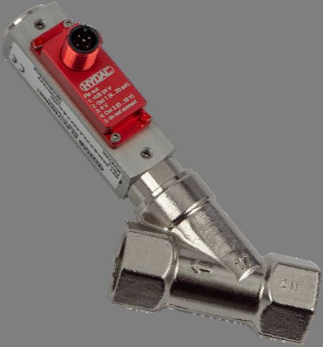
2                                                                                                             HFT 250 / HFT 2500

    Inhalt

    1      Allgemeines ______________________________________________ 4

D   2      Sicherheitshinweis ________________________________________ 5
         2.1 Allgemeine Hinweise ................................................................................................... 5
         2.2 Bestimmungsgemäße Verwendung ........................................................................... 5
         2.3 Qualifiziertes Personal ................................................................................................ 5
    3      Montage _________________________________________________ 6
         3.1 Prozessanschluss ........................................................................................................ 6
         3.2 Umgebungsbedingungen ............................................................................................ 6
    4      Elektrischer Anschluss _____________________________________ 7
    5      Technische Daten _________________________________________ 8
         5.1 Technische Daten HFT 250 ......................................................................................... 8
         5.2 Technische Daten HFT 2500 ....................................................................................... 9
    6      Bestellangaben __________________________________________ 10
         6.1 Bestellangaben HFT 250 ........................................................................................... 10
         6.2 Bestellangaben HFT 2500 ......................................................................................... 11
    7      Geräteabmessungen ______________________________________ 12
         7.1 Geräteabmessungen HFT 250 .................................................................................. 12
         7.2 Geräteabmessungen HFT 2500 ................................................................................ 13
    8      Hinweise zur Fehlersuche __________________________________ 14
    9      Wartung und Pflege _______________________________________ 14

    Stand: 03.11.2020                           HYDAC ELECTRONIC GMBH                                                  Mat. Nr.: 669886
HFT 250 / HFT 2500                                                                         3

Vorwort

                                                                                                D
                     Für Sie, den Benutzer unseres Produktes, haben wir in dieser
                     Dokumentation die wichtigsten Hinweise zum Bedienen und
                     Warten zusammengestellt.

                     Sie dient Ihnen dazu, das Produkt kennen zu lernen und seine
                     bestimmungsgemäßen Einsatzmöglichkeiten optimal zu nutzen.

                     Diese Dokumentation muss ständig am Einsatzort verfügbar
                     sein.
                     Bitte beachten Sie, dass die in dieser Dokumentation
                     gemachten Angaben der Gerätetechnik zu dem Zeitpunkt der
                     Literaturerstellung entsprechen. Abweichungen bei technischen
                     Angaben, Abbildungen und Maßen sind deshalb möglich.

                     Entdecken Sie beim Lesen dieser Dokumentation Fehler oder
                     haben weitere Anregungen und Hinweise, so wenden Sie sich
                     bitte an:

                     HYDAC ELECTRONIC GMBH
                     Technische Dokumentation
                     Hauptstraße 27
                     66128 Saarbrücken
                     -Deutschland-
                     Tel:   +49(0)6897 / 509-01
                     Fax: +49(0)6897 / 509-1726
                     Email: electronic@hydac.com

                     Die Redaktion freut sich über Ihre Mitarbeit.

                     „Aus der Praxis für die Praxis“

Stand: 03.11.2020               HYDAC ELECTRONIC GMBH                        Mat. Nr.: 669886
4 HFT 250 / HFT 2500
1 Allgemeines
Die Durchfluss-Messumformer der Serie HFT 250 und 2500 zeichnen sich durch
zuverlässige Funktion und einfache Bedienung aus. Um die Vorteile dieses Geräts in vollem
D
Umfang nutzen zu können, bitten wir folgendes zu beachten:
Jede Person, die mit der Montage, Inbetriebnahme oder Bedienung dieser Geräte
beauftragt ist, muss das Benutzerhandbuch und insbesondere die
Sicherheitshinweise gelesen und verstanden haben!
Die HYDAC Durchfluss-Messumformer der Serie HFT 250 und 2500 basieren auf einem
lage-unabhängigen Schwebekörper-Messprinzip.
Das Messmedium lenkt, unabhängig von der Einbaulage, einen federgestützten
Schwebekörper in Durchflussrichtung abhängig vom Volumenstrom aus.
Außerhalb des Gerätes und somit außerhalb des Strömungskreises ermittelt ein Hall-Sensor
die Position des Schwebekörpers. Proportional zur Auslenkung des Schwebekörpers gibt der
Sensor ein Analogsignal aus, welches dem jeweiligen Messbereich entspricht.
Die Kalibrierung des Gerätes erfolgt für senkrechten Einbau mit Durchfluss von unten nach
oben. Da das Gewicht des Schwebeköpers das Messergebnis beeinflusst, kann es bei
anderen Einbaulagen zu Abweichungen kommen.
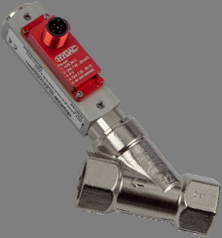
Die Geräte der Serie HFT 250 haben eine besondere Schrägsitzbauweise (Y-Bauweise) wo
der Magnet sich nicht im direkten Volumenstrom befindet. Dieses Gerät eignet sich
insbesondere für die wasserbasierenden Kühlschmierstoffe.
Stand: 03.11.2020 HYDAC ELECTRONIC GMBH Mat. Nr.: 669886HFT 250 / HFT 2500 5 2 Sicherheitshinweis 2.1 Allgemeine Hinweise Überprüfen Sie vor der Inbetriebnahme den Zustand des Gerätes sowie des evtl. mitgelieferten Zubehörs. Lesen Sie vor der Inbetriebnahme des Gerätes das Benutzerhandbuch und stellen Sie D sicher, dass das Gerät für Ihre Anwendung geeignet ist. Zur Gewährleistung eines sicheren Betriebs darf das Gerät nur nach den Angaben im Benutzerhandbuch betrieben werden. Bei der Verwendung sind zusätzlich die für den jeweiligen Anwendungsfall erforderlichen Rechts- und Sicherheitsvorschriften zu beachten. Sinngemäß gilt dies auch bei der Verwendung von Zubehör. Falsche Handhabung bzw. die Nichteinhaltung von Gebrauchshinweisen oder technischen Angaben kann zu Sach- und / oder Personenschäden führen. 2.2 Bestimmungsgemäße Verwendung Die Geräte der Serie HFT 250 und 2500 dienen zur Überwachung von kontinuierlichen Durchflüssen von Flüssigkeiten. Jeder darüberhinausgehende Gebrauch gilt als nicht bestimmungsgemäß. Sofern nicht anders angegeben, beziehen sich die Messbereiche der Geräte auf Wasser. Insbesondere Einsatzfälle, in denen stoßartige Belastungen auftreten (z.B. getakteter Betrieb), sollten vorher mit unserem technischen Vertrieb besprochen und überprüft werden. Die Geräte der Serie HFT 250 und 2500 dürfen nicht als alleiniges Mittel zur Abwendung gefährlicher Zustände an Maschinen und Anlagen eingesetzt werden. Maschinen und Anlagen müssen so konstruiert werden, dass fehlerhafte Zustände nicht zu einer für das Bedienpersonal gefährlichen Situation führen können. 2.3 Qualifiziertes Personal Die Geräte der Serie HFT 250 und 2500 dürfen nur von qualifiziertem Personal, das in der Lage ist, die Geräte fachgerecht einzusetzen, installiert werden. Qualifiziertes Personal sind Personen, die mit der Aufstellung, Montage, Inbetriebnahme und Betrieb dieser Geräte vertraut sind und die über eine ihrer Tätigkeit entsprechende Qualifikation verfügen. Stand: 03.11.2020 HYDAC ELECTRONIC GMBH Mat. Nr.: 669886
6                                                                          HFT 250 / HFT 2500

    3 Montage
    3.1 Prozessanschluss

D
              Achtung!
              Die folgenden Forderungen müssen unbedingt eingehalten werden, sonst werden
              Durchfluss-Messumformer oder Anlage beschädigt:
         - Bauseitig muss ein zum Gerät passender Prozessanschluss vorhanden sein
         - Anschlussgröße überprüfen
         - Einschraubtiefe überprüfen
         - Geeignete Dichtmittel verwenden (flüssige Dichtmittel beschädigen den Durchfluss-
          Messumformer, wenn sie hineinlaufen)
         - Fachgerecht abdichten

    3.2 Umgebungsbedingungen

         - Der Durchfluss-Messumformer darf nicht als tragendes Teil in Rohrkonstruktionen
          verwendet werden.
         - Das Medium darf keine festen Körper mit sich führen. Magnetische Partikel reichern
          sich am magnetischen Schwebekörper an und beeinträchtigen die Funktion.
         - Korrosions- und Frostschutzmittel vor dem Einsatz auf Verträglichkeit prüfen.

              Warnung!
              Die folgenden Forderungen müssen eingehalten werden, sonst kann die Funktion
              des Durchfluss-Messumformers beeinträchtigt und das Messergebnis verfälscht
              werden:

         - Externe Magnetfelder beeinflussen den Schaltkontakt. Zu Magnetfeldern (z.B.
          Elektromotoren) ausreichend Abstand einhalten.
         - Rohre, Prozessanschlüsse oder Halterungen aus ferromagnetischem Material
          beeinflussen das Magnetfeld des Durchfluss-Messumformers. Zu solchen Materialien
          (z.B. Stahl) einen Abstand von 100 mm einhalten.
         - Querschnittänderungen, Abzweigungen oder Bögen in den Rohrleitungen beeinflussen
          die Messgenauigkeit. Vor dem Gerät eine Beruhigungsstrecke von 10 x DN, hinter dem
          Gerät 5 x DN vorsehen. Niemals direkt vor dem Gerät den Rohrdurchmesser
          reduzieren!
         - Bei flüssigen Medien durch geeignete Maßnahmen die Entlüftung des Geräts
          sicherstellen.

    Stand: 03.11.2020              HYDAC ELECTRONIC GMBH                          Mat. Nr.: 669886
HFT 250 / HFT 2500 7
4 Elektrischer Anschluss
Der elektrische Anschluss erfolgt mittels eines 5-poligen M12x1 Steckers (siehe Bild).
D
Achtung!
- Elektronik-Einheit und Gehäuse sind aufeinander abgestimmt. Nach dem
Austausch einer Elektronik-Einheit muss diese werksseitig neu justiert werden.
- Pin 5 darf nicht elektrisch kontaktiert werden! Idealerweise benutzen Sie ein
4-poliges Kabel.
PIN HFT 258 - BC
HFT 25x8 - BC
1 +UB
2 4 .. 20 mA
3 GND
4 0 .. 10 V
5 reserviert
Stand: 03.11.2020 HYDAC ELECTRONIC GMBH Mat. Nr.: 6698868 HFT 250 / HFT 2500
5 Technische Daten
5.1 Technische Daten HFT 250
D
Eingangskenngrößen
Messbereiche [l/min] 2,5 .. 25
10 .. 100
Betriebsdruck [bar] 10
Druckverlust [bar] ca. 0,3
Mechanischer Anschluss siehe Geräteabmessungen / Einbaumaße
Medienberührende Teile Gehäuse: Messing vernickelt
Feder: Edelstahl 1.4571
Schauglas: DURAN® 50
Dichtungen: NBR (optional FKM, EPDM) 1)
Magnete: Hartferrit
Schwebekörper: PEEK (2,5 .. 25 l/min),
Schwebekörper Messing (10 .. 100 l/min)
alle weiteren Teile Messing vernickelt
Ausgangsgrößen
Ausgangssignal, max. Bürde 4 .. 20 mA, 3 Leiter, RLmax~ 600 Ω
max. Strom 0 .. 10 V, 3 Leiter Imax~ 10 mA
Genauigkeit ≤ ± 10 % FS
Wiederholbarkeit 2 % FS max.
Umgebungsbedingungen
Betriebstemperaturbereich -20 .. +70 °C
Mediumstemperaturbereich -20 .. +70 °C (Gerätestecker M12x1)
- Zeichen 2015/863/EU
2014/30/EU (EMV)
2011/65/EU (RoHS)
Schutzart nach DIN EN 60529 2) IP65 / IP67
Versorgungsspannung 24 V DC (19 – 30 V DC)
Sonstige Größen
Gewicht siehe Geräteabmessungen / Einbaumaße
Anmerkungen:
FS (Full Scale) = bezogen auf den vollen Messbereich
1) Andere Dichtungsmaterialien auf Anfrage
2) Bei montierter Kupplungsdose entsprechender Schutzart
Stand: 03.11.2020 HYDAC ELECTRONIC GMBH Mat. Nr.: 669886HFT 250 / HFT 2500 9
5.2 Technische Daten HFT 2500
Eingangskenngrößen
Messbereiche [l/min] Baugr. 1 Baugr. 2 Baugr. 3 Baugr. 4
D
0,005..0,06 0,02 .. 0,2 10 .. 30 0,2 .. 4,0 8 .. 90
0,04 .. 0,13 0,2 .. 0,6 15 .. 45 0,6 .. 5,0 5 .. 110
0,1 .. 0,6 0,4 .. 1,8 20 .. 60 0,5 .. 8,0 10 .. 150
0,2 .. 1,2 0,8 .. 3,2 30 .. 90 1 .. 14 35 .. 220
0,4 .. 2,0 2 .. 7 60 .. 150 1 .. 28 35 .. 250
0,5 .. 3,0 3 .. 13 2 .. 40
1,0 .. 5,0 4 .. 20 4 .. 55
8 .. 30 1 .. 70
Betriebsdruck
Messing-Ausführung 300 bar 300 bar 250 bar 200 bar
Edelstahl-Ausführung 350 bar 350 bar 300 bar 300 bar
Druckverlust [bar] 0,02 .. 0,2 0,02 .. 0,3 0,02 .. 0,4 0,02 .. 0,8
Mechanischer Anschluss siehe Geräteabmessungen / Einbaumaße
Medienberührende Teile
Messing-Ausführung Edelstahl 1.4571; Ms vernickelt; Ms; Hartferrit; Dichtung: NBR 1)
Edelstahl-Ausführung Edelstahl 1.4571; Hartferrit; Dichtung: Viton 1)
Ausgangskenngrößen
Ausgangssignal, 4 .. 20 mA, 0 .. 10 V,
max. Bürde 3-Leiter, RLmax~ 600 Ω
max. Strom 3-Leiter, Imax~ 10 mA
Genauigkeit ≤ ± 10 % FS
Wiederholbarkeit 2 % FS
Umgebungsbedingungen
Betriebstemperaturbereich -20 .. + 70 °C
Mediumstemperaturbereich -20 .. + 70 °C
- Zeichen 2014/30/EU; 2011/65/EU; 2015/863/EU
Schutzart nach IP65 / IP67
DIN EN 60529 2)
Sonstige Größen
Versorgungsspannung 24 V DC (19 .. 30 V DC)
Leistungsaufnahme10 HFT 250 / HFT 2500
6 Bestellangaben
6.1 Bestellangaben HFT 250
HFT 2 5 8 – BC – XXX – 7 – B – 1 – 000
D
Messverfahren
2 = Schwebekörper
Messmedium
5 = Wasser / Wasserbasierend
Anschlussart elektrisch
8 = Gerätestecker M12x1, 5-polig
(ohne Kupplungsdose)
Ausgangssignal
BC = Beide Signale B = 0 .. 10 V und C = 4 .. 20 V mA
Messbereiche in l/min
025 = 2,5 .. 25
100 = 10 .. 100
Genauigkeit
7 = ≤ 10,0 % FS
Gehäusewerkstoff
B = Messing (vernickelt)
Mechanische Anzeige
1 = Mit Anzeige
Modifikationsnummer
000 = Standard
Anmerkungen:
Sonderausführungen auf Anfrage.
Bei Geräten mit anderer Modifikationsnummer ist das Typenschild bzw. die mitgelieferte technische
Änderungsbeschreibung zu beachten.
Stand: 03.11.2020 HYDAC ELECTRONIC GMBH Mat. Nr.: 669886HFT 250 / HFT 2500 11
6.2 Bestellangaben HFT 2500
HFT 2 5 X X – BC – XXXX–XXXX – 5 – X – X – 000
Messverfahren
2 = Schwebekörper
Messmedium
5 = Wasser / Wasserbasierend
Anschlussart mechanisch 1)
D
1 = 1/4 “
2 = 3/8 “
3 = 1/2 “
4 = 3/4 “
5=1“
6 = 1 1/4 “
7 = 1 1/2 “
Anschlussart elektrisch
8 = Gerätestecker M12x1, 5-polig
(ohne Kupplungsdose)
Ausgangssignal
BC = Beide Signale B = 0 .. 10 V und C = 4 .. 20 V mA
Messbereiche in l/min
Baugröße 1
,005-0,06; 0,04-0,13; 00,1-00,6; 00,2-01,2; 00,4-02,0; 00,5-03,0; 01,0-05,0
Baugröße 2
0,02-00,2; 00,2-00,6; 00,4-01,8; 00,8-03,2; 02,0-07,0;
03,0-0013; 04,0-0020; 08,0-0030
Baugröße 3
0010-0030; 0015-0045; 0020-0060; 0030-0090; 0060-0150
============================================================
Baugröße 4
00,2-04,0; 00,6-05,0; 00,5-08,0; 01,0-0014; 01,0-0028; 02,0-0040; 04,0-0055;
01,0-0070; 08,0-0090; 0005-0110; 0010-0150; 0035-0220; 0035-0250;
Genauigkeit
5 = ≤ 10,0 % FS
Gehäusewerkstoff
B = Messing (vernickelt)
S = Edelstahl
Mechanische Anzeige
0 = Ohne Anzeige
1 = Mit Anzeige
Modifikationsnummer
000 = Standard
1) Mechanische Anschlussmöglichkeiten abhängig von der Gehäusebauform (siehe Geräteabmessungen).
Anmerkungen:
Sonderausführungen auf Anfrage.
Bei Geräten mit anderer Modifikationsnummer ist das Typenschild bzw. die mitgelieferte technische
Änderungsbeschreibung zu beachten.
Stand: 03.11.2020 HYDAC ELECTRONIC GMBH Mat. Nr.: 66988612 HFT 250 / HFT 2500
7 Geräteabmessungen
7.1 Geräteabmessungen HFT 250
Einbaumaße [mm]
D
Qmax G SW L1 L2 L3 T A4 D2 Gewicht,
ca. [g]
25 l/min 1/2“ 27 65 117 101 14 43 20 300
100 l/min 1“ 41 90 137 122 19 43 20 700
Stand: 03.11.2020 HYDAC ELECTRONIC GMBH Mat. Nr.: 669886HFT 250 / HFT 2500 13
7.2 Geräteabmessungen HFT 2500
Typ Einbaumaße Gewicht
(ca.)
[l/min] [mm] [g]
SW D B G DN T L
Baugröße 1
0,005..0,06
0,04..0,13
0,1..0,6
0,2..1,2 17 17 40 1/4“ 8 10 65 140
D
0,4..2,0
0,5..3,0
1,0..5,0
Baugröße 2
0,02 .. 0,2
0,2 .. 0,6
0,4 .. 1,8
0,8 .. 3,2
30 30 53 1/2 ’’ 15 14 90 520
2,0 .. 7,0
3,0 .. 13,0
4,0 .. 20,0
8,0 .. 30,0
Baugröße 3
10 .. 30
34 3/4“ 20 15 152 1290
15 .. 45 40 63
40 1“ *) 25 17 130 1110
20 .. 60
30 .. 90 40 40 63 1“ 25 17 130 1110
60 .. 150 40 40 63 1“ 25 17 130 1050
*Standard
Baugröße 4
0,2 .. 4,0
0,6 .. 5,0 1/4“ 8 10
0,5 .. 8,0 27 30 53 3/8“ 10 15 131 850
1 .. 14 1/2“ 15 14
1 .. 28
2 .. 40 27 1/2“ 15 14 146
30 53 900
4 .. 55 32 3/4“ 20 15 174
1 .. 70
34 40 63 3/4“ 20 15 152 1400
8 .. 90
40 40 63 1“ 25 17 156 1100
5 .. 110
10 .. 150 50 50 73 1 1/4“ 32 20 200 2750
35 .. 220 50 50 73 1 1/4“ 32 20 200 3000
35 .. 250 60 60 83 1 1/2“ 40 20 200 3800
Stand: 03.11.2020 HYDAC ELECTRONIC GMBH Mat. Nr.: 66988614 HFT 250 / HFT 2500
8 Hinweise zur Fehlersuche
Der Transmitter gibt kein Analogsignal aus:
1. Versorgungsspannung nicht vorhanden
D
- Versorgungsspannung überprüfen
2. Kabelbruch / Kurzschluss
- Anschlusskabel überprüfen und ggf. austauschen
3. Transmitter defekt
- Gerät zu Überprüfung an den Hersteller zurücksenden
Das Ausgangssignal stimmt nicht mit dem tatsächlichen Durchfluss überein:
1. Keine medienspezifische Skalierung
- Das Gerät zur Kalibrierung an den Hersteller zurücksenden
2. Falsch reduziert
- Gemäß Kapitel 3.2 reduzieren
3. Gerät verschmutzt
- Das Gerät reinigen
4. Gerät defekt
- Das Gerät zur Reparatur / Kalibrierung einsenden
9 Wartung und Pflege
Aufgrund der geringen Anzahl beweglicher Teile sind die Geräte sehr wartungsarm.
Eine regelmäßige Funktionskontrolle und Wartung erhöht allerdings nicht nur die
Lebensdauer und Funktionssicherheit des Geräts, sondern der ganzen Anlage.
Die Wartungsintervalle sind abhängig von
- der Verschmutzung des Mediums
- Umgebungsbedingungen (z.B. Vibrationen)
Bei der Wartung müssen mindestens folgende Punkte geprüft werden:
- Funktion des Hall-Sensors
- Dichtigkeit des Geräts
- Gängigkeit des Schwebekörpers
Es obliegt dem Betreiber, abhängig vom Anwendungsfall, geeignete Wartungsintervalle
festzulegen.
Hinweise:
- Die Gängigkeit des Schwebekörpers und die Funktion des Hall-Sensors kann überprüft
werden, indem der Durchfluss verändert und das Ausgangssignal der Elektronik-Einheit
überwacht wird.
- Zur Reinigung genügt in den meisten Fällen ein Durchspülen mit sauberem Medium. In
hartnäckigen Fällen (z.B. Kalkablagerungen) kann mit handelsüblichen Reinigern, sofern
diese die Werkstoffe des Geräts nicht angreifen, gereinigt werden.
Stand: 03.11.2020 HYDAC ELECTRONIC GMBH Mat. Nr.: 669886HFT 250 / HFT 2500 15
HYDAC ELECTRONIC GMBH
D
Hauptstr. 27
D-66128 Saarbrücken
Germany
Web: www.hydac.com
E-Mail: electronic@hydac.com
Tel.: +49 (0)6897 509-01
Fax.: +49 (0)6897 509-1726
HYDAC Service
Für Fragen zu Reparaturen steht Ihnen der HYDAC Service zur Verfügung.
HYDAC SERVICE GMBH
Hauptstr. 27
D-66128 Saarbrücken
Germany
Tel.: +49 (0)6897 509-1936
Fax.: +49 (0)6897 509-1933
Anmerkung
Die Angaben in dieser Bedienungsanleitung beziehen sich auf die beschriebenen
Betriebsbedingungen und Einsatzfälle. Bei abweichenden Einsatzfällen und/oder
Betriebsbedingungen wenden Sie sich bitte an die entsprechende Fachabteilung.
Bei technischen Fragen, Hinweisen oder Störungen nehmen Sie bitte Kontakt mit Ihrer
HYDAC-Vertretung auf.
Technische Änderungen sind vorbehalten.
Stand: 03.11.2020 HYDAC ELECTRONIC GMBH Mat. Nr.: 66988616 HFT 250 / HFT 2500
D
Stand: 03.11.2020 HYDAC ELECTRONIC GMBH Mat. Nr.: 669886Electronic Flow Rate
Transmitter
HFT 250 / HFT 2500
For water or water-based fluids
User Manual
(Translation of Original Instructions)
Edition: 2020-11-03 HYDAC ELECTRONIC GMBH Part no.: 6698862 HFT 250 / HFT 2500
Content
1 General __________________________________________________ 4
E 2 Safety Information _________________________________________ 5
2.1 General information ..................................................................................................... 5
2.2 Intended Use ................................................................................................................ 5
2.3 Qualified Staff ............................................................................................................... 5
3 Montage _________________________________________________ 6
3.1 Mechanical Process Connection ................................................................................ 6
3.2 Environmental conditions ........................................................................................... 6
4 Electrical connection_______________________________________ 7
5 Technical data ____________________________________________ 8
5.1 Technical data HFT 250 ............................................................................................... 8
5.2 Technical data HFT 2500 ............................................................................................. 9
6 Order details_____________________________________________ 10
6.1 Order details HFT 250 ................................................................................................ 10
6.2 Order details HFT 2500 .............................................................................................. 11
7 Dimensions _____________________________________________ 12
7.1 Device Dimensions HFT 250 ..................................................................................... 12
7.2 Device Dimensions HFT 2500 ................................................................................... 13
8 Troubleshooting tips ______________________________________ 14
9 Maintenance, Servicing and Care ___________________________ 14
Edition: 2020-11-03 HYDAC ELECTRONIC GMBH Part No.: 669886HFT 250 / HFT 2500 3
Preface
E
This documentation provides you, as user of our product, with
the most important notices on the operation and maintenance
of the equipment.
It will acquaint you with the product and assist you in obtaining
maximum benefit in the applications for which it is designed.
This documentation must always be kept at hand.
Please note: the specifications given in this documentation
regarding the instrument technology were correct at the time of
publishing. Modifications to technical data, illustrations and
dimensions are therefore possible.
If you discover errors while reading the documentation or have
additional suggestions or tips, please contact us at:
HYDAC ELECTRONIC GMBH
Technical documentation
Hauptstr. 27
66128 Saarbruecken
-Germany-
Phone: +49(0)6897 / 509-01
Fax: +49(0)6897 / 509-1726
Email: electronic@hydac.com
We look forward to receiving your input.
“Putting experience into practice”
Edition: 2020-11-03 HYDAC ELECTRONIC GMBH Part No.: 6698864 HFT 250 / HFT 2500
1 General
The HFT 250 and 2500 flow rate transmitter series is characterised for its reliability in
function and for its easy handling. In order to benefit fully from all the features of this
E
equipment, please observe the following:
Any person involved in the installation, commissioning or operation of this equipment
must have read and understood the user manual and in particular the safety
instructions.
The HFT 250 and 2500 series of HYDAC flow transmitters is based on the variable area float
principle and is position-independent.
Irrespective of the installation position, the test fluid deflects a spring-loaded float in the
direction of flow, depending on the flow rate.
A Hall sensor is fitted to the outside of the device and is therefore also outside the flow
circuit. In proportion to the deflection of the float, the sensor produces an analogue signal
which corresponds to the particular measuring range.
The device is calibrated for vertical installation and for an upwards flow direction. Since the
weight of the float has an effect on the measurement result, variations could occur for other
installation positions.
Due to their special angled design (Y design) the HFT 250 instruments are not directly
exposed to the volume flow. This device is particularly suited for the use in water-based
cooling lubricants.
Edition: 2020-11-03 HYDAC ELECTRONIC GMBH Part No.: 669886HFT 250 / HFT 2500 5 2 Safety Information 2.1 General information Before commissioning, check the condition of the instrument and any accessories supplied. Before commissioning, please read the user manual. Ensure that the instrument is suitable for your application. E To guarantee safe operation, the instrument may only be operated in accordance with the information in the user manual. When the instrument is in use, the statutory and safety regulations required for the particular application must be complied with. By analogy this also applies to the use of the accessories. If the instrument is not handled correctly, or if the operating instructions and specifications are not adhered to, damage to property or personal injury can result. 2.2 Intended Use The series HFT 250 and 2500 instruments are designed to monitor a continuous flow of fluids. Any other or extending use beyond this shall not be considered intended use. Unless otherwise indicated, the measurement ranges of the instruments refer to water. With particular regard to applications with intermittent loads (e.g. pulsed operation), please consult our technical sales department beforehand, so that the necessary checks can be made. Series HFT 250 and 2500 instruments must not be installed as the sole means of preventing dangerous conditions on machines and systems. Machines and systems must be designed in such a way that error conditions cannot lead to a dangerous situation for operating personnel. 2.3 Qualified Staff HFT 250 and 2500 instruments should only be installed by qualified personnel, properly trained for the suitable use of these devices. Qualified persons are those individuals who are familiar with the set-up, installation, commissioning and operation of these instruments and who have the appropriate qualification for this function. Edition: 2020-11-03 HYDAC ELECTRONIC GMBH Part No.: 669886
6                                                                              HFT 250 / HFT 2500

    3 Montage
    3.1 Mechanical Process Connection

E
               Caution!
               The following requirements must be strictly adhered to, or the flow rate transmitter
               or the system will be damaged:
         - A suitable process connection must be available on the system to connect the
         instrument.
         - Check the port size
         - Check the engagement depth
         - Use appropriate seal material (liquid sealants will damage the flow rate transmitter, if
          they flow into it)
         - Seal correctly

    3.2 Environmental conditions

         - The flow rate transmitter must not be used as a load-bearing part in pipework.
         - The fluid must not contain solid particles. Magnetic particles accumulate on the
          magnetic float and impair the function.
         - Check the compatibility of corrosion and frost protection before use.

               Warning!
               The following requirements must be complied with, otherwise the function of the
               flow rate transmitter will be impaired and the measurement results distorted:

         - External magnetic fields will affect the switching contact. Ensure sufficient distance from
          magnetic fields (e.g. electric motors)!
         - Pipes, process ports or mounting brackets in ferromagnetic material will affect the
          magnetic field of the flow rate transmitter. Ensure there is a minimum distance of
          100 mm to such materials (e.g. steel).
         - Changes in cross-section, T-pieces or elbows in the pipe affect measurement accuracy.
          Install a calming section of 10 x DN before the instrument and 5 x DN after the
          instrument. Never reduce the pipe diameter just before the instrument!
         - When used with fluids, the instrument must be vented by suitable means

    Edition: 2020-11-03             HYDAC ELECTRONIC GMBH                             Part No.: 669886
HFT 250 / HFT 2500 7
4 Electrical connection
The electrical connection is a 5 pole M12x1 plug connection (see schematic).
E
Caution!
- Electronic unit and housing are tuned to one another. If an electronic unit is
replaced, this unit must be readjusted at the factory.
- Pin 5 may not be electrically contacted! Ideally you should use a 4 wire cable.
PIN HFT 258 - BC
HFT 25x8 - BC
1 +UB
2 4 .. 20 mA
3 GND
4 0 .. 10 V
5 reserved
Edition: 2020-11-03 HYDAC ELECTRONIC GMBH Part No.: 6698868 HFT 250 / HFT 2500
5 Technical data
5.1 Technical data HFT 250
E
Input data
Measuring ranges [l/min] 2.5 .. 25
10 .. 100
Operating pressure [bar] 10
Pressure drop [bar] approx. 0.3
Mechanical connection see device dimensions / mounting dimensions
Parts in contact with fluid Housing: Brass, nickel-plated
Spring: Stainless steel 1.4571
Inspection glass: DURAN® 50
Seals: NBR (optional FKM, EPDM) 1)
Magnets: Hard ferrite
Float: PEEK (2.5 .. 25 l/min),
Variable area float: Brass (10 .. 100 l/min)
All other parts: Brass, nickel-plated
Output data
Output signal, max. load resistance 4 .. 20 mA, 3 wire, RLmax~ 600 Ω
max. current 0 .. 10 V, 3 wire, Imax~ 10 mA
Accuracy ≤ ± 10 % FS
Repeatability 2 % FS max.
Environmental Conditions
Operating temperature range -20 .. +70 °C
Fluid temperature range -20 .. +70 °C (Plug connection M12x1)
mark 2015/863/EU
2014/30/EU (EMV)
2011/65/EU (RoHS)
Protection type acc. to IP65 / IP67
DIN EN 60529 2)
Supply voltage 24 V DC (19 – 30 V DC)
Other data
Weight See device dimensions / mounting dimensions
Notes:
FS (Full Scale) = relative to complete measuring range
1) Other seal materials on request
2) With mounted mating connector in corresponding protection type
Edition: 2020-11-03 HYDAC ELECTRONIC GMBH Part No.: 669886HFT 250 / HFT 2500 9
5.2 Technical data HFT 2500
Input data
E
Measuring ranges [l/min] Size 1 Size 2 Size 3 Size 4
0.005..0.06 0.02 .. 0.2 10 .. 30 0.2 .. 4.0 8 .. 90
0.04 .. 0.13 0.2 .. 0.6 15 .. 45 0.6 .. 5.0 5 .. 110
0.1 .. 0.6 0.4 .. 1.8 20 .. 60 0.5 .. 8.0 10 .. 150
0.2 .. 1.2 0.8 .. 3.2 30 .. 90 1 .. 14 35 .. 220
0.4 .. 2.0 2 .. 7 60 .. 150 1 .. 28 35 .. 250
0.5 .. 3.0 3 .. 13 2 .. 40
1.0 .. 5.0 4 .. 20 4 .. 55
8 .. 30 1 .. 70
Operating pressure
Brass version 300 bar 300 bar 250 bar 200 bar
Stainless steel version 350 bar 350 bar 300 bar 300 bar
Pressure drop [bar] 0.02 .. 0.2 0.02 .. 0.3 0.02 .. 0.4 0.02 .. 0.8
Mechanical connection see device dimensions / mounting dimensions
Wetted components
Brass version Stainless steel 1.4571; brass nickel-pl.; brass; hard ferrite;
Seal: NBR 1)
Stainless steel version Stainless steel 1.4571; hard ferrite; Seal: Viton 1)
Output data
Output signal, max. load 4 .. 20 mA, 3 wire, RLmax~ 600 Ω
resistance, max. current 0 .. 10 V, 3 wire Imax~ 10 mA
Accuracy ≤ ± 10 % FS
Repeatability 2 % FS
Environmental Conditions
Operating temperature -20 .. 70 °C
range
Fluid temperature range -20 .. 70 °C
mark 2014/30/EU; 2011/65/EU; 2015/863/EU
Protection type acc. to IP65 / IP67
DIN EN 60529 2)
Other data
Supply voltage 24 V DC (19 .. 30 V DC)
Power consumption10 HFT 250 / HFT 2500
6 Order details
6.1 Order details HFT 250
HFT 2 5 8 – BC –XXX– 7 – B – 1 – 000
E
Measurement procedure
2 = Variable area float
Measuring fluid
5 = Water or water-based
Electrical connection
8 = M12x1 plug connector, 5 pole
(mating connector not supplied)
Output signal
BC = Both signals B = 0 .. 10 V and C = 4 .. 20 mA
Measuring ranges l/min
025 = 2,5 .. 25
100 = 10 .. 100
Accuracy
7 = ≤ 10.0 % FS
Housing material
B = Brass, nickel-plated
Mechanical indicator
1 = with analogue display
Modification number
000 = standard
Notes:
Special models on request.
For instruments with a different modification number, please read the label or the technical amendment details
supplied with the instrument.
Edition: 2020-11-03 HYDAC ELECTRONIC GMBH Part No.: 669886HFT 250 / HFT 2500 11
6.2 Order details HFT 2500
HFT 2 5 X 8 – BC – XXXX–XXXX – 5 – X – X – 000
Measurement procedure
2 = Variable area float
Measuring fluid
5 = Water or water-based
Mechanical connection 1)
E
1 = 1/4 “
2 = 3/8 “
3 = 1/2 “
4 = 3/4 “
5=1“
6 = 1 1/4 “
7 = 1 1/2 “
Electrical connection
8 = M12x1 plug connector, 5 pole
(mating connector not supplied)
Output signal
BC = Both signals B = 0 .. 10 V and C = 4 .. 20 mA
Measuring ranges l/min
Size 1
,005-0.06; 0.04-0.13; 00.1-00.6; 00.2-01.2; 00.4-02.0; 00.5-03.0; 01.0-05.0
Size 2
0.02-00.2; 00.2-00.6; 00.4-01.8; 00.8-03.2; 02.0-07.0;
03.0-0013; 04.0-0020; 08.0-0030
Size 3
0010-0030; 0015-0045; 0020-0060; 0030-0090; 0060-0150
============================================================
Size 4
00.2-04.0; 00.6-05.0; 00.5-08.0; 01.0-0014; 01.0-0028; 02.0-0040; 04.0-0055;
01.0-0070; 08.0-0090; 0005-0110; 0010-0150; 0035-0220; 0035-0250;
Accuracy
5 = ≤ 10.0 % FS
Housing material
B = Brass, nickel-plated
S = Stainless steel
Mechanical indicator
0 = without analogue display
1 = with analogue display
Modification number
000 = standard
1) Mechanical connection options depend on housing type (see dimensions)
Notes:
Special models on request.
For instruments with a different modification number, please read the label or the technical amendment details
supplied with the instrument.
Edition: 2020-11-03 HYDAC ELECTRONIC GMBH Part No.: 66988612 HFT 250 / HFT 2500
7 Dimensions
7.1 Device Dimensions HFT 250
Installation dimensions [mm]
E
Qmax G WS L1 L2 L3 T A4 D2 Weight,
approx. [g]
25 l/min 1/2“ 27 65 117 101 14 43 20 300
100 l/min 1“ 41 90 137 122 19 43 20 700
Edition: 2020-11-03 HYDAC ELECTRONIC GMBH Part No.: 669886HFT 250 / HFT 2500 13
7.2 Device Dimensions HFT 2500
Type Installation dimensions Weight
(approx.)
[l/min] [mm] [g]
WS E W G DN T L
Size 1
0.005..0.06
0.04..0.13
0.1..0.6
0.2..1.2 17 17 40 1/4“ 8 10 65 140
E
0.4..2.0
0.5..3.0
1.0..5.0
Size 2
0.02 .. 0.2
0.2 .. 0.6
0.4 .. 1.8
0.8 .. 3.2
30 30 53 1/2 ’’ 15 14 90 520
2.0 .. 7.0
3.0 .. 13.0
4.0 .. 20.0
8.0 .. 30.0
Size 3
10 .. 30
34 3/4“ 20 15 152 1290
15 .. 45 40 63
40 1“ *) 25 17 130 1110
20 .. 60
30 .. 90 40 40 63 1“ 25 17 130 1110
60 .. 150 40 40 63 1“ 25 17 130 1050
*Standard
Size 4
0.2 .. 4.0
0.6 .. 5.0 1/4“ 8 10
0.5 .. 8.0 27 30 53 3/8“ 10 15 131 850
1 .. 14 1/2“ 15 14
1 .. 28
2 .. 40 27 1/2“ 15 14 146
30 53 900
4 .. 55 32 3/4“ 20 15 174
1 .. 70
34 40 63 3/4“ 20 15 152 1420
8 .. 90
40 40 63 1“ 25 17 156 1120
5 .. 110
10 .. 150 50 50 73 1 1/4“ 32 20 200 2750
35 .. 220 50 50 73 1 1/4“ 32 20 200 3000
35 .. 250 60 60 83 1 1/2“ 40 20 200 3800
Edition: 2020-11-03 HYDAC ELECTRONIC GMBH Part No.: 66988614 HFT 250 / HFT 2500
8 Troubleshooting tips
The transmitter does not produce an analogue signal:
1. No supply voltage available
E
- Check supply voltage
2. Cable break / short circuit
- Check connecting cable and replace if necessary
3. Transmitter faulty
- Return instrument to manufacturer for investigation
The output signal does not correspond to the actual flow rate:
1. No fluid-specific scale
- Return instrument to manufacturer for calibration
2. Pipe diameter incorrectly reduced
- Reduce cross-section according to chapter 3.2
3. Instrument contaminated
- Clean the instrument
4. Instrument faulty
- Return the instrument for repair / calibration
9 Maintenance, Servicing and Care
Since there are few moving parts, the instruments require very low-maintenance.
Regular function checks and maintenance will increase not only the life expectancy and
functional safety of the instrument, but also of the whole system.
The maintenance intervals depend on
- how contaminated the fluid is
- the environmental conditions (e.g. vibrations)
As regards maintenance, the following checks must be carried out, as a minimum:
- Function of the Hall sensor
- Leak-tightness of the instrument
- Free movement of the float
It is the responsibility of the operator to determine suitable maintenance intervals, depending
on the particular application.
Notes:
- The free movement of the float and the operation of the Hall sensor can be checked by
varying the flow and observing the output signal of the electronic unit.
- As regards cleaning, flushing through with clean fluid is sufficient in most cases. In cases
where the contamination is more difficult to remove (e.g. limescale deposits), commonly
available cleaning agents can be used, providing they are compatible with the materials of
the instrument.
Edition: 2020-11-03 HYDAC ELECTRONIC GMBH Part No.: 669886HFT 250 / HFT 2500 15
HYDAC ELECTRONIC GMBH
E
Hauptstr. 27
D-66128 Saarbruecken
Germany
Web: www.hydac.com
E-Mail: electronic@hydac.com
Tel.: +49 (0)6897 509-01
Fax.: +49 (0)6897 509-1726
HYDAC Service
For enquiries regarding repairs, please contact HYDAC Service.
HYDAC SERVICE GMBH
Hauptstr. 27
D-66128 Saarbruecken
Germany
Phone: +49 (0)6897 509-1936
Fax: +49 (0)6897 509-1933
Note
The information in this manual relates to the operating conditions and applications
described. For applications and/or operating conditions not described please contact the
relevant technical department.
If you have any questions, suggestions, or encounter any problems of a technical
nature, please contact your HYDAC representative.
Subject to technical modifications.
Edition: 2020-11-03 HYDAC ELECTRONIC GMBH Part No.: 669886Sie können auch lesen