Strömungsschalter Typen VH501RF1 VH501RA1 VH501RB1 Flow switches types VH501RF1 VH501RA1 VH501RB1 - sika.net
←
→
Transkription von Seiteninhalten
Wenn Ihr Browser die Seite nicht korrekt rendert, bitte, lesen Sie den Inhalt der Seite unten

Betriebsanleitung ..................................................Seite 2 – 15
                                Operating manual ............................................... page 16 – 31
                                Notice d'utilisation ................................................page 41 - 60

                                Strömungsschalter Typen VH501RF1 • VH501RA1 • VH501RB1
                                Flow switches types VH501RF1 • VH501RA1 • VH501RB1
© SIKA • Ba_VH501 • 08/2021 .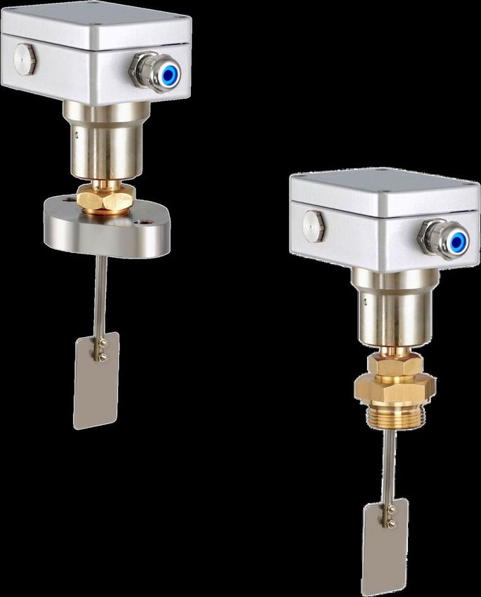
VH501

  Inhaltsverzeichnis                                                                                                     Seite
  0 Hinweise zur Betriebsanleitung ................................................................................. 3
  1 Sicherheitshinweise .................................................................................................. 4
  2 Aufbau ....................................................................................................................... 5
  3 Einbau ....................................................................................................................... 6
  3.1 Einbauhinweise ....................................................................................................... 6
  3.2 Montage .................................................................................................................. 7
  3.2.1 Montageschritte beim Strömungsschalter mit Gewinde ...................................... 7
  3.2.2 Montageschritte beim Strömungsschalter mit Flansch........................................ 8
  4 Elektrischer Anschluss .............................................................................................. 8
  5 Inbetriebnahme ....................................................................................................... 10
  6 Wartung und Rücksendung ..................................................................................... 11
  7 Demontage und Entsorgung ................................................................................... 11
  8 Technische Daten ................................................................................................... 12
  8.1 Kenndaten VH501 ................................................................................................. 12
  8.2 Werkstoffe ............................................................................................................. 13
  8.3 Abmessungen ....................................................................................................... 14

Urheberschutzvermerk
Weitergabe sowie Vervielfältigung dieser Betriebsanleitung, Verwertung und Mitteilung ihres Inhalts
sind verboten, soweit nicht ausdrücklich gestattet. Zuwiderhandlungen verpflichten zu Schadenersatz.
Alle Rechte für den Fall der Patent-, Gebrauchsmuster- oder Geschmacksmustereintragung vorbehal-
ten.

-2-                                                                                        © SIKA • Ba_VH501 • 08/2021

VH501 Hinweise zur Betriebsanleitung
0 Hinweise zur Betriebsanleitung
• Vor Gebrauch sorgfältig lesen!
• Aufbewahren für späteres Nachschlagen!
Verwendete Symbole:
GEFAHR
Nichtbeachtung hat Tod oder eine schwere Verletzung zur Folge.
WARNUNG
Nichtbeachtung kann Tod oder eine schwere Verletzung zur Folge haben.
VORSICHT
Nichtbeachtung kann eine geringfügige oder mäßige Verletzung zur Folge haben.
WICHTIG
Nichtbeachtung kann Sach- und Umweltschäden zur Folge haben.
Sollten Sie Probleme oder Fragen haben, wenden Sie sich an Ihren Lieferanten oder direkt
an:
SIKA Dr. Siebert & Kühn GmbH & Co. KG
Struthweg 7–9
34260 Kaufungen / Germany
+49 5605 803-0
+49 5605 803-555
info@sika.net
www.sika.net
Haftungsausschluss
Für Schäden und Betriebsstörungen, die durch Montagefehler, nicht bestimmungsgemäßer Verwen-
dung oder Nichtbeachtung dieser Betriebsanleitung entstehen, wird keine Haftung übernommen.
Technische Änderungen vorbehalten -3-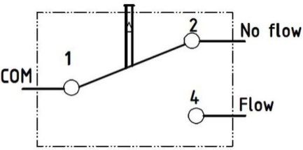
Sicherheitshinweise VH501
1 Sicherheitshinweise
Lesen Sie die Betriebsanleitung sorgfältig durch. Befolgen Sie alle Anweisungen und Hin-
weise, um Personen- oder Sachschäden zu vermeiden.
Bestimmungsgemäße Verwendung
Die SIKA-Strömungsschalter dürfen nur zur Minimum- bzw. zur Maximumüberwachung von
Flüssigkeitsströmungen verwendet werden.
WARNUNG
Die Strömungsschalter der Baureihe VH501 sind keine Sicherheitsbauteile im
Sinne der Richtlinie 2006/42/EG (Maschinenrichtlinie).
Verwenden Sie das Gerät niemals als Sicherheitsbauteil.
WICHTIG
Der Strömungsschalter kann beschädigt werden, wenn er in ungefüllten Leitun-
gen starken Vibrationen ausgesetzt wird, wie z. B. in einem Störfall mit leergelau-
fener Leitung.
Überprüfen Sie die Funktionsfähigkeit des Strömungsschalters vor der Wie-
derinbetriebnahme nach einem Störfall.
Die Betriebssicherheit des gelieferten Gerätes ist nur bei bestimmungsgemäßer Verwendung
gewährleistet. Die angegebenen Grenzwerte ( S. 12) dürfen keinesfalls überschritten wer-
den.
Überprüfen Sie vor Bestellung und Einbau, ob der Strömungsschalter werkstoffseitig für das
zu überwachende Medium geeignet ist ( S. 13).
Qualifiziertes Personal
• Das Personal, das mit der Inbetriebnahme und Bedienung des Geräts beauftragt wird,
muss eine entsprechende Qualifikation aufweisen. Dies kann durch Schulung oder ent-
sprechende Unterweisung geschehen.
• Der elektrische Anschluss darf nur von einer Elektrofachkraft vorgenommen werden.
Allgemeine Sicherheitshinweise
• Schutzart nach DIN EN 60529:
Achten Sie darauf, dass die Umgebungsbedingungen am Einsatzort die Anforderungen
der angegebenen Schutzart ( S. 12) nicht überschreiten.
• Verhindern Sie das Einfrieren des Mediums im Gerät durch geeignete Maßnahmen.
Soll der Strömungsschalter später bei Umgebungstemperaturen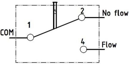
VH501 Aufbau
2 Aufbau
Gehäuseoberteil mit Deckel.
Gehäuseunterteil mit Nippel, Klemmmutter
und Flachdichtung / O-Ringen.
Prozessanschluss in unterschiedlichen Aus-
führungen:
• 2-Loch-Flansch, oval.
• 4-Loch-Flansch, rund.
• Einschraubzapfen G1 außen.
Prallfahne.
Kabelverschraubung.
Mikroschalter.
Metallbalgsystem mit Bodenring und
O-Ring.
Fahnenstange.
Zylinderschraube und Sechskantmutter für
Befestigung der Prallfahne.
Technische Änderungen vorbehalten -5-Einbau VH501
3 Einbau
Prüfen Sie vor dem Einbau, ob
die benetzten Werkstoffe des Gerätes für das verwendete Medium geeignet sind
( S. 13).
die Anlage ausgeschaltet ist und sich in einem sicheren und stromlosen Zustand befindet.
die Anlage drucklos und abgekühlt ist.
3.1 Einbauhinweise
• Der Strömungsschalter ist selbstragend und kann direkt in jede Leitung eingebaut wer-
den.
• Die bevorzugte Einbaulage ist senkrecht stehend in waagerechten Leitungen.
• Der Strömungsschalter darf max. 45° von der senkrechten Einbaulage
stehend eingebaut werden ( Abb.).
Größere Abweichungen oder Überkopfmontage sind nicht zulässig!
• In beweglichen Anlagen mit Stoß- und Vibrationsbelastungen darf der
Strömungsschalter nur senkrecht stehend in waagerechten Leitungen
eingebaut werden.
• Bei abweichenden Einbaulagen müssen Sie den Hersteller befragen.
• Die Ein- und Auslaufstrecken des Strömungsschalters müssen mindestens 5 x DN betra-
gen.
Kürzere Ein- und Auslaufstrecken haben einen direkten Einfluss auf den Schaltpunkt
und die Genauigkeit.
• Der auf dem Gehäuse des Strömungsschalters angebrachte Pfeil zeigt die einzig
mögliche Durchflussrichtung an.
Achten Sie beim Einbau darauf, dass dieser unbedingt parallel mit der Rohrachse läuft
und in Strömungsrichtung zeigt.
• Die Prallfahne muss in einem Winkel von 90° zur Strömung stehen.
• Die verwendete Prallfahne darf nicht an die Rohrwandung anstoßen.
-6- © SIKA • Ba_VH501 • 08/2021VH501 Einbau
3.2 Montage
WICHTIG
Reinigen Sie zuerst das Rohrleitungssystem bevor Sie den Strömungsschalter
einbauen.
Dadurch verhindern Sie, dass von der Montage stammende Verschmutzungen
den Strömungsschalter blockieren.
WICHTIG
• Beachten Sie die Durchflussrichtung auf dem Gerät.
• Beachten Sie die Einbaumaße ( S. 14).
Wählen Sie einen geeigneten Einbauort aus ( S. 6).
Eine senkrecht stehende Einbaulage in waagerechten Leitungen ist zu bevorzugen.
3.2.1 Montageschritte beim Strömungsschalter mit Gewinde
Installieren Sie eine passende Anschlussverschraubung am Einbauort.
Stecken Sie den Strömungsschalter mit passender Dichtung ein.
Wir empfehlen die Verwendung einer Flachdichtung.
Achten Sie bei faserigen Dichtmitteln darauf, dass keine Reste davon in die Strömung
gelangen. Dies kann zu Fehlfunktionen des Strömungsschalters führen.
Drehen Sie den Einschraubzapfen in die Anschlussverschraubung und ziehen Sie die
Verbindung fest an.
Das erforderliche Drehmoment ist abhängig von der verwendeten Flachdichtung (Her-
stellerangaben beachten!).
Ausrichten des Strömungsschalters
Überprüfen Sie die Ausrichtung der Prallfahne und die Durchflussrichtung.
Falls erforderlich:
Lösen Sie die Klemmmutter so weit, bis sich der Strömungsschalter drehen lässt.
Richten Sie den Strömungsschalter so aus, dass die Prallfahne einen Winkel von 90° zur
Strömung hat.
WICHTIG! Durchflussrichtung beachten!
Ziehen Sie die Klemmmutter wieder fest.
Maximales Drehmoment von 30 Nm beachten!
Technische Änderungen vorbehalten -7-Elektrischer Anschluss VH501
3.2.2 Montageschritte beim Strömungsschalter mit Flansch
Installieren Sie einen passenden Flanschanschluss am Einbauort.
Stecken Sie den Strömungsschalter mit passender Dichtung ein.
Achten Sie auf den richtigen Sitz der Dichtung.
WICHTIG! Durchflussrichtung beachten!
Stecken Sie die Schrauben durch die Löcher des Flansches in die Anschlussgewinde.
Drehen Sie die Schrauben soweit ein bis der Flansch kein Spiel mehr hat.
Überprüfen Sie den richtigen Sitz von Flansch und Dichtung.
Ziehen Sie die Schrauben mit einem definierten Drehmoment an.
Das erforderliche Drehmoment ist abhängig von der verwendeten Flachdichtung (Her-
stellerangaben beachten!).
Ausrichten des Strömungsschalters
Der Flansch und die Prallfahne des VH501 werden bereits werkseitig ausgerichtet, auf Dicht-
heit geprüft und versiegelt.
Ein Ausrichten des Strömungsschalters ist daher nicht erforderlich.
WICHTIG
Klemmmutter nicht lösen!
Wird die Klemmmutter am Flansch gelöst, kann der VH501 undicht werden.
4 Elektrischer Anschluss
Der elektrische Anschluss des Strömungsschalters im Inneren des Gehäuseoberteiles. Der
Anschluss erfolgt über Flachstecker und Klemmschraube (GND).
GEFAHR
Lebensgefahr durch elektrischen Strom.
Der elektrische Anschluss des Strömungsschalters darf nur von einer Elektro-
fachkraft vorgenommen werden.
Beschaltung Mikroschalter
Der Mikroschalter ist als Arbeitskontakt (Schließer) realisiert. Er
wird bei steigender Strömung geschlossen.
Deckel öffnen
Drehen Sie die Schrauben vom Deckel des Strömungs-
schalters heraus.
Nehmen Sie den Deckel mit Dichtung ab.
Legen Sie die Bauteile für die spätere Verwendung beiseite.
-8- © SIKA • Ba_VH501 • 08/2021VH501 Elektrischer Anschluss
Kabel anschließen
WICHTIG
• Das Anschlusskabel muss einen Manteldurchmesser von 4…11 mm haben
zur Gewährleistung der Schutzart nach EN 60529.
• Wählen Sie die Leitungslänge zum Klemmenblock so, dass die Leitungen
nicht unter Zug stehen. Der Deckel problemlos öffnen und schließen lassen.
Lösen Sie die Mutter der Kabelverschraubung.
TIPP!
Die Kabelverschraubung kann auch seitlich montiert werden.
Tauschen Sie die Kabelverschraubung mit einem der seitli-
chen Blindstopfen aus.
Führen Sie das Anschlusskabel durch die Kabelverschrau-
bung.
Montieren Sie passende Flachsteckhülsen an die einzelnen
Leitungen.
Stecken Sie die einzelnen Leitungen auf die Flachstecker
entsprechend der gewünschten Beschaltung des Mik-
roschalters ( oben).
WICHTIG! Schließen Sie auch die Erdung des Gehäuses
an!
Ziehen Sie die Mutter der Kabelverschraubung wieder fest.
WICHTIG
Der VH501 ist auch mit zwei, mechanisch gekoppel-
ten, Mikroschaltern als redundante Ausführung lie-
ferbar.
Deckel schließen
WICHTIG
Beim Schießen des Deckels können die Leitungen des Anschlusskabels und die
Dichtung beschädigt werden.
Achten Sie darauf, dass keine Leitungen eingeklemmt werden.
Achten Sie auf den richtigen Sitz der Dichtung.
Setzen Sie den Deckel mit Dichtung passend auf das Gehäuseoberteil.
Stecken Sie die Schrauben in den Deckel des Gehäuses.
Ziehen Sie die Schrauben fest.
Maximales Drehmoment von 2,5 Nm beachten!
Technische Änderungen vorbehalten -9-Inbetriebnahme VH501 5 Inbetriebnahme Inbetriebnahme Überprüfen Sie vor dem erstmaligen Einschalten, ob der VH501 richtig eingebaut wurde und alle Verschraubungen dicht sind. die elektrischen Anschlüsse ordnungsgemäß durchgeführt wurden. das Messsystem durch Spülen entlüftet ist. Kontaktart Der Strömungsschalter VH501 ist als Arbeitskontakt (Schließer) realisiert. Im strömungslosen Zustand ist der Mikroschalter geöffnet. Überschreitet der Durchfluss bei steigender Strömung den Schaltpunkt, wird der Mikroschal- ter geschlossen. Bei fallender Strömung wird der Mikroschalter wieder geöffnet, sobald der Durchfluss den Schaltpunkt unterschritten hat. - 10 - © SIKA • Ba_VH501 • 08/2021
VH501 Wartung und Rücksendung
6 Wartung und Rücksendung
Wartung
Der Strömungsschalter ist wartungsfrei und kann auch nicht vom Anwender repariert werden.
Bei einem Defekt muss das Gerät ausgetauscht oder zur Reparatur an den Hersteller zurück-
geschickt werden.
Rücksendung
Beachten Sie die Hinweise zum Ablauf des Rücksendeverfahrens auf unserer Website
(www.sika.net/service/rma-warenruecksendung).
7 Demontage und Entsorgung
VORSICHT
Entfernen Sie niemals einen Strömungsschalter oder seinen Prozessanschluss
aus einer unter Druck stehenden Anlage.
Sorgen Sie dafür, dass die Anlage fachgerecht ausgeschaltet wird.
Vor der Demontage
Überprüfen Sie vor der Demontage, ob
die Anlage ausgeschaltet ist und sich in einem sicheren und stromlosen Zustand befindet.
die Anlage drucklos und abgekühlt ist.
Demontage
Entfernen Sie die elektrischen Anschlüsse.
Bauen Sie den Strömungsschalter aus.
Entsorgung
Konform zu den Richtlinien 2011/65/EU (RoHS) und 2012/19/EU (WEEE)* muss das Gerät
separat als Elektro- und Elektronikschrott entsorgt werden.
KEIN HAUSMÜLL
Das Gerät besteht aus unterschiedlichen Werkstoffen. Es darf nicht zusammen
mit Hausmüll entsorgt werden.
Führen Sie den Strömungsschalter der lokalen Wiederverwertung zu
oder
schicken Sie den Strömungsschalter an Ihren Lieferanten bzw. SIKA zurück.
* WEEE-Reg.-Nr.: DE 25976360
Technische Änderungen vorbehalten - 11 -Technische Daten VH501
8 Technische Daten
Bei kundenspezifischen Ausführungen können technische Daten gegenüber den Angaben
dieser Anleitung abweichen. Bitte beachten Sie die Angaben auf dem Typenschild.
8.1 Kenndaten VH501
Typ VH501
Kenndaten Strömungsschalter
Schaltfunktion Arbeitskontakt (Mikroschalter)
- optional: mit 2 Mikroschaltern
Schaltpunkte *1 Flansch: 6,0 m3/h (DN 65)
(Wasser, 20 °C) Gewinde: 10,0 m3/h (DN 80)
Toleranz des Schaltpunktes ±15%
Elektrische Kenndaten
Kontaktbelastung, max. 48 VDC: 1 A • -/-
- ohmsche • induktive Last 110 VDC: 0,5 A • 0,2 A
250 VAC: 6 A (EN 61058-1) • -/-
Elektrischer Anschluss Flachstecker 2,8 x 0,5 mm
Kabelverschraubung M16x1,5
Schutzart (EN 60529) IP 68 und IP 69 K
Prozessgrößen
Mediumstemperatur -40…120 °C
(nicht gefrierend)
Umgebungstemperatur -40…100 °C
Lagertemperatur -40…100 °C
Nennweiten *2 DN 65 … DN 100
- optional DN 25 … DN 50
Nenndruck, max. 10 bar
Prüfdruck, max. 14 bar
Prozessanschluss 2-Loch-Flansch, oval, ohne O-Ring-Nut
4-Loch-Flansch, rund, ohne O-Ring-Nut
G1 außen
Vibrationsfestigkeit 4 g gemäß IEC 61373
*1 bei steigender Strömung, weitere Schaltpunkte auf Anfrage.
*2 bei anderen Nennweiten als DN 65 (Flansch) und DN 80 (Gewinde) ändern sich die Werte der
Schaltpunkte gegenüber den in dieser Betriebsanleitung angegebenen Werten.
Wichtig!
Beachten Sie bei abweichenden Nennweiten die Einbauhinweise ( S. 6).
- 12 - © SIKA • Ba_VH501 • 08/2021VH501 Technische Daten
8.2 Werkstoffe
Typ VH501 *1)
Gehäuseoberteil Aluminium AlSi12 • Pulverbeschichtet RAL 9006
Gehäuseunterteil Messing CW614N • Oberfläche vernickelt
Nippel Messing CW614N X
Klemmmutter Messing CW614N
Flachdichtung Tesnit BA-50 (nur Gewinde) X
Prozessanschluss:
- 2/4-Loch-Flansch Edelstahl 1.4404 X
- Gewinde G1A Messing CW614N
Metallbalgsystem Edelstahl 1.4571 X
Bodenring Messing CW614N
O-Ring(e) FVMQ X
Fahnenstange Edelstahl 1.4571 X
Prallfahne Edelstahl 1.4571 X
Zylinderschraube Edelstahl 1.4571 X
Sechskantmutter Edelstahl 1.4571 X
*1) Benetzte Bauteile.
Technische Änderungen vorbehalten - 13 -Technische Daten VH501 8.3 Abmessungen VH501 mit 2-Loch-Flansch, oval: VH501 mit 4-Loch-Flansch, rund: - 14 - © SIKA • Ba_VH501 • 08/2021
VH501                                   Technische Daten

VH501 mit Gewinde (Einschraubzapfen):

Technische Änderungen vorbehalten                  - 15 -
VH501

   Table of contents                                                                                                      page
   0 About this operating manual.................................................................................... 17
   1 Safety instructions ................................................................................................... 18
   2 Construction ............................................................................................................ 19
   3 Installation ............................................................................................................... 20
   3.1 Installation instructions .......................................................................................... 20
   3.2 Mounting ............................................................................................................... 21
   3.2.1 Mounting steps for a flow switch with thread..................................................... 21
   3.2.2 Mounting steps for a flow switch with flange ..................................................... 22
   4 Electrical connection ............................................................................................... 22
   5 Commissioning........................................................................................................ 24
   6 Maintenance and return shipment ........................................................................... 25
   7 Disassembly and disposal ....................................................................................... 25
   8 Technical data ......................................................................................................... 26
   8.1 Characteristics VH501 .......................................................................................... 26
   8.2 Materials ............................................................................................................... 27
   8.3 Dimensions ........................................................................................................... 28

Copyright notice
The reproduction, distribution and utilization of this operating manual as well as the communication
of its contents to others without express authorization is prohibited. Offenders will be held liable for
the payment of damages. All rights reserved in the event of the grant of a patent, utility model or de-
sign.

- 16 -                                                                                     © SIKA • Ba_VH501 • 08/2021
VH501 About this operating manual
0 About this operating manual
• Read carefully before use!
• Retain for later reference!
Symbols used:
DANGER
Failure to do so will result in death or serious injury.
WARNING
Failure to do so may result in death or serious injury.
CAUTION
Failure to do so may result in minor or moderate injury.
IMPORTANT
Failure to do so may result in damage to property and the environment.
If you have any problems or questions, please contact your supplier or contact us directly at:
SIKA Dr. Siebert & Kühn GmbH & Co. KG
Struthweg 7–9
34260 Kaufungen / Germany
+49 5605 803-0
+49 5605 803-555
info@sika.net
www.sika.net
Exclusion of liability
We accept no liability for any damage or malfunctions resulting from incorrect installation, inappropri-
ate use of the device or failure to follow the instructions in this operating manual.
Technical changes reserved - 17 -Safety instructions VH501
1 Safety instructions
Read through the operating manual carefully. Follow all instructions and notices to prevent
injury or damage to property.
Intended use
SIKA flow switches may only be used for minimum or maximum monitoring of liquid flows.
WARNING
The flow switches of the series VH501 are no safety component in accordance
with Directive 2006/42/EG (Machine Directive).
Never use the device as a safety component.
IMPORTANT
The flow switch can be damaged if it is exposed to strong vibrations in dry pipe-
lines, e.g. in case of an interruption with a run-empty pipeline.
Check the functionality of the flow switch before restarting after an interrup-
tion.
The operational safety of the device supplied is only guaranteed by intended use. The speci-
fied limits ( p. 25) under no circumstances be exceeded.
Before installing the device, check that the wetted materials of the device are compatible with
the media being used ( p. 27).
Qualified personnel
• The personnel who are charged for the installation, operation and maintenance of the de-
vice must hold a relevant qualification. This can be based on training or relevant tuition.
• The electrical connection should only be carried out by a fully qualified electrician.
General safety instructions
• Degree of protection according to EN 60529:
Please ensure that the ambient conditions at the site of use does not exceed the require-
ments for the stated protection rating ( p. 25).
• Prevent freezing of the medium in the device with appropriate measures.
If the flow switch is to be used in ambient temperatures ofVH501 Construction
2 Construction
Upper housing part with cover.
Lower housing part with adapter, clamping
nut and flat gasket / O-rings.
Process connection in different versions:
• 2 hole flange, oval.
• 4 hole flange, round.
• Screwed plug G1 male.
Baffle flags.
Cable gland.
Micro switch.
Metal bellows system with bottom ring and
O-ring.
Flagpole.
Cylinder screw and hexagon nut for fixing
the baffle flags.
Technical changes reserved - 19 -Installation VH501
3 Installation
Before installing, check that
the wetted materials of the device are suitable for the media being used ( p. 27).
the equipment is switched off and is in a safe and de-energised state.
the equipment is depressurised and has cooled down.
3.1 Installation instructions
• The flow switch is self-supporting and can therefore be fitted in any pipeline.
• The preferred installation position is upright vertical in horizontal pipelines.
• Install the flow switch max. 45° from the vertical installation position
( Fig.).
Larger deviations and upside down installations are impermissible!
• In movable systems subjected to impact or vibration stresses, the flow
switch should only be installed vertically in horizontal pipelines.
• In case of deviating installation positions consult the manufacturer.
• The inlet and outlet lines of the flow switch must be at least 5 x DN.
Shorter inlet and discharge routes have a direct influence on the setpoint and the accu-
racy.
• The arrow attached to the housing of the flow switch indicates the only possible flow
direction.
During installation, make sure that it runs parallel with the axis of the pipe and in the
direction of flow.
• The baffle flag must stand at an angle of 90° to the flow.
• The used baffle flag must not hit the pipe wall.
- 20 - © SIKA • Ba_VH501 • 08/2021VH501 Installation
3.2 Mounting
IMPORTANT
Firstly, clean the pipe system before installing the flow switch.
That prevents dirt originating from the assembly from blocking the flow switch.
IMPORTANT
• Pay attention to the flow direction on the device.
• Pay attention to the mounting dimensions ( p. 28).
Select an appropriate location for installation ( p. 20).
A vertical installation position in horizontal lines is preferred.
3.2.1 Mounting steps for a flow switch with thread
Install the appropriate screwed connections at the installation location.
Insert the flow switch with a suitable gasket.
We recommend the use of a flat gasket.
With fibrous sealants, ensure that no residues can get into the flow. They can lead to
malfunctions of the flow switch.
Turn the threaded plug into the screw connector and tighten it.
The required torque is dependent on the flat seal being used (comply with the manu-
facturer's specifications!).
Align the flow switch
Check the alignment of the baffle flag and the direction of flow.
If necessary:
Loosen the clamping nut until the flow switch can be turned.
Align the flow switch so that the baffle flag is set at an angle of 90° to the flow.
IMPORTANT! Comply with the direction of flow!
Tighten the clamping nut again.
Pay attention to the maximum torque of 30 Nm!
Technical changes reserved - 21 -Electrical connection VH501
3.2.2 Mounting steps for a flow switch with flange
Install an appropriate flange connection at the installation location.
Insert the flow switch with a suitable gasket.
Ensure that the gasket is properly seated.
IMPORTANT! Observe flow direction!
Insert the screws through the holes of the flange into the connection threads.
Turn the screws until the flange no longer has any play.
Check the proper fit of flange and gasket.
Tighten the screws with a defined torque.
The required torque depends on the gasket used
(comply with the manufacturer’s specifications!).
Align the flow switch
The flange and the baffle flag of the VH501 have already been aligned in the factory, tested
for leakage and sealed.
Therefore, do not align the flow switch.
IMPORTANT
Do not unscrew the clamping nut!
If the clamping nut on the flange is unscrewed, the VH501 can leak.
4 Electrical connection
The electrical connection of the flow switch is located inside of the upper housing part. The
connection is made by Q.C. terminals and clamping screw (GND).
DANGER
Risk of death due to electric current.
De-energize the electrical system before connecting the flow switch.
Wiring of micro switch
The micro switch is made as a normally open contact (NOC). It
closes when the flow increases.
Open the cover
Turn out the screws from the cover of the flow switch.
Remove the cover with gasket.
Place these parts aside for later use.
- 22 - © SIKA • Ba_VH501 • 08/2021VH501 Electrical connection
Connecting the cable
IMPORTANT
• The connection cable must have a sheath diameter of 4…11 mm to ensure
the degree of protection according to EN 60529.
• Select the cable length to the terminal block so that the cables are not under
tension. It should be possible to open and close the cover without any prob-
lems.
Loosen the nut of the cable gland.
TIP!
The cable gland can also be mounted laterally. Replace the
cable gland with one of the lateral blanking plugs.
Feed the connecting cable through the cable gland.
Install suitable flat-blade connectors to the individual cables.
Insert the individual cables in the flat connectors correspond-
ing to the wiring of the micro switch ( top).
IMPORTANT! Connect the grounding of the housing!
Tighten the nut of the cable gland again.
IMPORTANT
The VH501 is also available as redundant design
with two, mechanically coupled micro switches.
Close the cover
IMPORTANT
When closing the cover, the leads of the connection cable and the gasket can be
damaged.
Make sure that the leads are not trapped.
Pay attention to the correct seating of the gasket.
Fit the cover with the gasket on the upper housing part.
Insert the screws in the cover of the housing.
Tighten the screws.
Pay attention to the maximum torque of 2.5 Nm!
Technical changes reserved - 23 -Commissioning VH501 5 Commissioning Commissioning Before switching on for the first time, check that the VH501 has been installed correctly and that all screw connections are sealed. the electrical wiring has been connected properly. the measuring system is vented by flushing. Contact type The flow switch VH501 is made as a normally open contact (NOC). In the non-flow state the micro switch is open. If the flow rate exceeds the switching point with increasing flow, the micro switch closes. In the case of a decreasing flow, the micro switch is opened again as soon as the flow rate exceeds the switching point. - 24 - © SIKA • Ba_VH501 • 08/2021
VH501 Maintenance and return shipment
6 Maintenance and return shipment
Maintenance
The flow switch is maintenance-free and cannot be repaired by the user. In case of a defect,
the device must be replaced or sent back to the manufacturer for repair.
Return shipment
Follow the instructions on the procedure for sending returns which are on our website
(www.sika.net/en/service/service/rma-return-of-products).
7 Disassembly and disposal
CAUTION
Never remove the flow switch or its process connection from a plant in operation.
Make sure that the plant is shut down professionally.
Before disassembly
Prior to disassembly, ensure that
the equipment is switched off and is in a safe and de-energised state.
the equipment is depressurised and has cooled down.
Disassembly
Remove the electrical connectors.
Remove the flow switch using suitable tools.
Disposal
Compliant with the Directives 2011/65/EU (RoHS) and 2012/19/EU (WEEE)*, the device
must be disposed of separately as electrical and electronic waste.
NO HOUSEHOLD WASTE
The device consists of various different materials. It must not be disposed of with
household waste.
Take the flow switch to your local recycling plant
or
send the flow switch back to your supplier or to SIKA.
* WEEE reg. no.: DE 25976360
Technical changes reserved - 25 -Technical data VH501
8 Technical data
The technical data of customised versions may differ from the data in these instructions.
Please observe the information specified on the type plate.
8.1 Characteristics VH501
Type VH501
Flow switch characteristics
Switching function Normally open contact (micro switch)
- optional: with 2 micro switch
Setpoint ranges *1 Flange: 6.0 m3/h (DN 65)
(Water, 20 °C) Thread: 10.0 m3/h (DN 80)
Tolerance of setpoint ±15%
Electrical characteristics
Contact rating, max. 48 VDC: 1 A • -/-
- resistive • inductive load 110 VDC: 0.5 A • 0.2 A
250 VAC: 6 A (EN 61058-1) • -/-
Electrical connection Q.C. terminals 2.8 x 0.5 mm
Cable gland M16x1.5
Degree of protection (EN 60529) IP 68 and IP 69 K
Process variables
Medium temperature -40…120 °C
(not freezing)
Ambient temperature -40…100 °C
Storage temperature -40…100 °C
Nominal sizes *2 DN 65 … DN 100
- optional DN 25 … DN 50
Nominal pressure, max. 10 bar
Test pressure, max. 14 bar
Weight ~ 0.87 kg
Process connection 2 hole flange, oval, without O-ring groove
4 hole flange, round, without O-ring groove
G1 male thread
Vibration proof 4 g according IEC 61373
*1 at increasing flow, other setpoints on request.
*2 for others nominal sizes than DN 65 (flange) and DN 80 (thread), the values of the setpoints
change from the values of the setpoints given in this operating manual.
Important!
For deviating nominal sizes, pay attention to the installation instructions ( p. 20).
- 26 - © SIKA • Ba_VH501 • 08/2021VH501 Technical data
8.2 Materials
Type VH501 *1)
Upper housing part Aluminium AlSi12 • powder coated RAL 9006
Lower housing part Brass CW614N • surface nickel plated
Adapter Brass CW614N X
Clamping nut Brass CW614N
Flat gasket Tesnit BA-50 (only thread)
Process connection
- 2/4 hole flange Stainless steel 1.4404 X
- Threaded plug G1A Brass CW614N
Metal bellow system Stainless steel 1.4571 X
Bottom ring Brass CW614N
O-ring(s) FVMQ X
Flagpole Stainless steel 1.4571 X
Baffle flag Stainless steel 1.4571 X
Cylinder screw Stainless steel 1.4571 X
Hexagon nut Stainless steel 1.4571 X
*1) Wetted Components.
Technical changes reserved - 27 -Technical data VH501 8.3 Dimensions VH501 with 2 hole flange, oval: VH501 with 4 hole flange, round: - 28 - © SIKA • Ba_VH501 • 08/2021
VH501                               Technical data

VH501 with thread (screwed plug):

Technical changes reserved                   - 29 -
VH501

- 30 -   © SIKA • Ba_VH501 • 08/2021
VH501

Technical changes reserved   - 31 -
SIKA Dr. Siebert & Kühn GmbH & Co. KG Struthweg 7–9 34260 Kaufungen / Germany +49 5605 803-0 +49 5605 803-555 info@sika.net www.sika.net © SIKA • Ba_VH501 • 08/2021
Sie können auch lesen