MONTAGEANLEITUNG ASSEMBLY INSTRUCTIONS INSTRUCTIONS DE MONTAGE - Topregal
←
→
Transkription von Seiteninhalten
Wenn Ihr Browser die Seite nicht korrekt rendert, bitte, lesen Sie den Inhalt der Seite unten
MONTAGEANLEITUNG
ASSEMBLY INSTRUCTIONS
INSTRUCTIONS DE MONTAGE
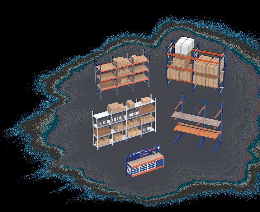
Lagerregal | Schrägbodenregal | Reifenregal
Storage rack | Inclined shelving | Tire rack
Rayonnage mi-lourd | Rayonnage à étagères inclinées |
Rayonnage pour pneus
LR2000
Alle Lagerregale dürfen ausschließlich von Hand be- und entladen werden!
All storage racks may only be loaded and unloaded by hand!
Toutes les rayonnage mi-lourds doivent être chargées et déchargées à la main uniquement !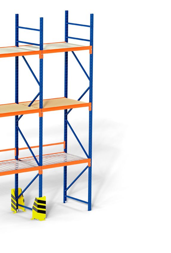
INHALT

     ALLGEMEINES         Begriffserklärung 		                                                       3
                         Übersicht                                                                4–5

DE

EN
     HINWEISE            Allgemeine Hinweise                                                        6
                         Vorbereitung der Montage                                                   7
FR                       Technische Vorschriften                                                  8–9

     STÜCKLISTE          Einzelteile & Montagematerial                                          10 – 11
                         Tiefenstege                                                                 11
                         Erhältliche Regalauflagen                                                   11
                         Übersicht Regalständer                                                      11

     MONTAGE             Montage Regalständer                                                       12
                         Montage Traversen                                                          13
                         Montage Auflagen                                                           14
                         Bodenverankerung Fußplatte                                                 15

     BETRIEBSANLEITUNG   Belastung & Gewichtsverteilung                                             16
                         Prüfung & Kontrolle                                                        16
                         Handhabung                                                                 16
                         Nutzungshinweise                                                           17

     INSPEKTION          Regalinspektion                                                            18

     ZUBEHÖR             Höhenausgleichsblech / Rammschutzpoller / Rammschutzplanke                 19
                         Anfahrschutz in L-Form / U-Form                                            20
                         Magnetband / Lochrückwand / Seitenwand / Steckelemente                     20
                         Distanzstück / Tiefensteg / Werkzeugschränke / Spind / Metallschrank       21
                         Sichtlagerkästen                                                           22

      2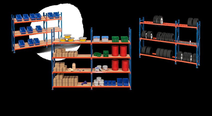
ALLGEMEINES

BEGRIFFSERKLÄRUNG

Feldlast                                                                                                      DE
                                            • Gesamtbelastbarkeit zwischen 2 Regalständern
                                            • Max. Feldlast: 2000 kg
                                                                                                              EN

                                                                                                              FR

           Feldlast

Fachlast

                                            • Gesamtbelastbarkeit pro Traversenebene
                                            • Max. Fachlast: 500 kg pro Ebene

        Fachlast

Punktlast

                                            • Eine vom Ständer erzeugte Last auf das Fundament
                                            • Max. Punktlast je Fußplatte für äußere Ständer: 500 kg
                                            • Max. Punktlast je Fußplatte für innere Ständer: 1000 kg

   Punktlast

                      Belastbarkeit
                      Die Angaben zur Belastbarkeit beziehen sich auf ein Regal mit mind. 2 Feldern
                      und mind. 2 Fachebenen, welche in der Höhe annähernd gleichmäßig eingehängt sind.

     + 49 (0) 7158 9181 500                  info @ topregal.com                www.topregal.com          3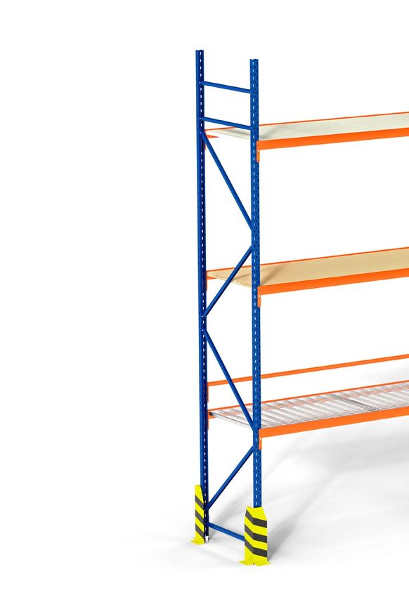
ALLGEMEINES

     ÜBERSICHT                                       Kompletter Ständer

DE

EN    STÄNDER

      Ein kompletter Ständer besteht aus zwei
FR    kaltgewalzten blauen Ständerprofilen,
      sowie den ebenfalls blau lackierten
      Quer- und Diagonalstreben.

      Ständertiefen sind standardmäßig in
      40 cm, 50 cm, 60 cm, 80 cm, 100 cm oder
      120 cm erhältlich.

      Die zur Montage notwendigen Fußplatten,
      Bolzenanker M8 x 55 mm und Muttern
      sind stets inklusive.

      REGALBODEN AUS STAHL

      Stahlboden – 25 mm stark – wird
      direkt auf die Traversen aufgelegt
      und durch die Bauweise der
      Stufentraverse selbstfixiert.

      REGALBODEN AUS HOLZ

      Spanplatte - 25 mm stark - wird direkt
      auf die Traversen aufgelegt und durch die
      Bauweise der Stufentraverse selbstfixiert.

      GITTERROST

      Feuerverzinkte Gitterrostauflage - 25 mm
      stark - wird direkt auf die Traversen aufge-
      legt und durch die Bauweise der
      Stufentraverse selbstfixiert.
      Die Maschenweite beträgt 9,9 x 3,3 cm.

     4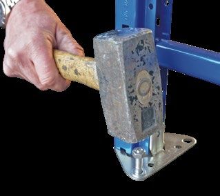
ALLGEMEINES

                                                                                                                                                                             DE
                                                                                       TRAVERSEN
                                                                                                                                                                             EN
                                                                                       Traversen sind die Ladungsträger
                                                                                       eines Lagerregals, auf welche der
                                                                                       Regalboden eingelegt wird. Sie können                                                 FR
                                                                                       in einem Raster von 5 cm mithilfe der
                                                                                       einfachen Steckbauweise individuell
                                                                                       eingehängt werden.

                                                                                       Traversenlängen sind in 110 cm und
                                                                                       220 cm erhältlich.

                                              MODELL
                                            Lagerregal
                                           Typ: LR 2000
                                           Baujahr: 2020

                                             Platzhalter für
                                            die Prüfplakette

                                                                                       BELASTUNGSSCHILD
                                MAXIMALE BELASTUNG
                                              Fachlast:               500kg

                                              Feldlast:             2000kg

                                       Bei gleichmäßig verteilter Last.
                                Montage- und Betriebsanleitung ist zu beachten!

                                 TOPREGAL GmbH, Industriestraße 3, 70794 Filderstadt

                                 07158 - 91 81 500          www.topregal.com

                                                                                       Selbstklebendes
                                                                                       Belastungsschild                         MODELL
                                                                                       mit Angaben zur                        Lagerregal
                                                                                                                             Typ: LR 2000
                                                                                       Tragfähigkeit – es                    Baujahr: 2020

                                                                                       entspricht den Vorgaben
                                                                                       der DGUV: 108-007                       Platzhalter für
                                                                                                                              die Prüfplakette

                                                                                       (ehemals BGR 234).

                                                                                       Das Belastungsschild       MAXIMALE BELASTUNG

                                                                                       wird immer mitgeliefert                  Fachlast:               500kg

                                                                                                                                Feldlast:             2000kg
                                                                                       und muss gut sichtbar             Bei gleichmäßig verteilter Last.

                                                                                       am Regal angebracht
                                                                                                                  Montage- und Betriebsanleitung ist zu beachten!

                                                                                                                   TOPREGAL GmbH, Industriestraße 3, 70794 Filderstadt

                                                                                       werden.                     07158 - 91 81 500          www.topregal.com

                                                                                       SICHERHEITSRELEVANTES ZUBEHÖR

                                                                                       Anfahrschutz in L- und U-Form, sowie
                                                                                       Rammschutzplanken zur Vermeidung
                                                                                       eventueller Schäden am Regalständer.
                                                                                       Erhältlich in 40 cm und 80 cm Höhe.

+ 49 (0) 7158 9181 500   info @ topregal.com                                              www.topregal.com                                                               5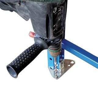
HINWEISE

     ALLGEMEINE HINWEISE
     Gefahren vorbeugen
DE
     Das von Ihnen erworbene Regal ist dem heutigen Stand der Technik entsprechend hergestellt und entspricht den geltenden
     Vorschriften und Regeln. Trotz alledem kann es eine Gefahr für Personen und Sachwerte darstellen, wenn:
EN
     • das Regal nicht ordnungsgemäß aufgebaut, unsachgemäß verändert oder umgebaut wird.
     • kein Original-Zubehör verwendet wird.
FR   • die Sicherheitsbestimmungen nicht beachtet werden.

     Daher muss jede Person, welche die Montage durchführt, die Sicherheitsbestimmungen lesen und befolgen, gegebenenfalls
     lassen Sie sich dies durch eine Unterschrift bestätigen.

     Unfallverhütungsvorschriften
     Es gelten alle einschlägigen Unfallverhütungsvorschriften:

     • Allgemein anerkannte sicherheitstechnische Regeln
     • Länderspezifische Bestimmungen
     • Richtlinien für Lagereinrichtungen und Geräte des jeweiligen Landes

     Bitte beachten
     Vor der Montage, Inbetriebnahme oder Nutzung sind die in dieser Anleitung enthaltenen Hinweise zwingend zu beachten,
     um Gefahren vermeiden zu können. Falls Sie fachliche Unterstützung benötigen, setzen Sie sich mit uns in Verbindung.

     Um Personen und Sachschäden zu vermeiden, beachten Sie bitte:

     •   die Richtlinien der Lagereinrichtungen und -geräte DGUV 108-007.
     •   die einschlägigen Arbeitsstättenrichtlinien und -verordnungen.
     •   die Hinweise Ihres Sicherheitsbeauftragten.
     •   die baulichen Gegebenheiten und Verordnungen, insbesondere auch die Beschaffenheit und Tragfähigkeit des Fußbodens.
     •   dass sich die Einrichtungen in einwandfreiem Zustand befinden.
         Der Austausch beschädigter oder deformierter Bauteile ist sofort zwingend notwendig. Im Zweifelsfalle unterbrechen Sie
         die Montage bzw. Nutzung, sichern den Aufstellbereich und verständigen Ihren Sicherheitsbeauftragten.
     •   dass die Beladung erst nach Abschluss aller Montagearbeiten vorgenommen werden darf.
     •   dass die Personen des Auf- und Umbaus entsprechend den UVV-Bauarbeiten (VBG 37 §12) gegen Absturz zu sichern sind.
     •   dass beim Auf- und Umbau Schutzkleidung wie Helm, Handschuhe, Sicherheitsschuhe etc. zu tragen sind.
     •   dass die Regale wirksam gegen das Anfahren von Staplern oder anderen Fahrzeugen zu schützen sind.

         6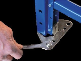
HINWEISE

VORBEREITUNG DER MONTAGE
Alle original TOPREGAL Bauteile, die der Stabilisierung der Lagereinrichtung dienen, sind uneingeschränkt anzubringen.
Darunter fallen vor allem Rahmenbauteile, Feldverbände, Diagonalstreben, Traversen, Bodenverdübelungen, Schrauben/           DE
Befestigungselemente sowie Sicherungsstifte. Generell ist bei der Montage darauf zu achten, dass die Schrauben
nicht überdreht werden. Die Schrauben sind handfest zu montieren und später mit passendem Werkzeug, wie z. B.
Akkuschrauber oder Schraubenschlüssel, fest nachzuziehen.                                                                    EN

Planung                                                                                                                      FR
Vor dem Aufstellen der Regale wird die dafür vorgesehene Fläche ausgemessen und die Stellung der Regalzeilen
aufgezeichnet. Achten Sie darauf, dass die Regalreihen in gerader Flucht stehen. Bandmaß und Schlagschnur sind dafür
am Besten geeignet.

Prüfung von Fußboden und Bodentoleranzen
Vor dem Aufstellen von Regaleinrichtungen prüfen Sie:

• ob die Tragfähigkeit des Fußbodens geeignet ist, um die vorgesehenen Belastungen sicher aufzunehmen.
  Im Zweifelsfalle fragen Sie einen Fachmann und lassen die Tragfähigkeiten bestimmen.
• Die Verantwortung über die Richtigkeit der Angaben trägt der Bauherr.

                    Aufbau
                    Regale dürfen nur unter Beachtung der von uns mitgelieferten Aufbau- und Betriebsanleitungen
                    durch hierin besonders unterwiesene Personen aufgestellt und umgebaut werden. Der Umbau
                    von Regalen darf nur in unbeladenem Zustand erfolgen.

       + 49 (0) 7158 9181 500                info @ topregal.com                 www.topregal.com                        7
HINWEISE

     TECHNISCHE VORSCHRIFTEN

DE
     Grundlegender Aufbau
EN   Alle Belastungsangaben beziehen sich auf eine Regalzeile mit mindestens 2 Feldern. In jedes Feld müssen mindestens zwei
     Fächer (4 Traversen) eingehängt werden.
     Die Fachhöhen sind für alle Fächer annähernd gleich zu halten. Weicht die Fachhöhe von Feld zu Feld um über
FR   10 % ab, verringert sich die maximale Feldlast.

     Die Ständer werden durch Schraubverbindungen mit der Fußplatte verbunden und dann im Untergrund fixiert.
     Die Traversen werden durch einfache Steckbauweise mit Sicherungsstift angebracht.

     Anfahrschutz
     Eckbereiche und Durchfahrten sind durch einen nicht mit dem Regal verbundenen Anfahrschutz mit gelb-schwarzer
     Gefahrenkennzeichnung zu schützen. (s. DGUV: 108-007)

     Sicherheitsabstände
     Bei Montage ist der genaue Standort des Regals vorher auf dem Boden zu markieren. Hierbei ist der notwendige
     Sicherheitsabstand zu Bauwerksteilen (z. B. Wand, Säule) und Gängen zu beachten. (s. DGUV: 108-007)

      8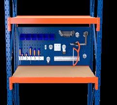
HINWEISE

                                                                                                                          DE
Kennzeichnung
Eine Kennzeichnung durch ein Belastungsschild ist vorgeschrieben. Diese sind im Lieferumfang enthalten.                   EN

                                                                                                                          FR

Lotrechtes Aufstellen
Das Regal ist lotrecht auszurichten. Abweichungen der Regalstützen von der Lotrechten in Längs- und Tiefenrichtung
der Regale dürfen nicht mehr als 1/200 der Regalstützhöhen betragen. Um Bodenunebenheiten auszugleichen, können
Höhenausgleichsbleche verwendet werden. Die einzelnen Ständer müssen innerhalb einer Regalreihe in einer Flucht stehen.

Wenn die Höhe des obersten Regalbodens über der Standfläche mehr als das 5-fache der Regaltiefe beträgt, muss eine
Sicherung gegen Kippen vorgenommen werden, z. B. durch eine Bodenverankerung. Hierfür geeignete Bolzenanker sind im
Lieferumfang enthalten. Erst nach abgeschlossener Montage dürfen die Regale beladen werden.

  Beispiel: Regalstützhöhe 4 Meter
                                                                                             max. Abweichung

   Regalhöhe h
                   =   max. Abweichung
       200
     400 cm
                   =   2 cm
       200                                           h

  Die maximale Abweichung in Längs- und
  Querrichtung darf, bei diesem Beispiel, somit
  höchstens 2 cm betragen.

       + 49 (0) 7158 9181 500                info @ topregal.com               www.topregal.com                    9
STÜCKLISTE

     A Ständerprofil    E Traverse

DE

EN

FR

     B Querstrebe       F Sicherungsstift

     C Diagonalstrebe   G Inbusschraube M5 x 35 mm

     D Fußplatte        H Mutter M5

     10
STÜCKLISTE
I Regalboden J Bolzenanker
DE
EN
FR
TIEFENSTEGE
• Tiefenstege kommen in den Tiefen 100 cm und 120 cm zum Einsatz
• 120 cm tiefe Regale benötigen: bei 110 cm langen Regalauflagen
1 Tiefensteg; bei 220 cm langen Auflagen 2 Tiefenstege.
• Tiefenstege bei 110 cm mittig einlegen, bei 220 cm jeweils 60 cm
Abstand vom Regalständer (siehe Fotos).
ERHÄLTLICHE REGALAUFLAGEN
Holzboden Stahlboden Gitterrost Multiplex Reifen / ohne Boden Schrägboden
Belastung pro Ebene 500 kg 500 kg* 500 kg 500 kg 400 kg 300 kg
Länge 110 / 220 cm 110 / 220 cm 110 / 220 cm 110 / 220 cm 110 / 220 cm 110 / 220 cm
40, 50, 60, 80,
Tiefe 60, 80,120 cm 60, 80,120 cm 60, 80 cm 40, 50, 60, 80 cm 40, 60, 80 cm
100, 120 cm
*Stoßlasten beim Beladen von Hand sind zu vermeiden, da dies zu Beschädigungen am Stahlboden führen kann
ÜBERSICHT REGALSTÄNDER
Höhe 2m 2,5 m 3m 3,5 m 4m
Tiefe Tiefe 40, 50, 60, 80, 100, 120 cm
Feldlast 2000 kg 2000 kg 2000 kg 2000 kg 2000 kg
Anzahl Querstreben 3 2 2 3 3
Anzahl Diagonalstreben 2 3 4 4 5
Farbe RAL 5005 RAL 5005 RAL 5005 RAL 5005 RAL 5005
+ 49 (0) 7158 9181 500 info @ topregal.com www.topregal.com 11MONTAGE
1 I STÄNDER
B
DE
A
EN
FR
C
G
H
D
1.1 I Streben B und C in Ständerprofil A schieben und mit Schrauben G und Muttern H festschrauben.
1.2 I Fußteil D auf das Ständerprofil stecken und mit Schrauben G und Muttern H montieren.
12MONTAGE
2 I TRAVERSEN
DE
EN
FR
F
E
2.1 I Traversen E am Ständer einhängen und mit Sicherungsstift F sichern.
+ 49 (0) 7158 9181 500 info @ topregal.com www.topregal.com 13MONTAGE
3 I AUFLAGEN
DE
EN I
FR
Auflage
Traverse
3.1 I Einlegen der Regalauflage in die Stufentraverse (selbstfixierend).
14MONTAGE
BODENVERANKERUNG FUSSPLATTE
Benötigte Einzelteile: Vormontiertes Regal, Bolzenanker J DE
• Löcher in den Boden bohren (ca. 80 mm tief) mit einem Bohrer von 8 mm Durchmesser. EN
• Löcher staubfrei absaugen.
• Bolzenanker in das Bohrloch schlagen.
• Die Mutter mit einem Gabelschlüssel o. ä. fest anziehen. FR
+ 49 (0) 7158 9181 500 info @ topregal.com www.topregal.com 15BETRIEBSANLEITUNG
BELASTUNG & GEWICHTSVERTEILUNG
• Die angegebene, gleichmäßig verteilte Belastung für Fach und Feld darf nicht überschritten werden.
• Es ist darauf zu achten, dass das Lagergut gleichmäßig auf die Regalträger verteilt wird.
DE • Die Lasteinheiten dürfen nicht über die Auflageträger geschoben oder stoßartig darauf abgesetzt werden.
• Regale dürfen nur nach unseren Angaben belastet werden. Die Beladung der Regale muss gleichmäßig sein,
da die statische Auslegung auf der Annahme einer gleichmäßig verteilten Flächenbelastung beruht.
EN Punktförmige Stoßlasten und Schiebelasten sind demzufolge zu vermeiden.
FR
PRÜFUNG & KONTROLLE
• Wurde das Regal entsprechend der Montageanleitung aufgebaut?
• Sind Schäden an Teilen der Konstruktion vorhanden?
• Sind Schäden durch Stoßeinwirkung oder Überlastung an Trägern vorhanden?
• Stehen die Regalstützen lotrecht?
• Sind Risse in Schweißnähten oder im Grundmaterial vorhanden?
• Wie ist der Zustand und die Wirksamkeit der Sicherungen?
• Wie ist der Zustand des Gebäudebodens?
• Ist die Last gleichmäßig verteilt, sind die Regale zu schwer beladen?
• Wie ist die Position der Ladeeinheit auf dem Regal?
• Ist die Stabilität der Ladeeinheiten gegeben?
HANDHABUNG
• Die Regale sind grundsätzlich gemäß den Angaben in der Montageanleitung zu montieren. Eigenmächtige
Veränderungen an den Regalen sind in jedweder Form unzulässig.
• Es sind an allen Regalreihen entsprechende Belastungsaufkleber anzubringen. Diese Betriebsanleitung muss auch
den Lagerarbeitern zugänglich gemacht werden.
• Örtliche Veränderung der Regale oder Umstecken von Traversen dürfen nur im entladenen Zustand vorgenommen werden.
• Regale dürfen nicht von Personen betreten werden.
• Beschädigte und verformte Regalteile müssen umgehend ausgetauscht werden, da die Belastbarkeit nur in einem
unbeschädigten Zustand garantiert wird. Daher dürfen beschädigte Komponenten nicht weiter genutzt werden.
• Die Summe aller Fachlasten in einem Feld darf die maximale Feldlast nicht überschreiten.
• Das Anfahren der Regalständer mit Flurfördermitteln (z. B. Gabelstapler) kann zu einer massiven Beeinträchtigung der
Belastbarkeit des Regals führen und ist daher unter allen Umständen zu vermeiden.
• Generell gelten zusätzlich alle Unfallverhütungsvorschriften und die gesetzlichen Bestimmungen für Arbeitssicherheit.
16BETRIEBSANLEITUNG
NUTZUNGSHINWEISE
Grundlegendes DE
Regalständer und Regalfächer, insbesondere Fachböden, dürfen nicht von Personen betreten werden.
EN
Bedienung der Regale FR
Beschädigte und verformte Bauteile einer Regalanlage müssen umgehend ausgetauscht werden, da die Belastbarkeit nur in
einwandfreiem Zustand garantiert werden kann. Die von uns angegebenen Fach- und Feldlasten gelten nur bei gleichmäßig
verteilter Last.
Zulässige Tragfähigkeiten
• Fachlast = Belastung je Regalebene.
• Feldlast = gesamte Feldlast zwischen 2 Regalständern = Fachlast x Anzahl der übereinanderliegenden Regalebenen.
• Das Lagergut, das direkt auf dem Hallenboden steht, wird nicht berücksichtigt.
• Die Summe aller Fachlasten darf die maximale Feldlast nicht überschreiten.
• Fachlasten sind gleichmäßig verteilte Lasten.
Hinweis für Stapler / Flurförderzeuge
Es ist zwingend darauf zu achten, dass Regale nicht von Staplern / Hubwägen oder sonstigen Flurförderzeugen angefahren
werden. Geeignete Schutzvorrichtungen hierfür finden Sie auf Seite 19 – 20.
Be- und Entladung
Alle Weitspannregale dürfen ausschließlich von Hand be- und entladen werden!
Eine Beladung durch Ameisen, Gabelstapler oder ähnliche Gerätschaften ist strikt untersagt!
Belastbarkeit
Die Angaben zur Belastbarkeit beziehen sich auf ein Regal mit mind. 2 Feldern und mind.
2 Fachebenen, welche in der Höhe annähernd gleichmäßig eingehängt sind.
+ 49 (0) 7158 9181 500 info @ topregal.com www.topregal.com 17INSPEKTION
Die europäische Richtlinie DIN EN 15635 weist auf die Verantwortung des Betreibers hin, die Regale in ordnungsgemäßem
DE Zustand zu halten. Hierzu müssen an den Regalen in regelmäßigen Abständen Sichtkontrollen sowie Experteninspektionen
durchgeführt werden, um die Sicherheit gewährleisten zu können. Hierbei sind u. A. folgende Aspekte zu prüfen:
EN • Stehen die Regalstützen lotrecht?
• Sind Risse in Schweißnähten oder im Grundmaterial vorhanden?
• Wie ist der Zustand und die Wirksamkeit der Sicherungen?
FR • Wie ist der Zustand des Gebäudebodens?
• Wie ist die Position der Ladeeinheit auf dem Regal?
• Sind Belastungs- und Informationshinweise vorhanden und aktuell?
• Ist die Stabilität der Ladeeinheiten gegeben?
Die durchgeführten Prüfungen, Mängel und deren Beseitigung sind schriftlich zu dokumentieren. Diese Dokumentation ist
mindestens bis zur nächsten regelmäßigen Prüfung aufzubewahren. Es empfiehlt sich jedoch, die Dokumentation über die
gesamte Lebensdauer des Regals aufzubewahren. (vgl. BGI/GUV-I 5166)
Zur Inspektion befähigte Personen
Befähigt ist, wer Fachkenntnisse aus zeitnaher beruflicher Tätigkeit im Umfeld des Prüfgegenstandes und angemessene
Weiterbildung vorweisen kann. Dies sind z. B. Monteure des Herstellers oder entsprechend qualifiziertes Personal des
Betreibers.
Sichtkontrolle
• Sichtkontrollen sind grundlegend wöchentlich durchzuführen.
• Sichtkontrollen können durch eine interne, befähigte Person durchgeführt werden.
• Der Prüfumfang kann auf die Teile des Regals reduziert werden, bei dem Mängel seit der letzten Prüfung zu erwarten sind.
Experteninspektion
• Experteninspektionen sind mindestens alle 12 Monate durchzuführen.
• Die umfassende Experteninspektion sollte von einer fachkundigen meist externen, Person durchgeführt werden und ein
ganzheitliches Prüfprotokoll erstellt werden.
Sie haben Fragen zur Regalprüfung oder möchten, dass unsere zertifizierten Regalprüfer
die Inspektion für Sie durchführen?
Sprechen Sie uns darauf an! Tel. 07158-91 81 500
18ZUBEHÖR
HÖHENAUSGLEICHSBLECH ART.-NR. 2375
• Unterlegbleche zum Ausgleich von Bodenunebenheiten zur
Verhinderung von Schrägstellungen der Regale DE
• Unterlegbleche sind bis max. 2 cm beliebig aufeinander stapelbar
EN
FR
RAMMSCHUTZPLANKE 40 CM ART.-NR. 11757, 11758, 11759, 5434, 11760
• Materialstärke: 4 mm
• Höhe: 40 cm
• Längen: 93 cm / 123 cm / 193 cm / 253 cm / 360 cm
• Gelb lackiert mit schwarzen Signalstreifen
• Schutz vor versehentlichem Anfahren, z. B. mit Flurförderzeugen
• Geprüft nach DGUV 108-007
Montage: Rammschutzplanke mithilfe der mitgelieferten 8 Bolzenanker (jeweils 4 pro Seite) im Boden verankern.
RAMMSCHUTZPLANKE 80 CM ART.-NR. 11761, 11762, 11763, 11764, 11765
• Materialstärke: 4 mm
• Höhe: 80 cm
• Längen: 93 cm / 123 cm / 193 cm / 253 cm / 360 cm
• Gelb lackiert mit schwarzen Signalstreifen
• Schutz vor versehentlichem Anfahren, z. B. mit Flurförderzeugen
• Geprüft nach DGUV 108-007
Montage: Rammschutzplanke mithilfe der mitgelieferten 8 Bolzenanker (jeweils 4 pro Seite) im Boden verankern.
RAMMSCHUTZPOLLER ART.-NR. 10136
• Höhe: 120 cm / Gewicht 19 kg
• Durchmesser 16 cm
• Fußplatte mit 25 x 25 cm
• Gelb lackiert mit schwarzen Signalstreifen
• Schutz vor versehentlichem Anfahren, z. B. mit Flurförderzeugen
Montage: Rammschutzpoller mithilfe der mitgelieferten 4 Bolzenanker im Boden verankern.
+ 49 (0) 7158 9181 500 info @ topregal.com www.topregal.com 19ZUBEHÖR
ANFAHRSCHUTZ IN L/U-FORM ART.-NR. L-FORM = 4749, 9870 / U-FORM = 4748, 9668
• Höhen: 40 cm / 80 cm inkl. 4 Bolzenanker
DE • Gelb lackiert mit schwarzen Signalstreifen
• Eck-Rammschutz, um die äußeren Ständer vor versehentlichem
Anfahren durch Hubhebemittel, wie z. B. Gabelstapler,
EN Ameisen etc. zu schützen
• Geprüft nach DGUV 108-007
FR
Montage: Anfahrschutz mithilfe der mitgelieferten 4 Bolzenanker im Boden verankern.
MAGNETBAND ART.-NR. 9590, 9591
• Magnetband zum Beschriften von Regalen oder z. B. auf
Autokarosserien, Maschinen o. Ä.
• Maße: L 1000 cm / B 5 cm oder 10 cm / T 0,15 cm
• Wiederverwendbar
• Leichtes Zuschneiden mit handelsüblichen Scheren
LOCHRÜCKWAND / SEITENWAND ART.-NR. 18344, 18345, 27630, 27631
• Werden in eine normale Regalzeile oder die Seitenwand eines
Lagerregals angebracht
• Die Lochabstände sind kompatibel mit gängigen Anwendungen
• Maße der Lagerregal Lochwand: 110 cm / 220 cm lang, 50 cm hoch
• Maße der Seitenwand: 100 cm hoch, 60 cm / 80 cm tief
STECKELEMENTE ART.-NR. 29214, 29215, 29216
• Werkzeughalter / Maschinenhaltersets aus verzinktem Stahl für
Zubehörartikel „Seitenwand / Lochwand für Lagerregal / MFR“
• Optimal für die Lagerung von jeglichem Werkzeug zum Einhaken wie z. B.
Zangen, Maulschlüssel, Akkuschrauber, Kabel, Rohre, Sägen, etc.
• Die einzelne Elemente lassen sich durch ein einfaches Stecksystem ohne
Montage an unsere Seitenwände / Lochwände anbringen
20ZUBEHÖR
DISTANZSTÜCK ART.-NR. 5805
• Distanzstück zur Parallelstellung von Lagerregalreihen
• Kann auch verwendet werden, um das Lagerregal an der Wand DE
zu befestigen
• Länge: 20 cm
• Farbe TOPREGAL-Blau (entspricht in etwa RAL 5010) EN
• Bei Ständerhöhe < 2,5 m empfehlen wir 2 Distanzstücke pro Ständer
• Bei Ständerhöhe ab 3 m empfehlen wir 3 Distanzstücke pro Ständer
FR
Montage: Distanzstück wird mit Schraubverbindungen an den Ständern montiert.
TIEFENSTEG ART.-NR. 9824
• Tiefensteg für Lagerregale mit 120 cm Tiefe
- 1 Tiefensteg bei 110 cm Regalböden
- 2 Tiefenstege bei 220 cm Regalböden
• Länge: 115 cm
• Farbe TOPREGAL-Orange (entspricht etwa RAL 2004)
• Erhöht die Traglast des Regalbodens bei einer Tiefe von 120 cm
• Tiefensteg ist im Lieferumfang der Komplettangebote bereits inklusive
WERKZEUGSCHRÄNKE ART.-NR. 18569, 18570, 18571, 18572
• Erhältlich in den Tiefen 60 cm und 80 cm
• Farbe TOPREGAL-Blau (entspricht in etwa RAL 5010)
• Höhe: 57 cm / Breite: 54 cm
• Schränke werden nur eingelegt, keine Montage notwendig,
selbstfixierend
• Ausführungen mit abschließbarer Tür oder Schubladen erhältlich
SPIND / GROSSER METALSCHRANK ART.-NR. 85447, 85448, 85449, 85450
• Spind / Großer Metallschrank, abschließbar
Großer
Metallschrank • Fahrbar und stationär verfügbar
• 60 cm & 80 cm Tiefe
Spind
• 176,5 cm Hoch, 110 cm Breit
• Metallschrank: Max. 60 kg pro Boden
• Spind: Max. 40 kg pro Boden
+ 49 (0) 7158 9181 500 info @ topregal.com www.topregal.com 21ZUBEHÖR
FALTBARER SICHTLAGERKASTEN 8,5 L ART.-NR. 87077, 87389, 87390
• Breite: 21,6 cm / Höhe: 17,5 cm / Länge: 33,6 cm
DE • Es können Gewichte bis zu 20 kg pro Sichtlagerkasten gelagert
werden
EN
FR
FALTBARER SICHTLAGERKASTEN 15 L ART.-NR. 87078, 87391, 87392
• Breite: 27 cm / Höhe: 20 cm / Länge: 42 cm
• Es können Gewichte bis zu 20 kg pro Sichtlagerkasten gelagert
werden
FALTBARER SICHTLAGERKASTEN 30 L ART.-NR. 87079, 87393, 87394
• Breite: 30,3 cm / Höhe: 27,5 cm / Länge: 50 cm
• Es können Gewichte bis zu 28 kg pro Sichtlagerkasten gelagert
werden
SICHTLAGERKASTEN SET JE 5 x 8,5 L, 15 L, 30 L ART.-NR. 94856
• 8,5 l = Breite: 21,6 cm / Höhe: 17,5 cm / Länge: 33,6 cm
• 15 l = Breite: 27 cm / Höhe: 20 cm / Länge: 42 cm
• 30 l = Breite: 30,3 cm / Höhe: 27,5 cm / Länge: 50 cm
• Es können Gewichte bis zu 20 kg (8,5 l und 15 l) bzw. 28 kg (30 l)
pro Sichtlagerkasten gelagert werde
5x 5x 5x
SICHTLAGERKASTEN SET JE 10 x 8,5 L, 15 L, 30 L ART.-NR. 94857
• 8,5 l = Breite: 21,6 cm / Höhe: 17,5 cm / Länge: 33,6 cm
• 15 l = Breite: 27 cm / Höhe: 20 cm / Länge: 42 cm
• 30 l = Breite: 30,3 cm / Höhe: 27,5 cm / Länge: 50 cm
• Es können Gewichte bis zu 20 kg (8,5 l und 15 l) bzw. 28 kg (30 l)
pro Sichtlagerkasten gelagert werden
10x 10x 10x
22BESTELLSCHEIN
AUSFÜLLEN
& FAXEN
AN FAX 07158 - 91 81 549
DE
EN
FR
ODER ALS SCAN PER EMAIL
AN INFO@TOPREGAL.COM SENDEN!
Art. Nr. Bezeichnung Anzahl
WIR BITTEN UM BESTELLUNG / LIEFERUNG PER VORKASSE PER RECHNUNG
(ABZÜGL. 2% SKONTO) (BIS 10 TAGE NACH ERHALT DER WARE)
WIR BITTEN UM EIN ANGEBOT ODER EINEN RÜCKRUF
RECHNUNGSADRESSE LIEFERADRESSE
(FALLS ABWEICHEND)
Firma / Kunde Firma / Kunde
Ansprechpartner Ansprechpartner vor Ort
Straße / Hausnummer Straße / Hausnummer
PLZ / Ort PLZ / Ort
Telefon Telefon
E-Mail E-Mail
Unterschrift
+ 49 (0) 7158 9181 500 info @ topregal.com www.topregal.com 23CONTENTS
GENERAL INFORMATION Explanation of terms 25
Overview 26 – 27
DE
EN
NOTE General information 28
Assembly preparation 29
FR Technical regulations 30– 31
PARTS LIST Individual parts & assembly material 32 – 33
Support bars 33
Available shelves 33
Overview rack uprights 33
ASSEMBLY Rack upright assembly 34
Beam assembly 35
Shelf assembly 36
Ground anchoring foot plate 37
INSTRUCTION MANUAL Load & weight distribution 38
Testing & Control 38
Handling 38
Instructions for use 39
INSPECTION Rack inspection 40
ACCESSORIES Height-adjustment plate / crash protection bollard/rail 41
L-/U-profile rack protection 42
Magnetic tape / perforated back/side panel / plug-in elements 42
Spacers / support bar / tool cabinets / locker / metal cabinet 43
Pick bins / reusable containers 44
24GENERAL INFORMATION
EXPLANATION OF TERMS
Unit load DE
• Total load capacity between 2 horizontal bars
• Max. unit load capacity: 2000 kg
EN
FR
Unit load capathity
Compartment load
• Total load capacity per beam level
• Max. compartment load: 500 kg per level
Shelf capacity
Point load
• A load on the foundation generated by the upright
• Max. point load per foot plate for outer uprights: 500 kg
• Max. point load per foot plate for inner uprights: 1000 kg
Point load capathity
Load capacity
The information on load capacity refers to a rack with at least 2 units and at least 2
compartment levels, which are attached approximately evenly in height.
+ 44 (0) 20 789 415 16 info @ topregal.com www.topregal.com 25GENERAL INFORMATION
OVERVIEW Complete upright
DE
UPRIGHT
EN
A complete upright consists of two cold-
rolled blue upright profiles and cross and
FR diagonal struts, which are also painted blue.
Available standard upright depths are
40 cm, 50 cm, 60 cm, 80 cm, 100 cm and
120 cm.
The foot plates, M8 x 55 mm bolt anchors
and nuts required for assembly are always
included.
STEEL SHELF
Steel shelf – 25 mm thick – placed
directly onto the beams and self-fixing
due to the design of the stepped beam.
WOODEN SHELF
Chipboard – 25 mm thick – placed
directly onto the beams and self-fixing
due to the design of the stepped beam.
GALVANISED MESH DECK
Galvanised mesh shelf – 25 mm thick –
placed directly onto the beams and self-
fixing due to the design of the stepped
beam.
The mesh size is 9.9 x 3.3 cm.
26GENERAL INFORMATION
DE
BEAMS EN
Beams are the load carriers of a storage
rack on which the shelf is placed. They can FR
be attached individually in 5 cm increments
using the simple plug-in construction.
Beam lengths are available in 110 cm and
220 cm.
MODELL
Lagerregal
Typ: LR 2000
Baujahr: 2020
Platzhalter für
die Prüfplakette
LOAD CAPACITY LABEL
MAXIMALE BELASTUNG
Fachlast: 500kg
Feldlast: 2000kg
Bei gleichmäßig verteilter Last.
Montage- und Betriebsanleitung ist zu beachten!
TOPREGAL GmbH, Industriestraße 3, 70794 Filderstadt
07158 - 91 81 500 www.topregal.com
Self-adhesive load
capacity label with MODELL
information on the load Lagerregal
Typ: LR 2000
capacity – it corresponds Baujahr: 2020
to the specifications of
the German regulation Platzhalter für
die Prüfplakette
DGUV 108-007
(formerly BGR 234) and
is additionally displaying MAXIMALE BELASTUNG
a inspection sticker. Fachlast: 500kg
Feldlast: 2000kg
Bei gleichmäßig verteilter Last.
The load capacity label
Montage- und Betriebsanleitung ist zu beachten!
TOPREGAL GmbH, Industriestraße 3, 70794 Filderstadt
is always supplied and 07158 - 91 81 500 www.topregal.com
must be attached to the
rack in a clearly visible
place.
SAFETY & PROTECTION EQUIPMENT
L- and U-profile collision protection, as
well as crash protection rails to prevent
possible damage to the rack upright.
Available in 40 cm and 80 cm height.
+ 44 (0) 20 789 415 16 info @ topregal.com www.topregal.com 27NOTE
GENERAL INFORMATION
Prevent dangers
DE
The TOPREGAL product you have purchased is manufactured in accordance with the current state of the art and complies with
the applicable regulations and rules. Despite all this, it can pose a danger to persons and property if:
EN
• the rack is not properly assembled, improperly modified or converted.
• accessories used are not original ones.
FR • the safety regulations are not observed.
Therefore, every person involved in the assembly must read and follow the safety regulations and, if necessary, you should have
them confirm this with a signature.
Accident prevention regulations
All relevant accident prevention regulations apply:
• Generally accepted safety regulations
• Country-specific provisions
• Guidelines for storage facilities and equipment of the respective country
Please note
Before assembly, commissioning or use, the information contained in these instructions must be observed in order to avoid
hazards. If you need technical support, please contact us.
In order to avoid personal injury and damage to property, please observe the following:
• the German DGUV 108-007 warehouse facility and equipment guidelines.
• the relevant workplace directives and regulations.
• the information from your safety officer.
• the structural conditions and regulations, in particular the condition and load-bearing capacity of the floor.
• And ensure that the facilities are in good order and condition.
Damaged or deformed components must be replaced immediately. If in doubt, stop assembly or use, secure the
installation area and inform your safety officer.
• that loading may only be carried out after all assembly work has been completed.
• that the persons carrying out the assembly and conversion work are to be secured against falling in accordance with the
UVV construction work (German VBG 37 §12).
• protective clothing such as helmets, gloves, safety shoes, etc. must be worn during assembly and conversion.
• that the racks must be effectively protected against impact from forklifts or other vehicles.
28NOTE
ASSEMBLY PREPARATION
All original TOPREGAL components used to stabilise the warehouse equipment must be installed without exception. These
include in particular frame components, unit assemblies, diagonal struts, beams, floor anchors, screws/fastening elements DE
and safety pins. During assembly one should ensure that the screws are not over-tightened. The screws must be hand-
tightened and tightened later using suitable tools such as a cordless drill or a wrench.
EN
Planning FR
Before the racks are assembled, the area intended for them is measured and the position of the rows of shelves is
recorded. Ensure that the rows of racks are aligned. Tape measure and chalk line are best suited for this.
Testing of floor and floor tolerances
Before setting up rack systems, check the following:
• whether the load-bearing capacity of the floor is suitable for safely withstanding the intended loads. If in doubt, consult
a specialist and have the load capacities determined.
• The responsibility for the correctness of the information lies with the client.
Assembly
Racks may only be set up and converted by specially instructed persons in compliance with the
assembly and operating instructions supplied by us. Racks may only be converted when they are
not loaded.
+ 44 (0) 20 789 415 16 info @ topregal.com www.topregal.com 29NOTE
TECHNICAL REGULATIONS
DE
Basic structure
EN All load specifications refer to a rack row with at least 2 units. At least two compartments (4 beams) must be attached to each unit.
The compartment heights must be kept approximately the same for all compartments. If the compartment height differs
from unit to unit by more than 10 %, the maximum unit load capacity is reduced.
FR
The uprights are connected to the foot plate by screw connections and then fixed to the floor.
The beams are attached by simple plug-in construction with safety pin.
Collision protection
Corner areas and passages must be protected by collision protection with a yellow/black hazard label which is not
connected to the rack. (see DGUV: 108-007)
Safety distances
During assembly, the exact location of the rack must be marked on the floor beforehand. The necessary safety distance to
building components (e.g. wall, column) and corridors must be observed. (see DGUV: 108-007)
30NOTE
DE
Labelling
Labelling using a load capacity label is compulsory. These labels are included in the delivery volume. EN
FR
Plumb installation
The rack must be aligned plumb. Deviations of the rack uprights from the plumb line in longitudinal and depth direction
of the racks must not exceed 1/200 of the rack upright height. Levelling plates can be used to compensate for uneven
floors. The individual uprights within a row of racks must be aligned.
If the height of the top shelf above the floor is more than 5 times the rack depth, it must be secured against tipping, e.g.
by anchoring to the floor. Suitable bolt anchors are included in the delivery volume. The shelves may only be loaded after
assembly has been completed.
Example: Rack upright height 4 metres
max. deviation
Shelf height h
= max. deviation
200
400 cm
= 2 cm
200 h
In this example, the maximum deviation
in longitudinal and transverse direction must
therefore not exceed 2 cm.
+ 44 (0) 20 789 415 16 info @ topregal.com www.topregal.com 31PARTS LIST
A Upright profile E beam
DE
EN
FR
B Cross strut F safety pin
C Diagonal strut G M5 x 35 mm Allen screw
D Foot plate H M5 nut
32PARTS LIST
I Shelf J Bolt anchor
DE
EN
FR
SUPPORT BARS
• Support bars are used on racks with depths of 100 cm and 120 cm
• 120 cm-deep shelves need: 1 support bar for shelf lengths of 110 cm;
2 support bars for shelf lengths of 220 cm.
• For lengths of 110 cm, insert the support bar in the middle; for lengths
of 220 cm, insert the support bars 60 cm from the rack uprights (see
photos).
AVAILABLE SHELVES
Wooden shelf Steel shelf Galvanised mesh deck Multiplex Tyres / without shelf Kanban shelf
Load per level 500 kg 500 kg* 500 kg 500 kg 400 kg 300 kg
Length 110 / 220 cm 110 / 220 cm 110 / 220 cm 110 / 220 cm 110 / 220 cm 110 / 220 cm
40, 50, 60, 80, 100,
Depth 60, 80, 120 cm 60, 80, 120 cm 60, 80 cm 40, 50, 60, 80 cm 40, 60, 80 cm
120 cm
*Avoid shock loads when loading by hand as this can damage the steel shelf
OVERVIEW RACK UPRIGHTS
Height 2m 2.5 m 3m 3.5 m 4m
Depth Depth 40, 50, 60, 80, 100, 120 cm
Unit load 2000 kg 2000 kg 2000 kg 2000 kg 2000 kg
Number of cross struts 3 2 2 3 3
Number of diagonal struts 2 3 4 4 5
Colour RAL 5005 RAL 5005 RAL 5005 RAL 5005 RAL 5005
+ 44 (0) 20 789 415 16 info @ topregal.com www.topregal.com 33ASSEMBLY
1 I UPRIGHT
B
DE
A
EN
FR
C
G
H
D
1.1 I Slide struts B and C into the upright profile A and tighten using bolts G and nuts H.
1.2 I Place the foot part D on the upright profile and secure using screws G and nuts H.
34ASSEMBLY
2 I BEAMS
DE
EN
FR
F
E
2.1 I Attach the beams E to the upright and secure them with safety pin F.
+ 44 (0) 20 789 415 16 info @ topregal.com www.topregal.com 35ASSEMBLY
3 I SHELVES
DE
EN I
FR
Shelf
Beam
3.1 I Insert the shelf into the stepped beam (self-fixing).
36ASSEMBLY
FLOOR ANCHORING FOOT PLATE
Required parts: Pre-assembled rack, bolt anchor J DE
• Drill holes in the floor (approx. 80 mm deep) with an 8 mm drill bit. EN
• Clean the holes.
• Push bolt anchor into the drill hole.
• Tighten the nut firmly with a fork wrench or similar. FR
+ 44 (0) 20 789 415 16 info @ topregal.com www.topregal.com 37INSTRUCTION MANUAL
LOAD & WEIGHT DISTRIBUTION
• The specified, evenly distributed load for compartment and unit must not be exceeded.
• Care must be taken to ensure that the stored goods are evenly distributed on the shelves.
DE • The load units must not be pushed across the shelves or dropped on them.
• Racks may only be loaded according to our specifications. The loading of the racks must be evenly distributed, as the
static design is based on the assumption of an evenly distributed surface load. Point impact loads and sliding loads must
EN therefore be avoided.
FR
INSPECTION & CHECKS
• Has the rack been assembled according to the assembly instructions?
• Are parts of the construction damaged?
• Are there damages due to impact or overload on beams and/or uprights?
• Are the rack supports perpendicular?
• Are there any cracks in the weld seams or in the base material?
• What is the condition and effectiveness of the safety devices?
• What is the condition of the building floor?
• Is the load evenly distributed, are the racks too heavily loaded?
• What is the position of the load unit on the rack?
• Is the stability of the load units given?
HANDLING
• The racks must always be assembled in accordance with the information in the assembly instructions. Unauthorised
changes to the racks are not permitted in any form.
• Appropriate load capacity labels must be attached to all rows of racks. These operating instructions must also be made
available to the warehouse workers.
• Local alterations to the racks or the repositioning of beams may only be carried out when they are not loaded.
• People must not stand on racks.
• Damaged and deformed rack parts must be replaced immediately, as the load-bearing capacity is only guaranteed in an
undamaged condition. Therefore, damaged components must not be used any further.
• The sum of all compartment loads in a unit must not exceed the maximum unit load.
• A collision of industrial trucks (e.g. forklift trucks) with the rack uprights can lead to a massive impairment of the rack’s
load-bearing capacity and must therefore be avoided under all circumstances.
• In general, all accident prevention regulations and the statutory provisions for work safety also apply.
38INSTRUCTION MANUAL
INSTRUCTIONS FOR USE
General DE
People must not stand on rack uprights and shelves.
EN
Operating the racks FR
Damaged and deformed components of a rack system must be replaced immediately, as the load-bearing capacity can only
be guaranteed in perfect condition. Our specified compartment and unit loads are only valid for evenly distributed loads.
Permissible load capacities
• Compartment load = load per shelf level.
• Unit load capacity = total unit load between 2 rack uprights = compartment load x number of shelf levels.
• The goods stored directly on the hall floor are not taken into account.
• The sum of all compartment loads must not exceed the maximum unit load.
• Compartment loads are evenly distributed loads.
Note for forklifts / industrial trucks
It is imperative to ensure that racks are not hit by forklifts/lift trucks or other industrial trucks. Suitable protective
equipment for this can be found on pages 41 – 42.
Loading and unloading
All longspan racks may only be loaded and unloaded by hand! Loading by ants, forklift trucks or
similar equipment is strictly prohibited!
Load capacity
The information on load capacity refers to a rack with at least 2 units and at least 2 compartment
levels, which are attached approximately evenly in height.
+ 44 (0) 20 789 415 16 info @ topregal.com www.topregal.com 39INSPECTION
RACK INSPECTION
The European guideline DIN EN 15635 points out the responsibility of the operator to keep the racks in a proper condition.
DE To this end, visual inspections and expert inspections must be carried out at regular intervals on the shelves to ensure
safety. The following aspects, among others, must be examined:
EN • Are the rack supports perpendicular?
• Are there any cracks in the weld seams or in the base material?
• What is the condition and effectiveness of the safety devices?
FR • What is the condition of the building floor?
• What is the position of the load unit on the rack?
• Are load capacity labels and information notes available and up-to-date?
• Is the stability of the load units given?
The inspections carried out, defects and their remedy are to be documented in writing. This documentation is to be kept at
least until the next regular inspection. However, it is advisable to keep the documentation for the entire service life of the
rack. (cf. BGI/GUV-I 5166)
Persons qualified for inspection
Qualified persons are those who can demonstrate specialist knowledge from recent professional activity in the environment
of the test object and appropriate further training. These are e.g. fitters from the manufacturer or appropriately qualified
personnel of the operator.
Visual inspection
• Visual inspections are to be carried out on a weekly basis.
• Visual inspections may be carried out by a competent internal person.
• The scope of inspection may be reduced to those parts of the rack where defects are to be expected since the last
inspection.
Expert inspection
• Expert inspections are to be carried out at least every 12 months.
• The comprehensive expert inspection should be carried out by an expert, usually external person, and a comprehensive
inspection protocol should be written.
Do you have questions about rack inspection or would you like our certified rack inspectors to
carry out the inspection for you?
Talk to us about it! Tel. +49 (0)7158-91 81 500
40ACCESSORIES
HEIGHT-ADJUSTMENT PLATE ART.-NO. 2375
• Shims to compensate for uneven floors to prevent the shelves from
being inclined DE
• Levelling plates can be stacked on top of each other up to max. 2 cm
EN
FR
CRASH PROTECTION RAIL 40 CM ART.-NO. 11757, 11758, 11759, 5434, 11760
• Material thickness: 4 mm
• Height: 40 cm
• Lengths: 93 cm / 123 cm / 193 cm / 253 cm / 360 cm
• Painted in yellow with black signal stripes
• Protection against accidental collision, e.g. with industrial trucks
• Tested according to DGUV 108-007
Assembly: Anchor the crash protection rail to the floor using the 8 bolt anchors supplied (4 on each side).
CRASH PROTECTION RAIL 80 CM ART.-NO. 11761, 11762, 11763, 11764, 11765
• Material thickness: 4 mm
• Height: 80 cm
• Lengths: 93 cm / 123 cm / 193 cm / 253 cm / 360 cm
• Painted in yellow with black signal stripes
• Protection against accidental collision, e.g. with industrial trucks
• Tested according to DGUV 108-007
Assembly: Anchor the crash protection rail to the floor using the 8 bolt anchors supplied (4 on each side).
CRASH PROTECTION BOLLARD ART.-NO. 10136
• Height: 120 cm / Weight 19 kg
• Diameter 16 cm
• Foot plate with 25 x 25 cm
• Painted in yellow with black signal stripes
• Protection against accidental collision, e.g. with industrial trucks
Assembly: Anchor crash protection bollard to the floor using the 4 bolt anchors supplied.
+ 44 (0) 20 789 415 16 info @ topregal.com www.topregal.com 41ACCESSORIES
L/ U-PROFILE COLLISION PROTECTION ART.-NO. L-SHAPE = 4749, 9870
U-SHAPE = 4748, 9668
• Heights: 40 cm / 80 cm incl. 4 bolt anchors
DE • Painted in yellow with black signal stripes
• Corner rack protection to protect the outer uprights from accidental
impact by lifting equipment such as forklift trucks, etc
EN • Tested according to DGUV 108-007
FR
Assembly: Anchor the collision protection to the floor using the 4 bolt anchors supplied.
MAGNETIC TAPE ART.-NO. 9590, 9591
• Magnetic tape for labelling racks or e.g. car bodies, machines, etc.
• Dimensions: L 1000 cm / W 5 cm or 10 cm / D 0.15 cm
• Reusable
• Easy cutting to size with standard scissors
PERFORATED BACK/SIDE PANEL ART.-NO. 18344, 18345, 27630, 27631
• Mounted on a normal rack row or the side panel of a storage rack
• The hole spacings are compatible with common applications
• Dimensions of the storage-rack perforated back panel: 110 cm / 220 cm
long, 50 cm high
• Dimensions of the perforated side panel: 100 cm high, 60 cm / 80 cm
deep
PLUG ELEMENTS ART.-NO. 29214, 29215, 29216
• Tool holder / machine holder sets made from galvanised steel for our
accessories product ‘side panel / perforated panel for storage rack / MFR’
• Ideal for the storage of any tools that can be placed on a hook such as
pliers, open-end spanners, cordless drills, cables, pipes, saws, etc.
• The individual elements can be attached to our side panels / perforated
panels using a simple plug-in system without assembly material
42ACCESSORIES
SPACER ART.-NO. 5805
• Spacer for parallel positioning of storage rack rows
• Can also be used to fix the storage rack to the wall DE
• Length: 20 cm
• Colour TOPREGAL blue (corresponds roughly to RAL 5010)
• For upright height < 2.5 m we recommend 2 spacers per upright EN
• For upright heights from 3 m we recommend 3 spacers per upright
FR
Assembly: The spacer is mounted to the uprights with screw connections.
SUPPORT BAR ART.-NO. 9824
• Support bar for storage racks with 120 cm depth
- 1 support bar for 110 cm shelves
- 2 support bars for 220 cm shelves
• Length: 115 cm
• Colour TOPREGAL orange (corresponds roughly to RAL 2004)
• Increases the load capacity of the shelf with a depth of 120 cm
• Support bar is already included in the delivery volume of a complete
offer
TOOL CABINETS ART.-NO. 18569, 18570, 18571, 18572
• Available in depths of 60 cm and 80 cm
• Colour TOPREGAL blue (corresponds roughly to RAL 5010)
• Height: 57 cm / width: 54 cm
• Cabinets are only inserted, no assembly necessary, self-fixing
• Versions with lockable door or drawers available
LOCKER / LARGE METAL CABINET ART.-NO. 85447, 85448, 85449, 85450
• Locker / large metal cabinet, lockable
Large
metal cabinet • Available as mobile and stationary version
• 60 cm & 80 cm deep
Locker
• 176.5 cm high, 110 cm wide
• Metal cabinet: Max. 60 kg per shelf
• Locker: Max. 40 kg per shelf
+ 44 (0) 20 789 415 16 info @ topregal.com www.topregal.com 43ACCESSORIES
FOLDING PICK BIN 8.5 L ART.-NO. 87077, 87389, 87390
• Width: 21.6 cm / height: 17.5 cm / length: 33.6 cm
DE • Weights of up to 20 kg can be stored in each pick bin
EN
FR
FOLDING PICK BIN 15 L ART.-NO. 87078, 87391, 87392
• Width: 27 cm / height: 20 cm / length: 42 cm
• Weights of up to 20 kg can be stored in each pick bin
FOLDING PICK BIN 30 L ART.-NO. 87079, 87393, 87394
• Width: 30.3 cm / height: 27.5 cm / length: 50 cm
• Weights of up to 28 kg can be stored in each pick bin
PICK BIN COMBI-SET EACH 5 x 8,5 L, 15 L, 30 L ART.-NO. 94856
• 8.5 l = width: 21.6 cm / height: 17.5 cm / length: 33.6 cm
• 15 l = width: 27 cm / height: 20 cm / length: 42 cm
• 30 l = width: 30.3 cm / height: 27.5 cm / length: 50 cm
• Weights of up to 20 kg (8.5 l and 15 l) or 28 kg (30 l) per pick bin can be
stored
5x 5x 5x
PICK BIN COMBI-SET EACH 10 x 8,5 L, 15 L, 30 L ART.-NO. 94857
• 8.5 l = width: 21.6 cm / height: 17.5 cm / length: 33.6 cm
• 15 l = width: 27 cm / height: 20 cm / length: 42 cm
• 30 l = width: 30.3 cm / height: 27.5 cm / length: 50 cm
• Weights of up to 20 kg (8.5 l and 15 l) or 28 kg (30 l) per pick bin can be
stored
10x 10x 10x
44ORDER FORM
FILL IN
& FAX
TO FAX +49 (0)7158-91 81 549
DE
EN
FR
OR SEND AS SCAN BY EMAIL
TO INFO@TOPREGAL.COM !
Product code Designation Quantity
WE REQUEST ORDER / DELIVERY BY PREPAYMENT BY INVOICE
(MINUS 2% EARLY PAYMENT DISCOUNT) (UNTIL 10 DAYS AFTER RECEIPT OF GOODS)
WE REQUEST AN QUOTE OR A CALL BACK
BILLING ADDRESS DELIVERY ADDRESS
(IF DIFFERENT)
Company / Customer Company / Customer
Contact person Contact on site
Street / House number Street / House number
Postcode / City Postcode / City
Telephone Telephone
Email Email
Signature
+ 44 (0) 20 789 415 16 info @ topregal.com www.topregal.com 45CONTENU
GÉNÉRALITÉS Explication des termes 47
Vue d’ensemble 48- 49
DE
EN
REMARQUES Remarques générales 50
Préparation du montage 51
FR Prescriptions techniques 52- 53
LISTE DES PIÈCES Composants individuels et matériel de montage 54 - 55
Traverses 55
Supports d’étagères disponibles 55
Vue d’ensemble des montants de rayonnage 55
MONTAGE Montage des montants de rayonnage 56
Montage des traverses 57
Montage des surfaces d’appui 58
Ancrage au sol du socle 59
INSTRUCTIONS DE SERVICE Charge et répartition du poids 60
Tests et contrôle 60
Manipulation 60
Consignes d’utilisation 61
INSPECTION Inspection rayonnage 62
ACCESSOIRES Tôle de compensation de la hauteur / borne de protection de rayonnage /
glissière de sécurité 63
Protection anti-collision en L / U 64
Bande magnétique / paroi arrière perforée / paroi latérale /
éléments enfichables 64
Douilles d’écartement / traverse / armoires à outils / casier / armoire métallique 65
Bacs à bec / conteneurs réutilisables 66
46GÉNÉRALITÉS
EXPLICATION DES TERMES
Charge de l’unité DE
• Capacité de charge totale entre 2 montants de rayonnage
• Charge max. de l’unité : 2000 kg
EN
FR
Charge de terrain
Charge du compartiment
• Capacité de charge totale par niveau de traverse
• Charge max. du compartiment : 500 kg par niveau
Charge en rayon
Charge ponctuelle
• Une charge générée par le montant sur le sol
• Charge ponctuelle max. par socle pour les montants extérieurs : 500 kg
• Charge ponctuelle max. par socle pour les montants intérieurs : 1000 kg
Charge ponctuelle
Capacité de charge
Les indications relatives à la capacité de charge concernent un rayonnage avec au moins
2 unités et 2 niveaux, accrochés quasi-uniformément en hauteur.
+ 33 (0)1 707 004 96 info @ topregal.com www.topregal.com 47GÉNÉRALITÉS
VUE D’ENSEMBLE Montant complet
DE MONTANT
Un montant complet se compose de deux
EN profilés support bleus, laminés à froid,
ainsi que des entretoises diagonales et
transversales peintes en bleu.
FR
Profondeurs standard du montant 40 cm,
50 cm, 60 cm, 80 cm, 100 cm ou 120 cm.
Les socles, les boulons d’ancrage M8 x 55
mm et les écrous nécessaires
pour le montage sont toujours fournis.
ÉTAGÈRE EN ACIER
Les fonds en acier d’épaisseur 25 mm
sont posés directement sur les traverses
et, de par leur construction, se fixent
automatiquement sur les traverses
de niveau.
ÉTAGÈRES EN BOIS
Les panneaux de particules d’épaisseur
25 mm sont posés directement sur les
traverses et, de par leur construction, se
fixent automatiquement sur les traverses
de niveau.
GRILLE
Les caillebotis galvanisés à chaud
d’épaisseur 25 mm sont posés directement
sur les traverses et, de par leur
construction, se fixent automatiquement
sur les traverses de niveau.
Le maillage est de 9,9 x 3,3 cm.
48GÉNÉRALITÉS
TRAVERSES DE
Les traverses sont les porteurs de charge
d’une étagère stockage sur laquelle est EN
déposée l’étagère. Elles peuvent être
accrochées individuellement au pas de
5 cm par simple enfichage. FR
Les traverses sont disponibles dans les
longueurs 110 cm et 220 cm.
PLAQUE DE CHARGE
MODELL
Lagerregal
Typ: LR 2000
Baujahr: 2020
Platzhalter für
die Prüfplakette
MAXIMALE BELASTUNG
Fachlast: 500kg
Feldlast: 2000kg
Bei gleichmäßig verteilter Last.
Montage- und Betriebsanleitung ist zu beachten!
TOPREGAL GmbH, Industriestraße 3, 70794 Filderstadt
07158 - 91 81 500 www.topregal.com
Plaque de charge auto-
collante avec indications MODELL
relatives à la capacité de Lagerregal
Typ: LR 2000
charge - correspond à Baujahr: 2020
les exigences allemandes
de la DGUV : 108-007 Platzhalter für
die Prüfplakette
(anciennement BGR 234).
La plaque de charge est MAXIMALE BELASTUNG
toujours fournie et doit Fachlast: 500kg
Feldlast: 2000kg
être installée de manière Bei gleichmäßig verteilter Last.
visible sur le rayonnage.
Montage- und Betriebsanleitung ist zu beachten!
TOPREGAL GmbH, Industriestraße 3, 70794 Filderstadt
07158 - 91 81 500 www.topregal.com
ACCESSOIRES POUR LA SÉCURITÉ
Protection rayonnage en forme de L et
de U ainsi que planches de protection
rayonnage pour éviter d’éventuels
dommages sur les montants de
rayonnage.
Hauteurs disponibles : 40 cm et 80 cm.
+ 33 (0)1 707 004 96 info @ topregal.com www.topregal.com 49Sie können auch lesen