Betriebsanleitung Operating instructions Notice technique
←
→
Transkription von Seiteninhalten
Wenn Ihr Browser die Seite nicht korrekt rendert, bitte, lesen Sie den Inhalt der Seite unten
Betriebsanleitung
Operating instructions
Notice technique

Gaswarngerät / Gassensor
Gas alarm unit / gas sensor
Détecteur de gaz / capteur de gaz

                     Copyright 2021 AFRISO-EURO-INDEX GmbH. Alle Rechte vorbehalten.

                                                                         Lindenstraße 20
                                                                        74363 Güglingen
                                                                 Telefon +49 7135 102-0
                                                               Service +49 7135 102-211
                                                               Telefax +49 7135 102-147
                                                                         info@afriso.com
                                                                          www.afriso.com
Version: 09.2021.0
ID: 900.000.0260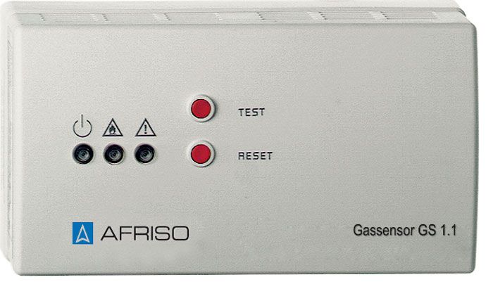
Betriebsanleitung

Gaswarngerät / Gassensor

                                                                      Typ: GS 1.1
                                                                      Typ: GS 2.1
                                                                      Typ: GS 4.1

                     Copyright 2021 AFRISO-EURO-INDEX GmbH. Alle Rechte vorbehalten.

                                                                      Lindenstraße 20
                                                                     74363 Güglingen
                                                              Telefon +49 7135 102-0
                                                            Service +49 7135 102-211
                                                            Telefax +49 7135 102-147
                                                                      info@afriso.com
Version: 09.2021.0
                                                                       www.afriso.com
ID: 900.000.0260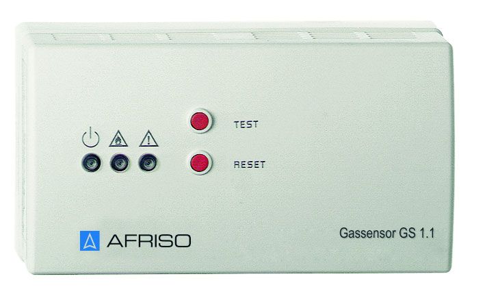
Über diese Betriebsanleitung                                    DE

1   Über diese Betriebsanleitung
    Diese Betriebsanleitung beschreibt die Gaswarngeräte „GS 1.1/GS 2.1“ und
    den Gassensor „GS 4.1“ (im Folgenden auch „Produkt“). Diese Betriebsan-
    leitung ist Teil des Produkts.
    •   Sie dürfen das Produkt erst benutzen, wenn Sie die Betriebsanleitung
        vollständig gelesen und verstanden haben.
    •   Stellen Sie sicher, dass die Betriebsanleitung für alle Arbeiten an und mit
        dem Produkt jederzeit verfügbar ist.
    •   Geben Sie die Betriebsanleitung und alle zum Produkt gehörenden
        Unterlagen an alle Benutzer des Produkts weiter.
    •   Wenn Sie der Meinung sind, dass die Betriebsanleitung Fehler, Wider-
        sprüche oder Unklarheiten enthält, wenden Sie sich vor Benutzung des
        Produkts an den Hersteller.
    Diese Betriebsanleitung ist urheberrechtlich geschützt und darf ausschließ-
    lich im rechtlich zulässigen Rahmen verwendet werden. Änderungen vorbe-
    halten.
    Für Schäden und Folgeschäden, die durch Nichtbeachtung dieser Betriebs-
    anleitung sowie Nichtbeachten der am Einsatzort des Produkts geltenden
    Vorschriften, Bestimmungen und Normen entstehen, übernimmt der Herstel-
    ler keinerlei Haftung oder Gewährleistung.

                                                  GS 1.1./GS 2.1/GS 4.1           2
Informationen zur Sicherheit                               DE

2     Informationen zur Sicherheit
2.1   Warnhinweise und Gefahrenklassen
      In dieser Betriebsanleitung finden Sie Warnhinweise, die auf potenzielle
      Gefahren und Risiken aufmerksam machen. Zusätzlich zu den Anweisungen
      in dieser Betriebsanleitung müssen Sie alle am Einsatzort des Produktes
      geltenden Bestimmungen, Normen und Sicherheitsvorschriften beachten.
      Stellen Sie vor Verwendung des Produktes sicher, dass Ihnen alle Bestim-
      mungen, Normen und Sicherheitsvorschriften bekannt sind und dass sie
      befolgt werden.
      Warnhinweise sind in dieser Betriebsanleitung mit Warnsymbolen und Sig-
      nalwörtern gekennzeichnet. Abhängig von der Schwere einer Gefährdungs-
      situation werden Warnhinweise in unterschiedliche Gefahrenklassen unter-
      teilt.

                                      GEFAHR
      GEFAHR macht auf eine unmittelbar gefährliche Situation aufmerksam, die
      bei Nichtbeachtung unweigerlich einen schweren oder tödlichen Unfall zur
      Folge hat.

                                  HINWEIS
      HINWEIS macht auf eine möglicherweise gefährliche Situation aufmerksam,
      die bei Nichtbeachtung Sachschäden zur Folge haben kann.

      Zusätzlich werden in dieser Betriebsanleitung folgende Symbole verwendet:
                     Dies ist das allgemeine Warnsymbol. Es weist auf die
                     Gefahr von Verletzungen und Sachschäden hin. Befolgen
                     Sie alle im Zusammenhang mit diesem Warnsymbol
                     beschriebenen Hinweise, um Unfälle mit Todesfolge, Verlet-
                     zungen und Sachschäden zu vermeiden.

                     Dieses Symbol warnt vor gefährlicher elektrischer Span-
                     nung. Wenn dieses Symbol in einem Warnhinweis gezeigt
                     wird, besteht die Gefahr eines elektrischen Schlags.

                                                GS 1.1./GS 2.1/GS 4.1          3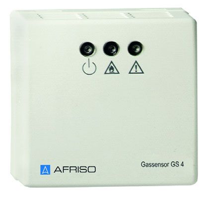
Informationen zur Sicherheit                              DE

2.2   Bestimmungsgemäße Verwendung
      Die Produkte eignen sich ausschließlich zur Überwachung der unteren
      Explosionsgrenze (UEG) von Gasen in der Raumluft. Die Produkte dürfen
      nur in privat genutzten Räumen verwendet werden. Die Produkte eignen sich
      für folgende Gase bis maximal 20 % UEG:

          Gase                       Art.-Nr.
          Methan (Erdgas)            Gaswarngerät GS 1.1, GS 2.1 (61184,
                                     61185) Gassensor GS 4.1 (61188)
          Propan/Butan               Gaswarngerät GS 1.1, GS 2.1 (61186,
                                     61187) Gassensor GS 4.1 (61189)

      Eine andere Verwendung ist nicht bestimmungsgemäß und verursacht
      Gefahren.
      Stellen Sie vor Verwendung des Produkts sicher, dass das Produkt für die
      von Ihnen vorgesehene Verwendung geeignet ist. Berücksichtigen Sie dabei
      mindestens folgendes:
      •     Alle am Einsatzort geltenden Bestimmungen, Normen und Sicherheits-
            vorschriften
      •     Alle für das Produkt spezifizierten Bedingungen und Daten
      •     Die Bedingungen der von Ihnen vorgesehenen Anwendung
      Führen Sie darüber hinaus eine Risikobeurteilung in Bezug auf die konkrete,
      von Ihnen vorgesehene Anwendung nach einem anerkannten Verfahren
      durch und treffen Sie entsprechende dem Ergebnis alle erforderlichen
      Sicherheitsmaßnahmen. Berücksichtigen Sie dabei auch die möglichen Fol-
      gen eines Einbaus oder einer Integration des Produkts in ein System oder in
      eine Anlage.
      Führen Sie bei der Verwendung des Produkts alle Arbeiten ausschließlich
      unter den in der Betriebsanleitung und auf dem Typenschild spezifizierten
      Bedingungen und innerhalb der spezifizierten technischen Daten und in
      Übereinstimmung mit allen am Einsatzort geltenden Bestimmungen, Nor-
      men und Sicherheitsvorschriften durch.

                                                   GS 1.1./GS 2.1/GS 4.1          4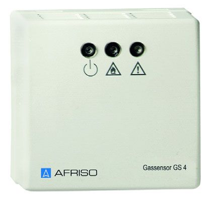
Informationen zur Sicherheit                                  DE

2.3   Vorhersehbare Fehlanwendung
      Das Produkt darf insbesondere in folgenden Fällen und für folgende Zwecke
      nicht angewendet werden:
      •   In gewerblich genutzten Bereichen
      •   In Räumen, in denen sich dauerhaft Chemikalien in der Umgebungsluft
          befinden
      •   Explosionsgefährdete Umgebung
          - Bei Betrieb in explosionsgefährdeten Bereichen kann Funkenbildung zu
            Verpuffungen, Brand oder Explosionen führen.
      •   Einsatz des Produkts als Ausrüstungsteil mit Sicherheitsfunktion oder zur
          Implementierung einer Sicherheitsfunktion oder einer sicherheitsgerich-
          teten Funktion

2.4   Qualifikation des Personals
      Montage, Inbetriebnahme, Wartung und Außerbetriebnahme dieses Pro-
      dukts dürfen nur von Fachkräften vorgenommen werden, die über alle am
      Einsatzort der Produkts erforderlichen Qualifikation im Zusammenhang mit
      Gaswarneinrichtungen und deren Funktionsprüfung verfügen und folgende
      Anforderungen erfüllen:
      •   Qualifikation zur befähigten Person zur Prüfung von Gaswarneinrichtun-
          gen
      Arbeiten an und mit diesem Produkt dürfen nur von Fachkräften vorgenom-
      men werden, die den Inhalt dieser Betriebsanleitung und alle zum Produkt
      gehörenden Unterlagen kennen und verstehen.
      Die Fachkräfte müssen aufgrund ihrer fachlichen Ausbildung, Kenntnisse
      und Erfahrungen in der Lage sein, mögliche Gefährdungen vorherzusehen
      und zu erkennen, die durch den Einsatz des Produkts entstehen können.
      Den Fachkräften müssen alle geltenden Bestimmungen, Normen und
      Sicherheitsvorschriften, die bei Arbeiten an und mit dem Produkt beachtet
      werden müssen, bekannt sein.

2.5   Persönliche Schutzausrüstung
      Verwenden Sie immer die erforderliche persönliche Schutzausrüstung.
      Berücksichtigen Sie bei Arbeiten an und mit dem Produkt auch, dass am Ein-
      satzort Gefährdungen auftreten können, die nicht direkt vom Produkt ausge-
      hen.

                                                   GS 1.1./GS 2.1/GS 4.1          5
Transport und Lagerung                                    DE

2.6   Veränderungen am Produkt
      Führen Sie ausschließlich solche Arbeiten an und mit dem Produkt durch, die
      in dieser Betriebsanleitung beschrieben sind. Nehmen Sie keine Verände-
      rungen vor, die in dieser Betriebsanleitung nicht beschrieben sind.

3     Transport und Lagerung
      Das Produkt kann durch unsachgemäßen Transport und Lagerung beschä-
      digt werden.

                                   HINWEIS
    UNSACHGEMÄSSE HANDHABUNG
    • Stellen Sie sicher, dass während des Transports und der Lagerung des Pro-
      dukts die spezifizierten Umgebungsbedingungen eingehalten werden.
    • Benutzen Sie für den Transport die Originalverpackung.
    • Lagern Sie das Produkt nur in trockener, sauberer Umgebung.
    • Stellen Sie sicher, dass das Produkt bei Transport und Lagerung stoßge-
      schützt ist.
    Nichtbeachtung dieser Anweisungen kann zu Sachschäden führen.

                                                 GS 1.1./GS 2.1/GS 4.1          6
Produktbeschreibung                                    DE

4   Produktbeschreibung
    Gaswarngerät GS 1.1
    Das Gaswarngerät GS 1.1 ist ein Warngerät für die Wandmontage. Es bein-
    haltet einen Gassensor und die Auswerteelektronik.
    Das Gaswarngerät GS 1.1 besteht aus einem zweiteiligen Gehäuse, einer
    Grundplatine mit Versorgungsteil, einer Hupe, einem integriertem Sensor
    und den Anschlussklemmen. Das Gaswarngerät GS 1.1 hat einen internen
    Alarmspeicher.
    Gaswarngerät GS 2.1
    An das Gaswarngerät GS 2.1 kann zusätzlich der externe Gassensor GS 4.1
    als zweite Messstelle angeschlossen werden. Das Gaswarngerät GS 2.1
    verfügt über ein Ausgangsrelais.
    Das Gaswarngerät GS 2.1 erkennt Drahtbruch und Kurzschluss zum exter-
    nen Gassensor. Für beide Messstellen steht ein gemeinsames Alarmrelais
    zur Verfügung. Mit dem Gaswarngerät GS 2.1 und dem Gassensor GS 4.1
    können zwei Messstellen in unterschiedlichen Räumen auf Gas überwacht
    werden. An beiden Messstellen wird optisch der Betriebszustand angezeigt.
    Der akustische Alarm wird nur am Gaswarngerät GS 2.1 ausgelöst.
    Gassensor GS 4.1
    Der externe Gassensor GS 4.1 ist als zweite Messstelle für das Gaswarnge-
    rät GS 2.1 vorgesehen.

                                              GS 1.1./GS 2.1/GS 4.1         7
Produktbeschreibung DE
4.1 Übersicht
E A. Grüne LED: Normalbe-
trieb
D B. Rote LED: Alarm
C. Gelbe LED: Fehler
D. RESET: Quittiertaste für
Hupe und Alarm
E. TEST: Testtaste
A B C
Abbildung 1: Gaswarngerät GS 1.1 und GS 2.1
A B C A. Grüne LED: Normalbe-
trieb
B. Rote LED: Alarm
C. Gelbe LED: Fehler
Abbildung 2: Gassensor GS 4.1
GS 1.1./GS 2.1/GS 4.1 8Produktbeschreibung DE
4.2 Anwendungsbeispiele
30-40 cm
max. 5 m
Abbildung 3: Anwendungsbeispiel Gasüberwachung für Propan
30-40 cm
max. 5 m
Abbildung 4: Anwendungsbeispiel Gasüberwachung für Methan
GS 1.1./GS 2.1/GS 4.1 9Produktbeschreibung DE
4.3 Funktion
Das Gaswarngerät GS 1.1 löst optischen und akustischen Alarm aus, wenn
die untere Explosionsgrenze (Schwellenwert 20 % UEG) erreicht oder über-
schritten wird (Alarmzustand).
• Die rote Alarm-LED leuchtet.
• Der akustische Alarm ertönt.
Mit der Reset-Taste kann der akustische Alarm deaktiviert werden. Die rote
LED leuchtet so lange, bis die Gaskonzentration unter den Schwellenwert
sinkt und der Alarmzustand beendet ist.
Beim Gaswarngerät GS 2.1 wird beim Auslösen des optischen und akusti-
schen Alarms zusätzlich das integrierte Ausgangsrelais geschaltet. Der
akustische Alarm wird nur am Gaswarngerät GS 2.1 selbst ausgelöst, nicht
an einem eventuell angeschlossenen Gassensor GS 4.1.
Die rote LED leuchtet sowohl am Gaswarngerät 2.1 als auch am Gassensor
GS 4.1 so lange , bis die Gaskonzentration an beiden Messstellen unter den
Schwellenwert gesunken ist und die Reset-Taste gedrückt wurde.
Bei den Sensoren zur Gasdetektion handelt es sich um Halbleitersensoren.
Die zu erwartende Lebensdauer eines Halbleitersensors beträgt ungefähr
5 Jahre.
4.4 Zulassungsdokumente, Bescheinigungen, Erklärungen
Das Produkt entspricht:
• EMV-Richtlinie (2014/30/EU)
• Niederspannungsrichtlinie (2014/35/EU)
GS 1.1./GS 2.1/GS 4.1 10Produktbeschreibung DE
4.5 Technische Daten
Gaswarngeräte GS 1.1 und GS 2.1
Parameter Wert
Einsatzbedingungen
Überwachung Methan oder Propan/Butan
Einsatzbereich Raumluft, kein Einsatz in gewerb-
lich genutzten Räumen
Entfernung Gasquelle Produkt Maximal 5 m
Montagehöhe Propan/Butan Maximal 0,4 m über dem Boden
Montagehöhe Methan Maximal 0,4 m unter Deckenhöhe
Allgemeine Daten
Abmessungen Gehäuse (B x H x T) 156 x 88 x 45 mm
Gewicht Ca. 0,9 g
Anschlüsse Schraubklemmen
Emissionen Min. 50 dB(A), A-bewerteter Schall-
druckpegel akustischer Alarm bei
einem Meter Abstand
Alarmwert Ca. 20 % UEG
Lebensdauer Ca. 5 Jahre
Umgebungsbedingungen
Umgebungstemperatur 0 ... 40 °C
Lagerungstemperatur -10 ... 60 °C
Relative Luftfeuchtigkeit 5 ... 90 %
Elektrische Daten
Versorgungsspannung AC 230 V
Nennleistung 5 VA
Nur GS 2.1: Potentialfreier Wechsler AC 230 V, 2 A
Schutzart IP 20
Schutzklasse (EN 61010-1) II
GS 1.1./GS 2.1/GS 4.1 11Produktbeschreibung DE
Gassensor GS 4.1
Parameter Wert
Allgemeine Daten
Abmessungen Gehäuse (B x H x T) 80 x 80 x 36 mm
Gewicht Ca. 0,5 g
Werkstoff Gehäuse Kunststoff
Anschluss Schraubklemmen
Leiterwiderstand Max. 100 Ohm Hin- und Rückleiter
Luftdruck 900 hPa bis 1100 hPa
Alarmwert Ca. 20 % UEG
Lebensdauer Ca. 5 Jahre
Umgebungsbedingungen
Umgebungstemperatur 0 ... 40 °C
Lagerungstemperatur -10 ... 60 °C
Relative Luftfeuchtigkeit 5 ... 90 %
Elektrische Daten
Spannungsversorgung Über GS 2.1 (12 V DC, < 100 mA)
Schutzart IP 20
Schutzklasse (EN 61010-1) II
GS 1.1./GS 2.1/GS 4.1 12Montage DE
5 Montage
5.1 Montage vorbereiten
WARNUNG
UNZUREICHENDE GASDETEKTION
Eine falsche Montageposition und/oder Nichteinhaltung der Umgebungsbedin-
gungen führen dazu, dass das Gaswarngerät austretendes Gas nicht ordnungs-
gemäß detektieren kann. Dies kann Explosionen oder Vergiftungen zur Folge
haben.
• Stellen Sie sicher, dass das Produkt so montiert wird, dass austretendes
Gas von einem im Raum vorherrschenden Luftstrom in Richtung des Pro-
dukts transportiert wird.
• Stellen Sie sicher, dass am Montageort alle in dieser Betriebsanleitung spe-
zifizierten Umgebungsbedingungen und Abstände eingehalten werden.
Nichtbeachtung dieser Anweisungen kann zu Tod, schweren Verletzun-
gen oder Sachschäden führen.
HINWEIS
CHEMIKALIEN IN DER UMGEBUNGSLUFT
Chemikalien in der Umgebungsluft verkürzen die Lebensdauer des Produkts
und können zu falschen Messungen der Gaskonzentration führen.
• Stellen Sie sicher, dass das Produkt nicht in Räumen montiert wird, in denen
sich dauerhaft Chemikalien in der Umgebungsluft befinden.
• Stellen Sie sicher, dass nach Verarbeitung von Sanitärsilikon, Acryl und ähn-
lichen Stoffen im Detektionsbereich des Produkts eine Trocknungszeit von
einer Woche eingehalten wird, bevor das Produkt montiert wird.
Nichtbeachtung dieser Anweisung kann zu Sachschäden führen.
Stellen Sie sicher, dass das Produkt jederzeit zugänglich und einsehbar
ist.
Stellen Sie sicher, dass das Produkt zwischen einer möglichen Zünd-
quelle und der zu überwachenden Gasquelle so nahe wie möglich an der
zu überwachenden Gasquelle montiert wird.
GS 1.1./GS 2.1/GS 4.1 13Montage DE
5.1.1 Platzierung des Produkts
Die Produkte dürfen in folgenden Bereichen nicht montiert werden:
• Bereiche, in denen das Produkt einen Gasaustritt nicht detektieren
kann (beispielsweise hinter Vorhängen oder in Schränken).
• In unmittelbarer Nähe eines Herdes oder über einem Waschbecken
• Neben Türen, Fenstern, Belüftung, Ventilator, Klimaanlage
• In Bereichen, in denen Staub oder Schmutz das Produkt verschmutzen
können.
5.1.2 Detektion von Propan/Butan
Propan und Butan sind schwerer als Luft. Daher muss das Produkt zur
Detektion von Propan und Butan im Bodenbereich des zu überwachen-
den Raums montiert sein.
Stellen Sie sicher, dass im Boden oder in Bodennähe keine Öffnungen
vorhanden sind, durch die das Gas in tieferliegende Räume entweichen
kann.
Stellen Sie sicher, dass das Produkt nicht direkt neben einem Ausgang
angebracht wird.
- Propan und Butan können sich über den Boden ausbreiten.
1. Montieren Sie das Produkt in Bodennähe in einer Höhe von 30 - 40 cm
über dem Boden und in einem Abstand von maximal 5 m von der zu
überwachenden Gasquelle.
- Bei abfallenden Böden muss das Produkt am tiefsten Punkt des abfal-
lenden Bodens montiert sein.
5.1.3 Detektion von Methan
Methan ist leichter als Luft. Daher muss das Produkt zur Detektion von
Methan unterhalb der Decke des zu überwachenden Raums montiert
sein. Stellen Sie sicher, dass in der Nähe des Produkts keine Wandöff-
nungen (Tür, Durchreiche, Dunstabzug) vorhanden sind, durch die das
Gas in angrenzende Räume entweichen kann.
1. Montieren Sie das Produkt 30 - 40 cm unterhalb der Raumdecke und
in einem Abstand von maximal 5 m von der zu überwachenden Gas-
quelle.
- Das Produkt muss oberhalb der höchsten Tür- oder Fensteröffnung
des Raumes montiert sein.
- Bei schrägen Decken muss das Produkt am höchsten Punkt der
Decke montiert sein.
GS 1.1./GS 2.1/GS 4.1 14Montage DE
5.1.4 Querempfindlichkeit
Sensoren zur Gasdetektion können neben den zu detektierenden Gasen
auch auf andere gasförmige Stoffe in der Umgebungsluft reagieren (bei-
spielsweise Reinigungsmittel oder Lösemittel).
Stellen Sie sicher, dass keine Stoffe im Detektionsbereich des Produkts
verwendet werden, die Lösungsmittel oder andere Chemikalien ausga-
sen.
- Diese Stoffe können einen Alarm auslösen.
5.2 Produkt montieren
Stellen Sie sicher, dass die technischen Daten und alle Vorgaben zur
Montage eingehalten werden.
1. Befestigen Sie das Gehäuse mittels Schrauben an der Wand.
- Auf der Gehäuserückseite befinden sich Löcher zur Befestigung.
5.3 Elektrischer Anschluss
GEFAHR
ELEKTRISCHER SCHLAG
• Stellen Sie sicher, dass durch die Art der elektrischen Installation der Schutz
gegen elektrischen Schlag (Schutzklasse, Schutzisolierung) nicht vermin-
dert wird.
Nichtbeachtung dieser Anweisungen führt zu Tod oder schweren Verlet-
zungen.
GEFAHR
ELEKTRISCHER SCHLAG DURCH SPANNUNGSFÜHRENDE TEILE
• Unterbrechen Sie vor Beginn der Arbeiten die Netzspannung und sichern
Sie diese gegen Wiedereinschalten.
• Stellen Sie sicher, dass durch elektrisch leitfähige Gegenstände oder
Medien keine Gefährdungen ausgehen können.
Nichtbeachtung dieser Anweisungen führt zu Tod oder schweren Verlet-
zungen.
GS 1.1./GS 2.1/GS 4.1 15Montage DE
Abbildung 5: Elektrischer Anschluss GS 1.1
A
B
C
A. Gaswarngerät GS 2.1 C. Gassensor GS 4.1
B. Jumper (Sensor S1)
Abbildung 6: Elektrischer Anschluss; Relais abgefallen entspricht Alarmfall
GS 1.1./GS 2.1/GS 4.1 16Montage DE
Im Gaswarngerät GS 2.1 kann mit dem Jumper (B) der Sensor S1 zur Gas-
detektion im Gaswarngerät GS 2.1 aktiviert oder deaktiviert werden. Die
Funktion ist abhängig davon, ob ein Gassensor GS 4.1 angeschlossen ist
oder nicht. Die folgende Tabelle zeigt, bei welchen Jumperstellungen der
Sensor S1 zur Gasdetektion im Gaswarngerät GS 2.1 aktiv oder inaktiv ist:
Gassensor GS 4.1 Sensor S1 Jumperstellung
GS 4.1 angeschlossen S1 aktiv
GS 4.1 nicht angeschlossen S1 nicht aktiv
Das Produkt ist betriebsbereit, sobald es elektrisch angeschlossen ist.
GS 1.1./GS 2.1/GS 4.1 17Inbetriebnahme DE
6 Inbetriebnahme
Stellen Sie sicher, dass vor der Inbetriebnahme eine Funktionsprüfung
von Fachkräften (siehe "Qualifikation des Personals") durchgeführt wird.
6.1 Funktionsprüfung durchführen
VORSICHT
UNSACHGEMÄSSE HANDHABUNG VON PRÜFGAS
• Beachten Sie die Sicherheitsdatenblätter des Prüfgasherstellers.
Nichtbeachtung dieser Anweisungen kann zu Verletzungen führen.
Die Funktionsprüfung darf nur von Fachkräften durchgeführt werden, die auf
Grund ihrer fachlichen Ausbildung und Erfahrung ausreichende Kenntnisse
auf dem Gebiet der Funktionsprüfung von Gaswarneinrichtungen haben und
mit den hierfür geltenden Regeln, Vorschriften und Bestimmungen vertraut
sind.
Wenn ein Gassensor GS 4.1 angeschlossen ist, muss die Funktionsprüfung
für das Gaswarngerät GS 2.1 und für den Gassensor GS 4.1 separat durch-
geführt werden.
Für die Funktionsprüfung des Produkts muss ein Prüfgas verwendet werden,
das alle Einsatzort des Produktes geltenden Bestimmungen, Normen und
Sicherheitsvorschriften erfüllt.
1. Lassen Sie das Prüfgas in unmittelbarer Nähe der Lüftungsschlitze in das
zu prüfende Produkt einströmen.
- Wenn der Test erfolgreich ist, ertönt ein akustischer Alarm (Hupe) und
die rote LED leuchtet.
2. Unterbrechen Sie die Prüfgaszufuhr, sobald der Alarm ausgelöst wird.
3. Drücken Sie zweimal die Reset-Taste.
- Der akustische Alarm verstummt nach dem ersten Drücken. Die rote
LED erlischt nach dem zweiten Drücken.
- Wenn die rote LED nicht erlischt, ist das Prüfgas noch nicht vollständig
aus dem Produkt entwichen.
4. Dokumentieren Sie die Ergebnisse der Funktionsprüfung.
Wenn sich der Alarm nicht quittieren lässt, senden Sie das Produkt zur Nach-
kalibrierung an den Hersteller.
GS 1.1./GS 2.1/GS 4.1 18Betrieb DE
7 Betrieb
7.1 Bedien- und Anzeigeelemente
Am Produkt GS 1.1 GS 2.1 GS 4.1
Rote LED Alarm
Grüne LED Betrieb
Gelbe LED Störung
Hupe Alarm Alarm -
Relais - Alarm -
Reset-Taste Einmal drücken: Hupe aus -
Zweimal drücken: Alarm aus
Testtaste Test der Hupe und der roten LED. -
Mit der Testtaste kann keine Funkti-
onsprüfung durchgeführt werden
(siehe "Funktionsprüfung durchfüh-
ren").
7.2 Alarm
Wenn das Produkt eine erhöhte Gaskonzentration erfasst, leuchtet die rote
LED und ein akustischer Alarm ertönt.
Verhalten im Alarmfall
1. Löschen Sie alle offenen Flammen, Kerzen und Rauchwaren.
2. Unterbrechen Sie die Gaszufuhr.
3. Schalten Sie keine elektrischen Geräte, Taschenlampen oder ähnliches
ein oder aus.
4. Öffnen Sie Fenster und Türen und lüften Sie den Raum gründlich.
5. Benutzen Sie kein Telefon in dem Gebäude, in dem der Gasaustritt ver-
mutet wird.
GS 1.1./GS 2.1/GS 4.1 19Wartung DE
8 Wartung
VORSICHT
UNSACHGEMÄSSE HANDHABUNG VON PRÜFGAS
• Beachten Sie die Sicherheitsdatenblätter des Prüfgasherstellers.
Nichtbeachtung dieser Anweisungen kann zu Verletzungen führen.
Wartung und Funktionsprüfung dürfen nur von Fachkräften durchgeführt
werden (siehe "Funktionsprüfung durchführen").
8.1 Wartungsintervalle
Stellen Sie sicher, dass die Produkte und deren Umgebung sauber,
zugänglich und einsehbar sind.
Zeitpunkt Tätigkeit
Vor Inbetriebnahme Lassen Sie eine Funktionsprüfung von Fachkräf-
ten durchführen, siehe Kapitel "Funktionsprüfung
Mindestens einmal jähr-
durchführen".
lich
Senden Sie das Produkt zur Wartung mit Kalibriergas an den Hersteller.
GS 1.1./GS 2.1/GS 4.1 20Störungsbeseitigung DE
9 Störungsbeseitigung
Störungen, die nicht durch die im Kapitel beschriebenen Maßnahmen besei-
tigt werden können, dürfen nur durch den Hersteller behoben werden.
Problem Mögliche Ursache Fehlerbehebung
Gelbe LED leuchtet Drahtbruch oder Kurz- Prüfen Sie die elektri-
schluss sche Verbindung zwi-
schen dem Gaswarnge-
rät GS 2.1 und dem
Gassensor GS 4.1
Alarm lässt sich nicht Kalibrierung fehlerhaft Senden Sie das Produkt
quittieren zur Nachkalibrierung an
den Hersteller
Sonstige Störungen - Bitte wenden Sie sich
an die AFRISO-Service
Hotline
10 Außerbetriebnahme und Entsorgung
Entsorgen Sie das Produkt nach den geltenden Bestimmungen, Normen und
Sicherheitsvorschriften.
Elektronikteile dürfen nicht mit dem Hausmüll entsorgt werden.
1. Trennen Sie das Produkt von der Versorgungsspannung.
2. Demontieren Sie das Produkt (siehe Kapitel "Montage"
in umgekehrter Reihenfolge).
3. Entsorgen Sie das Produkt.
11 Rücksendung
Vor einer Rücksendung Ihres Produkts müssen Sie sich mit uns in Verbin-
dung setzen (service@afriso.de).
12 Gewährleistung
Informationen zur Gewährleistung finden Sie in unseren Allgemeinen
Geschäftsbedingungen im Internet unter www.afriso.com oder in Ihrem Kauf-
vertrag.
GS 1.1./GS 2.1/GS 4.1 21Ersatzteile und Zubehör DE
13 Ersatzteile und Zubehör
HINWEIS
UNGEEIGNETE TEILE
• Verwenden Sie nur Original Ersatz- und Zubehörteile des Herstellers.
Nichtbeachtung dieser Anweisung kann zu Sachschäden führen.
Produkt
Artikelbezeichnung Art.-Nr. Abbildung
Gaswarngerät GS 1.1 Methan 61184
Gaswarngerät GS 1.1 Propan/Butan 61186
Gaswarngerät GS 2.1 Methan 61185
Gaswarngerät GS 2.1 Propan/Butan 61187
Gassensor GS 4.1 Methan 61188
Gassensor GS 4.1 Propan/Butan 61189
Ersatzteile und Zubehör
Artikelbezeichnung Art.-Nr. Abbildung
Ereignismeldesystem EMS 220 90220 -
Ereignismeldesystem EMS 442 90442 -
GS 1.1./GS 2.1/GS 4.1 22Anhang DE
14 Anhang
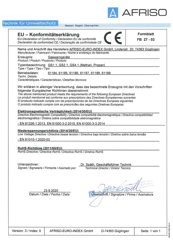
14.1 EU-Konformitätserklärung
GS 1.1./GS 2.1/GS 4.1 23Operating
instructions
Gas alarm unit / gas sensor
Type: GS 1.1
Type: GS 2.1
Type: GS 4.1
Copyright 2021 AFRISO-EURO-INDEX GmbH. All rights reserved.
Lindenstraße 20
74363 Güglingen
Telephone +49 7135 102-0
Service +49 7135 102-211
Telefax +49 7135 102-147
info@afriso.com
Version: 09.2021.0
www.afriso.com
ID: 900.000.0260About these operating instructions EN
1 About these operating instructions
These operating instructions describe the gas alarm units "GS 1.1/GS 2.1"
and the gas sensor "GS 4.1" (also referred to as "product" in these operating
instructions). These operating instructions are part of the product.
• You may only use the product if you have fully read and understood these
operating instructions.
• Verify that these operating instructions are always accessible for any type
of work performed on or with the product.
• Pass these operating instructions as well as all other product-related doc-
uments on to all owners of the product.
• If you feel that these operating instructions contain errors, inconsisten-
cies, ambiguities or other issues, contact the manufacturer prior to using
the product.
These operating instructions are protected by copyright and may only be
used as provided for by the corresponding copyright legislation. We reserve
the right to modifications.
The manufacturer shall not be liable in any form whatsoever for direct or con-
sequential damage resulting from failure to observe these operating instruc-
tions or from failure to comply with directives, regulations and standards and
any other statutory requirements applicable at the installation site of the prod-
uct.
GS 1.1./GS 2.1/GS 4.1 2Information on safety EN
2 Information on safety
2.1 Safety messages and hazard categories
These operating instructions contain safety messages to alert you to poten-
tial hazards and risks. In addition to the instructions provided in these oper-
ating instructions, you must comply with all directives, standards and safety
regulations applicable at the installation site of the product. Verify that you are
familiar with all directives, standards and safety regulations and ensure com-
pliance with them prior to using the product.
Safety messages in these operating instructions are highlighted with warning
symbols and warning words. Depending on the severity of a hazard, the
safety messages are classified according to different hazard categories.
DANGER
DANGER indicates a hazardous situation, which, if not avoided, will result in
death or serious injury.
NOTICE
NOTICE indicates a hazardous situation, which, if not avoided, can result in
equipment damage.
In addition, the following symbols are used in these operating instructions:
This is the general safety alert symbol. It alerts to injury haz-
ards or equipment damage. Comply with all safety instruc-
tions in conjunction with this symbol to help avoid possible
death, injury or equipment damage.
This symbol alerts to hazardous electrical voltage. If this
symbol is used in a safety message, there is a hazard of
electric shock.
GS 1.1./GS 2.1/GS 4.1 3Information on safety EN
2.2 Intended use
The products may only be used to monitor the lower explosive limit (LEL) of
gases in ambient air. The products may only be used in privately used rooms.
The products may only be used for the following gases up to 20 % LEL:
Gases Part no.
Methane (natural gas) Gas alarm unit GS 1.1, GS 2.1 (61184,
61185) gas sensor GS 4.1 (61188)
Propane/butane Gas alarm unit GS 1.1, GS 2.1 (61186,
61187) gas sensor GS 4.1 (61189)
Any use other than the application explicitly permitted in these operating
instructions is not permitted and causes hazards.
Verify that the product is suitable for the application planned by you prior to
using the product. In doing so, take into account at least the following:
• All directives, standards and safety regulations applicable at the installa-
tion site of the product
• All conditions and data specified for the product
• The conditions of the planned application
In addition, perform a risk assessment in view of the planned application,
according to an approved risk assessment method, and implement the
appropriate safety measures, based on the results of the risk assessment.
Take into account the consequences of installing or integrating the product
into a system or a plant.
When using the product, perform all work and all other activities in conjunc-
tion with the product in compliance with the conditions specified in the oper-
ating instructions and on the nameplate, as well as with all directives, stand-
ards and safety regulations applicable at the installation site of the product.
GS 1.1./GS 2.1/GS 4.1 4Information on safety EN
2.3 Predictable incorrect application
The product must never be used in the following cases and for the following
purposes:
• In commercially used rooms
• In rooms where there are permanently chemicals in the ambient air
• Hazardous area (EX)
- If the product is operated in hazardous areas, sparks may cause defla-
grations, fires or explosions.
• Use of the product as equipment with a safety function or use of the prod-
uct for the implementation of a safety function or a safety-related function
2.4 Qualification of personnel
This product may only be mounted, commissioned, maintained and decom-
missioned by qualified persons with all qualifications required at the installa-
tion site of the product in conjunction with gas alarm equipment and the func-
tion tests of such gas alarm equipment, and who meet the following
requirements:
• Certification as qualified person for testing gas alarm equipment accord-
ing to all directives, standards and regulations applicable at the installa-
tion site of the product
Only appropriately trained persons who are familiar with and understand the
contents of these operating instructions and all other pertinent product doc-
umentation are authorized to work on and with this product.
These persons must have sufficient technical training, knowledge and expe-
rience and be able to foresee and detect potential hazards that may be
caused by using the product.
All persons working on and with the product must be fully familiar with all
directives, standards and safety regulations that must be observed for per-
forming such work.
2.5 Personal protective equipment
Always wear the required personal protective equipment. When performing
work on and with the product, take into account that hazards may be present
at the installation site which do not directly result from the product itself.
GS 1.1./GS 2.1/GS 4.1 5Transport and storage EN
2.6 Modifications to the product
Only perform work on and with the product which is explicitly described in
these operating instructions. Do not make any modifications to the product
which are not described in these operating instructions.
3 Transport and storage
The product may be damaged as a result of improper transport or storage.
NOTICE
INCORRECT HANDLING
• Verify compliance with the specified ambient conditions during transport or
storage of the product.
• Use the original packaging when transporting the product.
• Store the product in a clean and dry environment.
• Verify that the product is protected against shocks and impact during trans-
port and storage.
Failure to follow these instructions can result in equipment damage.
GS 1.1./GS 2.1/GS 4.1 6Product description EN
4 Product description
Gas alarm unit GS 1.1
The gas alarm GS 1.1 unit is an alarm unit for wall mounting. It comprises a
gas sensor and the evaluation electronics.
The gas alarm unit GS 1.1 consists of a housing (two parts), a PCB with sup-
ply unit, a horn, an integrated sensor and the connection terminals. The gas
alarm unit GS 1.1 is equipped with an internal alarm memory.
Gas alarm unit GS 2.1
The external gas sensor GS 4.1 can be connected to the gas alarm unit
GS 2.1 as a second measuring point. The gas alarm unit GS 2.1 is equipped
with an output relay.
The gas alarm unit GS 2.1 detects line interruptions and short circuits in the
connection to the external gas sensor. A common alarm relay is available for
both measuring points. With the gas alarm unit GS 2.1 and the gas sensor
GS 4.1, it is possible to monitor two measuring points in different rooms for
gas. The operating state is visually indicated at both measuring points. An
audible alarm is only triggered at the gas alarm unit GS 2.1.
Gas sensor GS 4.1
The external gas sensor GS 4.1 is used as a second measuring point for the
gas alarm unit GS 2.1.
GS 1.1./GS 2.1/GS 4.1 7Product description EN
4.1 Overview
E A. Green LED: Normal oper-
ation
D B. Red LED: Alarm
C. Yellow LED: Error
D. RESET: Acknowledge key
for horn and alarm
E. TEST: Test key
A B C
Fig. 1: Gas alarm units GS 1.1 and GS 2.1
A B C A. Green LED: Normal oper-
ation
B. Red LED: Alarm
C. Yellow LED: Error
Fig. 2: Gas sensor GS 4.1
GS 1.1./GS 2.1/GS 4.1 8Product description EN
4.2 Application examples
30 - 40 cm
max. 5 m
Fig. 3: Application example gas monitoring for propane
30 - 40 cm
max. 5 m
Fig. 4: Application example gas monitoring for methane
GS 1.1./GS 2.1/GS 4.1 9Product description EN
4.3 Function
The gas alarm unit GS 1.1 triggers visual and audible alarms when the lower
explosive limit (threshold value 20 % LEL) is reached or exceeded (alarm
condition).
• The red alarm LED is on.
• The audible alarm sounds.
The audible alarm can be deactivated with the Reset button. The red LED
continues to be on until the gas concentration drops below the threshold
value and the alarm condition is terminated.
In the case of the gas alarm unit GS 2.1, the integrated output relay is
switched when the visual and audible alarms are triggered. The audible
alarm is only triggered at the gas alarm unit GS 2.1 itself, not at a connected
gas sensor GS 4.1.
The red LEDs at the gas alarm unit GS 2.1 and at the gas sensor GS 4.1
remain lit until the gas concentrations at both measuring points drop below
the threshold and the Reset button is pressed.
The sensors for gas detection are semiconductor sensors. The service life of
a semiconductor sensor is approximately 5 years.
4.4 Approvals, conformities, certifications
The product complies with:
• EMC Directive (2014/30/EU)
• Low Voltage Directive (2014/35/EU)
GS 1.1./GS 2.1/GS 4.1 10Product description EN
4.5 Technical data
Gas alarm units GS 1.1 and GS 2.1
Parameter Value
Application conditions
Monitoring Methane or propane/butane
Application area Ambient air, no application in com-
mercially used rooms
Distance between gas source and Maximum 5 m
product
Mounting height propane/butane Maximum 0.4 m above the floor
Mounting height methane Maximum 0.4 m below the ceiling
General specifications
Dimensions housing (W x H x D) 156 x 88 x 45 mm
Weight Approx. 0.9 g
Connections Screw terminals
Emissions Minimum 50 dB(A), A-weighted
sound pressure audible alarm at a
distance of one metre
Alarm value Approx. 20 % LEL
Service life Approx. 5 years
Ambient conditions
Ambient temperature 0 ... 40 °C
Storage temperature -10 ... 60 °C
Relative humidity 5 ... 90 %
Electrical data
Supply voltage AC 230 V
Nominal power 5 VA
GS 2.1 only: voltage-free changeover AC 230 V, 2 A
contact
Degree of protection IP 20
Protection class (EN 61010-1) II
GS 1.1./GS 2.1/GS 4.1 11Product description EN
Gas sensor GS 4.1
Parameter Value
General specifications
Dimensions housing (W x H x D) 80 x 80 x 36 mm
Weight Approx. 0.5 g
Housing material Plastic
Connection Screw terminals
Line resistance Maximum 100 Ohm supply and
return conductor
Atmospheric pressure 900 hPa to 1100 hPa
Alarm value Approx. 20 % LEL
Service life Approx. 5 years
Ambient conditions
Ambient temperature 0 ... 40 °C
Storage temperature -10 ... 60 °C
Relative humidity 5 ... 90 %
Electrical data
Supply voltage Via GS 2.1 (12 V DC, < 100 mA)
Degree of protection IP 20
Protection class (EN 61010-1) II
GS 1.1./GS 2.1/GS 4.1 12Mounting EN
5 Mounting
5.1 Preparing mounting
WARNING
INSUFFICIENT GAS DETECTION
If the gas alarm unit is installed at an incorrect position and/or if the specified
ambient conditions are not respected, the gas alarm unit cannot properly detect
escaping gas. This may result in explosions or poisoning.
• Verify that the product is installed in such a way that the airflow in the room
transports the gas towards the product.
• Verify compliance with all ambient conditions and distances at the installation
site as specified in the present operating instructions.
Failure to follow these instructions can result in death, serious injury or
equipment damage.
NOTICE
CHEMICALS IN THE AMBIENT AIR
Chemicals in the ambient air reduce the service life of the product and can incur
incorrect measurements of the gas concentration.
• Verify that the product is not installed in rooms whose ambient air contains
chemicals on a permanent basis.
• Verify that you allow a drying time of one week before mounting the product
if you have worked with sanitary silicone, acrylic and similar substances in
the detection area of the product.
Failure to follow these instructions can result in equipment damage.
Verify that the product is accessible and easy to oversee at all times.
Verify that the product is installed between a potential ignition source and
the gas source to be monitored as closely as possible to the gas source
to be monitored.
GS 1.1./GS 2.1/GS 4.1 13Mounting EN
5.1.1 Placing the product
The products must not be mounted in the following areas:
• Areas in which the product cannot detect escaping gas (for example,
behind curtains or in cupboards).
• In the immediate vicinity of a stove or above a sink
• Next to doors, windows, fans, air conditioning systems
• In areas in which dust or dirt can contaminate the product.
5.1.2 Detection of propane/butane
Propane and butane are heavier than air. Therefore, the product must be
mounted in the floor area of the monitored room if propane or butane are
to be detected.
Verify that there are no openings in the floor or near the floor through
which the gas can escape into rooms or spaces at a lower level.
Verify that the product is not mounted directly next to an exit.
- Propane and butane can diffuse on the floor.
1. Mount the product close to the floor at a height of 30 - 40 cm above the
floor and at a maximum distance of 5 m from the gas source to be mon-
itored.
- In the case of sloping floors, mount the product at the lowest point of
the sloping floor.
5.1.3 Detection of methane
Methane is lighter than air. Therefore, the product must be mounted below
the ceiling of the monitored room if methane is to be detected. Verify that
there are no wall openings (doors, pass-throughs, extractor hoods) in the
vicinity of the product through which the gas can escape into adjacent
rooms.
1. Mount the product 30 - 40 cm below the ceiling and at a maximum dis-
tance of 5 m from the gas source to be monitored.
- Mount the product above the level of the highest door opening or win-
dow opening of the room.
- In the case of sloping ceilings, mount the product at the highest point
of the ceiling.
GS 1.1./GS 2.1/GS 4.1 14Mounting EN
5.1.4 Cross sensitivity
Sensors for gas detection may respond to other gaseous substances in
the ambient air (such as cleaning agents or solvents) in addition to the
gases to be detected.
Verify that no substances are used in the detection area of the product
which outgas solvents or other chemicals.
- Such substances can trigger an alarm.
5.2 Mounting the product
Verify compliance with the technical specifications and all specifications
concerning mounting.
1. Mount the housing to the wall using screws.
- Holes for mounting are provided at the rear of the housing.
5.3 Electrical connection
DANGER
ELECTRIC SHOCK
• Verify that the degree of protection against electric shock (protection class,
double insulation) is not reduced by the type of electrical installation.
Failure to follow these instructions will result in death or serious injury.
DANGER
ELECTRIC SHOCK CAUSED BY LIVE PARTS
• Disconnect the mains voltage supply before performing the work and ensure
that it cannot be switched on.
• Verify that no hazards can be caused by electrically conductive objects or
media.
Failure to follow these instructions will result in death or serious injury.
GS 1.1./GS 2.1/GS 4.1 15Mounting EN
Fig. 5: Electrical connection GS 1.1
A
B
C
A. Gas alarm unit GS 2.1 C. Gas sensor GS 4.1
B. Jumper (sensor S1)
Fig. 6: Electrical connection; relay de-energised, corresponds to alarm condition
GS 1.1./GS 2.1/GS 4.1 16Mounting EN
The gas alarm unit GS 2.1 allows you to activate or deactivate sensor S1 for
gas detection in the gas alarm unit GS 2.1 by means of the jumper (B1). The
function depends on whether a gas sensor GS 4.1 is connected or not. The
following table shows the jumper settings with which the sensor S1 for gas
detection in the gas alarm unit GS 2.1 is activated or deactivated:
Gas sensor GS 4.1 Sensor S1 Jumper setting
GS 4.1 connected S1 activated
GS 4.1 not connected S1 not activated
The product is ready for operation once you have established the electrical
connection.
GS 1.1./GS 2.1/GS 4.1 17Commissioning EN
6 Commissioning
Verify that a function test is performed by a qualified expert (see "Qualifi-
cation of personnel") before the product is commissioned.
6.1 Performing the function test
CAUTION
INCORRECT HANDLING OF TEST GAS
• Observe the safety data sheets of the manufacturer of the test gas.
Failure to follow these instructions can result in injury.
The function test may only be performed by qualified persons who, due to
their technical training and experience, have sufficient knowledge in the area
of function tests of gas warning equipment and who are familiar with the
applicable rules, regulations and provisions.
If a gas sensor GS 4.1 is connected, the function test of the gas alarm unit
GS 2.1 and of the gas sensor GS 4.1 must be performed separately.
Use a test gas for the function test that meets all directives, standards and
safety regulations applicable at the installation site of the product.
1. Allow the test gas to flow into the product to be tested in the immediate
vicinity of the louvre.
- If the test is successful, the audible alarm (horn) sounds and the red
LED lights up.
2. Interrupt the test gas supply once the alarm is triggered.
3. Press the Reset button twice.
- The audible alarm is switched off after you have pressed for the first
time. The red LED goes off after you have pressed for the second time.
- When the red LED does not go off, the test gas has not yet fully escaped
from the product.
4. Document the results of the function test.
If the alarm cannot be acknowledged, return the product to the manufacturer
for recalibration.
GS 1.1./GS 2.1/GS 4.1 18Operation EN
7 Operation
7.1 Controls and display elements
At the product GS 1.1 GS 2.1 GS 4.1
Red LED Alarm
Green LED Operation
Yellow LED Problem
Horn Alarm Alarm -
Relay - Alarm -
Reset key Press once: horn off -
Press twice: Alarm off
Test key Test of horn and red LED. -
You cannot perform a function test
with the test key (see "Performing the
function test").
7.2 Alarm
If the product detects an increased gas concentration, the red LED lights and
an audible alarm sounds.
Behaviour in the event of an alarm
1. Extinguish all open flames, candles, and tobacco products.
2. Interrupt the gas supply.
3. Do not switch on or off electrical devices, torches or similar.
4. Open windows and doors and ventilate the room thoroughly.
5. Do not use a telephone in the building where the gas leak is suspected.
GS 1.1./GS 2.1/GS 4.1 19Maintenance EN
8 Maintenance
CAUTION
INCORRECT HANDLING OF TEST GAS
• Observe the safety data sheets of the manufacturer of the test gas.
Failure to follow these instructions can result in injury.
Maintenance and function tests only be performed by qualified persons (see
"Performing the function test").
8.1 Maintenance intervals
Verify that the products and their environment are clean, accessible and
easy to oversee
When Activity
Prior to commissioning Have a qualified expert perform a function test,
At least once per year see chapter "Performing the function test".
Send product to manufacturer for maintenance with calibration gas.
GS 1.1./GS 2.1/GS 4.1 20Troubleshooting EN
9 Troubleshooting
Any malfunctions that cannot be removed by means of the measures
described in this chapter may only be repaired by the manufacturer.
Problem Possible reason Repair
Yellow LED is on Line interruption or Check the electrical
short circuit connection between the
gas alarm unit GS 2.1
and the gas sensor
GS 4.1
Alarm cannot be Incorrect calibration Return the product to
acknowledged the manufacturer for
recalibration
Other malfunctions - Contact the AFRISO
service hotline
10 Decommissioning, disposal
Dispose of the product in compliance with all applicable directives, standards
and safety regulations.
Electronic components must not be disposed of together with the normal
household waste.
1. Disconnect the product from mains.
2. Dismount the product (see chapter "Mounting", reverse
sequence of steps).
3. Dispose of the product.
11 Returning the device
Get in touch with us before returning your product (service@afriso.de).
12 Warranty
See our terms and conditions at www.afriso.com or your purchase contract
for information on warranty.
GS 1.1./GS 2.1/GS 4.1 21Spare parts and accessories EN
13 Spare parts and accessories
NOTICE
UNSUITABLE PARTS
• Only use genuine spare parts and accessories provided by the manufac-
turer.
Failure to follow these instructions can result in equipment damage.
Product
Product designation Part no. Figure
Gas alarm unit GS 1.1 methane 61184
Gas alarm unit GS 1.1 propane/butane 61186
Gas alarm unit GS 2.1 methane 61185
Gas alarm unit GS 2.1 propane/butane 61187
Gas sensor GS 4.1 methane 61188
Gas sensor GS 4.1 propane/butane 61189
Spare parts and accessories
Product designation Part no. Figure
Event reporting system EMS 220 90220 -
Event reporting system EMS 442 90442 -
GS 1.1./GS 2.1/GS 4.1 22Appendix EN
14 Appendix
14.1 EU Declaration of Conformity
GS 1.1./GS 2.1/GS 4.1 23Notice technique
Détecteur de gaz / capteur de gaz
Type : GS 1.1
Type : GS 2.1
Type : GS 4.1
Copyright 2021 AFRISO-EURO-INDEX GmbH. Tous droits réservés.
Lindenstraße 20
74363 Güglingen
Téléphone +49 7135 102-0
Service clientèle +49 7135 102-211
Téléfax +49 7135 102-147
info@afriso.com
Version: 09.2021.0
www.afriso.com
ID: 900.000.0260La présente notice technique FR
1 La présente notice technique
Cette notice technique contient la description des détecteurs de gaz "GS 1.1/
GS 2.1" et du capteur de gaz "GS 4.1" (dénommé ci-après "produit"). Cette
notice technique fait partie du produit.
• Utilisez le produit seulement après que vous aurez lu et compris intégra-
lement la notice technique.
• Assurez-vous que la notice technique est disponible en permanence pour
toutes les opérations relatives au produit.
• Transmettez la notice technique et toute la documentation relative au pro-
duit à tous les utilisateurs du produit.
• Si vous êtes d'avis que la notice technique contient des erreurs, des
contradictions ou des ambiguïtés, adressez-vous au fabricant avant d'uti-
liser le produit.
Cette notice technique est protégée au titre de la propriété intellectuelle ; elle
doit être utilisée exclusivement dans le cadre autorisé par la loi. Sous réserve
de modifications.
La responsabilité du fabricant ou la garantie ne pourra être engagée pour des
dommages ou dommages consécutifs résultant d'une inobservation de cette
notice technique ou des directives, règlements et normes en vigueur sur le
lieu d'installation du produit.
GS 1.1./GS 2.1/GS 4.1 2Informations sur la sécurité FR
2 Informations sur la sécurité
2.1 Consignes de sécurité et classes de risques
Cette notice technique contient des consignes de sécurité destinées à attirer
l'attention sur les dangers et les risques. Outre les instructions contenues
dans cette notice technique, il faut vous assurer de l'observation de tous les
règlements, normes et consignes de sécurité en vigueur sur le lieu d'instal-
lation du produit. Avant d'utiliser le produit assurez-vous que tous les règle-
ments, normes et consignes de sécurité sont connus et respectés.
Dans cette notice technique les consignes de sécurité sont identifiables à
l'aide de symboles de mise en garde et de mots d'avertissement. En fonction
de la gravité du risque les consignes de sécurité sont réparties dans diffé-
rentes classes de risques.
DANGER
DANGER signale une situation directement dangereuse qui, si elle n'est pas
évitée, entraîne la mort ou des blessures graves.
AVIS
AVIS signale une situation potentiellement dangereuse qui, si elle n'est pas
évitée, peut entraîner un dommage matériel.
Les symboles suivants sont également utilisés dans cette notice technique :
Ceci est le pictogramme général de mise en garde. Il signale
un risque de blessure et de dommage matériel. Respectez
toutes les consignes de sécurité afin d'éviter des accidents
mortels, des blessures ou des dommages matériels.
Ce pictogramme avertit d'une tension électrique dange-
reuse. Si ce pictogramme s'affiche dans une consigne de
sécurité, il y a un risque de choc électrique.
GS 1.1./GS 2.1/GS 4.1 3Informations sur la sécurité FR
2.2 Usage normal
Ces produits sont destinés exclusivement à la surveillance de la limite infé-
rieure d'explosivité (LIE) des gaz dans l'air ambiant. Les produits ne peuvent
être utilisés que dans des locaux à usage privé. Les produits conviennent
aux gaz suivants jusqu'à un maximum de 20 % LIE :
Gaz Référence
Méthane (gaz naturel) Détecteur de gaz GS 1.1, GS 2.1 (61184,
61185) capteur de gaz GS 4.1 (61188)
Propane/butane Détecteur de gaz GS 1.1, GS 2.1 (61186,
61187) capteur de gaz GS 4.1 (61189)
Toute autre utilisation n'est pas conforme et cause des risques.
Avant d'utiliser le produit, assurez-vous que le produit est adapté à l'usage
que vous prévoyez. À cet effet, tenez compte au moins de ce qui suit :
• Tous les règlements, normes et consignes de sécurité sur le lieu d'instal-
lation
• Toutes les conditions et données spécifiées pour le produit
• Toutes les conditions d'application que vous prévoyez
En outre effectuez une évaluation des risques portant sur l'application
concrète que vous prévoyez à l'aide d'un procédé reconnu et prenez toutes
les mesures de sécurité nécessaires correspondant au résultat. Prenez
aussi en compte les conséquences possibles du montage ou de l'intégration
du produit dans un système ou une installation.
Pendant l'utilisation du produit effectuez toutes les opérations exclusivement
dans les conditions spécifiées dans cette notice technique et sur la plaque
signalétique, conformément aux données techniques spécifiées et en accord
avec tous les règlements, normes et consignes de sécurité en vigueur sur le
lieu d'installation.
GS 1.1./GS 2.1/GS 4.1 4Informations sur la sécurité FR
2.3 Utilisation non conforme prévisible
Le produit ne doit, en particulier, pas être utilisé dans les cas suivants :
• Dans les locaux à usage commercial
• Dans les pièces où l'air ambiant contient en permanence des produits
chimiques
• Dans des zones à risque d'explosion
- En cas de service dans des zones à risque d'explosion, des étincelles
peuvent provoquer des déflagrations, des incendies ou des explosions.
• L'utilisation du produit comme équipement avec une fonction de sécurité
ou l'utilisation du produit pour la mise en œuvre d'une fonction de sécurité
ou d'une fonction relative à la sécurité
2.4 Qualification du personnel
Le montage, la mise en service, la maintenance et la mise hors service de
ce produit ne peuvent être effectuées que par des spécialistes qui possèdent
toutes les qualifications requises sur le lieu d'utilisation du produit en relation
avec les systèmes de détection de gaz et leurs tests fonctionnels et qui
répondent aux exigences suivantes :
• Certification en tant que personne qualifiée pour tester les systèmes de
détection de gaz
Seul le personnel dûment qualifié est autorisé à travailler sur le produit et
avec celui-ci après qu'il aura connu et compris le contenu de cette notice
technique, ainsi que toute la documentation faisant partie du produit.
S'appuyant sur sa formation spécialisée, ses connaissances et ses expé-
riences, le personnel qualifié doit être en mesure de prévoir et reconnaître
les dangers qui peuvent être causés par l'utilisation du produit.
Tous les règlements, normes et consignes de sécurité en vigueur sur le lieu
d'installation doivent être connus du personnel qualifié travaillant sur le pro-
duit et avec celui-ci.
2.5 Équipement de protection individuelle
Utilisez toujours l'équipement de protection individuel requis. En travaillant
sur le produit et avec celui-ci, tenez compte des dangers susceptibles de se
présenter sur le lieu d'installation lesquels n'émanent pas directement du
produit.
GS 1.1./GS 2.1/GS 4.1 5Sie können auch lesen