Magnetisch induktiver Durchflusssensor - Baureihe VMI TypenVMI02 VMI07 VMI10 VMI20 - sika.net
←
→
Transkription von Seiteninhalten
Wenn Ihr Browser die Seite nicht korrekt rendert, bitte, lesen Sie den Inhalt der Seite unten

Betriebsanleitung
                               Betriebsanleitung .................................................. Seite 1 - 20
                               Operating manual ................................................page 21 - 40
                               Notice d'utilisation ................................................page 41 - 60

                              Magnetisch induktiver Durchflusssensor
                              Baureihe VMI
                              Typen VMI02 • VMI07 • VMI10 • VMI20
© SIKA • Ba_VMI • 10/2020 .

                              Bewahren Sie diese Betriebsanleitung zum Nachschlagen auf.
                              Geben Sie diese Betriebsanleitung bei der Veräußerung des Gerätes mit.
— Baureihe VMI

  Inhaltsverzeichnis                                                                                                       Seite
  0     Hinweise zur Betriebsanleitung ................................................................................. 3
  1     Sicherheitshinweise .................................................................................................. 4
  2     Gerätebeschreibung.................................................................................................. 6
  3     Aufbau und Funktion ................................................................................................. 7
  4     Einbau des VMI ......................................................................................................... 8
  4.1     Einbauhinweise ....................................................................................................... 8
  4.2     Montage .................................................................................................................. 9
  5     Elektrischer Anschluss ............................................................................................ 10
  5.1     Beschaltungen ...................................................................................................... 12
  6     Inbetriebnahme und Messbetrieb ............................................................................ 13
  6.1     Inbetriebnahme ..................................................................................................... 13
  6.2     Ein- und Ausschalten ............................................................................................ 13
  6.3     Messbetrieb .......................................................................................................... 13
  7     Wartung und Reinigung .......................................................................................... 14
  7.1     Rücksendung an den Hersteller ............................................................................ 14
  8     Demontage und Entsorgung ................................................................................... 15
  9     Technische Daten ................................................................................................... 16
  9.1     Kenndaten VMI ..................................................................................................... 16
  9.2     Werkstofftabelle .................................................................................................... 17
  9.3     Temperatureinsatzgrenzen ................................................................................... 18
  9.4     Abmessungen ....................................................................................................... 19

          ist eine eingetragene Marke der SIKA Dr. Siebert & Kühn GmbH & Co. KG.

Urheberschutzvermerk
Weitergabe sowie Vervielfältigung dieser Betriebsanleitung, Verwertung und Mitteilung ihres Inhalts
sind verboten, soweit nicht ausdrücklich gestattet. Zuwiderhandlungen verpflichten zu Schadenersatz.
Alle Rechte für den Fall der Patent-, Gebrauchsmuster- oder Geschmacksmustereintragung vorbehal-
ten.

-2-                                                                                             © SIKA • Ba_VMI • 10/2020
— Baureihe VMI Hinweise zur Betriebsanleitung
0 Hinweise zur Betriebsanleitung
Verwendete Symbole:
WARNUNG
Nichtbeachtung kann Tod oder eine schwere Verletzung zur Folge haben.
VORSICHT
Nichtbeachtung kann eine geringfügige oder mäßige Verletzung zur Folge haben.
WICHTIG
Nichtbeachtung kann Sach- und Umweltschäden zur Folge haben.
Sollten Sie Probleme oder Fragen haben, wenden Sie sich an Ihren Lieferanten oder direkt
an:
SIKA Dr. Siebert & Kühn GmbH & Co. KG
Struthweg 7–9
34260 Kaufungen / Germany
+49 5605 803-0
+49 5605 803-555
info@sika.net
www.sika.net
Haftungsausschluss
Für Schäden und Betriebsstörungen, die durch Montagefehler, nicht bestimmungsgemäßer Verwen-
dung oder Nichtbeachtung dieser Betriebsanleitung entstehen, wird keine Haftung übernommen.
Technische Änderungen vorbehalten -3-
Sicherheitshinweise — Baureihe VMI
1 Sicherheitshinweise
Bevor Sie das Gerät installieren, lesen Sie diese Betriebsanleitung sorgfältig durch. Werden
die darin enthaltenen Anweisungen, insbesondere die Sicherheitshinweise nicht beachtet,
können Gefahren für Mensch, Umwelt, Gerät und Anlage die Folge sein.
Das Gerät entspricht dem aktuellen Stand der Technik. Dies betrifft die Genauigkeit, die
Funktionsweise und den sicheren Betrieb der Geräte.
Um eine sichere Bedienung zu gewährleisten, ist sachkundiges und sicherheitsbewusstes
Verhalten der Bediener erforderlich.
SIKA gewährt persönlich oder durch entsprechende Literatur Hilfestellung für die Anwendung
der Produkte. Der Kunde prüft die Einsetzbarkeit des Produktes auf der Basis unserer tech-
nischen Informationen. In kunden- und anwendungsspezifischen Tests überprüft der Kunde
die Eignung des Produktes für seinen Verwendungszweck. Mit dieser Prüfung gehen Gefahr
und Risiko auf unseren Kunden über; unsere Gewährleistung erlischt.
Bestimmungsgemäße Verwendung
Der magnetisch induktive Durchflusssensor VMI darf nur zur Messung und Dosierung von
Flüssigkeiten mit einer Leitfähigkeit von mindestens 50 μS/cm verwendet werden.
WARNUNG
Die magnetisch induktiven Durchflusssensoren der Baureihe VMI sind keine Si-
cherheitsbauteile im Sinne der Richtlinie 2006/42/EG (Maschinenrichtlinie).
Verwenden Sie das Gerät niemals als Sicherheitsbauteil.
Die Betriebssicherheit des gelieferten Gerätes ist nur bei bestimmungsgemäßer Verwendung
gewährleistet. Die angegebenen Grenzwerte ( § 9 "Technische Daten") dürfen keinesfalls
überschritten werden.
Überprüfen Sie vor dem Einbau, ob die benetzten Werkstoffe des Gerätes für die verwendete
Flüssigkeit geeignet sind ( § 9.2 "Werkstofftabelle").
MESSROHR LEER (TEILGEFÜLLT) / LEITFÄHIGKEIT ZU GERING
Ist das Messrohr des VMI leer bzw. teilgefüllt oder die Leitfähigkeit der verwendeten
Flüssigkeit zu gering, kann es zu unregelmäßigem Blinken der grünen LED kom-
men. Am Ausgang treten zufällige Pulse auf, die aber keinem Durchfluss entspre-
chen.
Achten Sie darauf, dass das Messrohr des VMI immer komplett gefüllt ist
( § 4.1 "Einbauhinweise").
Achten Sie darauf, dass die verwendete Flüssigkeit eine Leitfähigkeit von min-
destens 50 μS/cm hat.
-4- © SIKA • Ba_VMI • 10/2020
— Baureihe VMI Sicherheitshinweise
Qualifiziertes Personal
• Das Personal, das mit dem Einbau, der Inbetriebnahme und Bedienung des VMI beauf-
tragt wird, muss eine entsprechende Qualifikation aufweisen. Dies kann durch Schulung
oder entsprechende Unterweisung geschehen.
Dem Personal muss der Inhalt der vorliegenden Betriebsanleitung bekannt und jederzeit
zugänglich sein.
• Der elektrische Anschluss darf nur von einer Elektrofachkraft vorgenommen werden.
Allgemeine Sicherheitshinweise
• Bei allen Arbeiten sind die bestehenden nationalen Vorschriften zur Unfallverhütung und
Sicherheit am Arbeitsplatz einzuhalten. Vorhandene interne Vorschriften des Betreibers
sind zu beachten, auch wenn diese nicht in dieser Anleitung genannt werden.
• Schutzart nach DIN EN 60529:
Achten Sie darauf, dass die Umgebungsbedingungen am Einsatzort die Anforderungen
der angegebenen Schutzart ( § 9 "Technische Daten") nicht überschreiten.
• Verhindern Sie das Einfrieren des Mediums im Gerät durch geeignete Maßnahmen.
• Verwenden Sie den VMI nur in einwandfreiem Zustand. Beschädigte oder fehlerhafte Ge-
räte müssen sofort überprüft und ggf. ersetzt werden.
• Verwenden Sie bei Montage, Anschluss und Demontage nur passende Werkzeuge.
• Typenschilder oder sonstige Hinweise auf dem Gerät dürfen weder entfernt noch un-
kenntlich gemacht werden, da sonst jegliche Garantie und Herstellerverantwortung er-
lischt.
Technische Änderungen vorbehalten -5-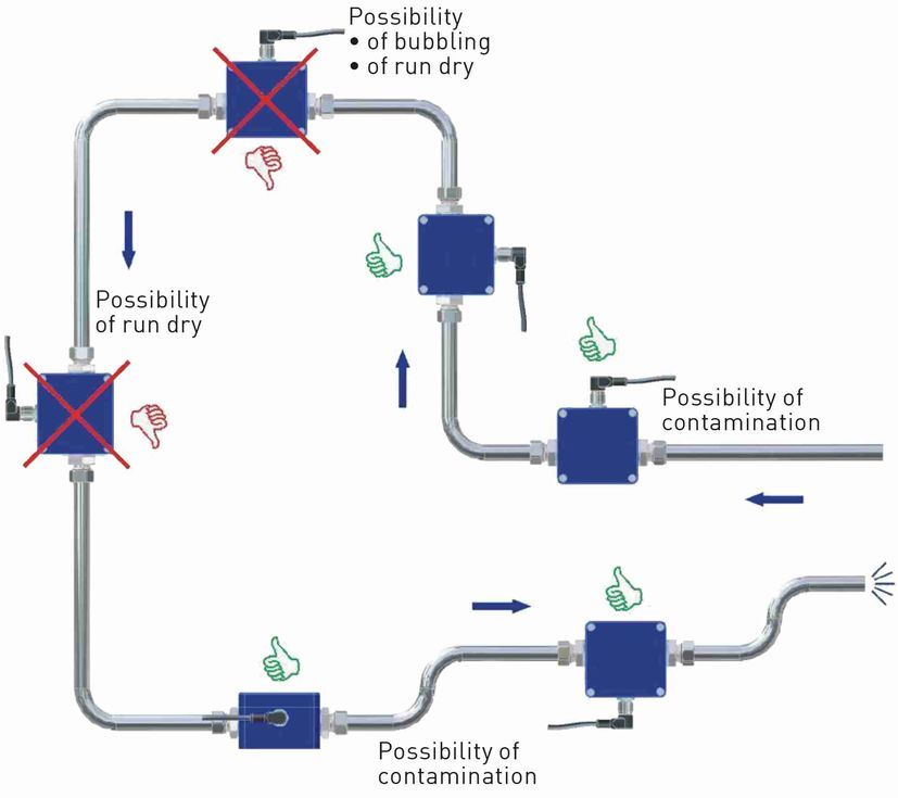
Gerätebeschreibung — Baureihe VMI
2 Gerätebeschreibung
Der der Baureihe VMI von SIKA ist ein Durchflusssensor ohne bewegte Teile. Die
Messung erfolgt mittels magnetischer Induktion.
Der VMI dient der Messung oder Dosierung von Wasser und elektrisch leitfähigen Flüssigkei-
ten. Durch die kompakte Bauform und die weitgehende Unabhängigkeit von den Ein- und
Auslaufstrecken ist der VMI vielseitig einsetzbar.
Ausführungen
Der VMI ist in den Nenngrößen DN 2, DN 7, DN 10 und DN 20 verfügbar.
Typenschild
Den Aufkleber des Typenschildes finden Sie auf der Unterseite des VMI.
Es enthält die wichtigsten technischen Daten und das Anschlussbild für den elektrischen An-
schluss.
Auspacken
Packen Sie das Gerät mit Sorgfalt aus, um Schäden zu vermeiden.
Überprüfen Sie die Vollständigkeit der Lieferung anhand des Lieferscheines.
Lieferumfang
1x VMI wie bestellt.
1x Betriebsanleitung.
WICHTIG
Überprüfen Sie anhand des Typenschildes, ob das gelieferte Gerät Ihrer Be-
stellung entspricht.
Kontrollieren Sie insbesondere bei Geräten mit elektrischen Komponenten, ob
die korrekte Spannungsversorgung angegeben ist.
Zubehör
Anschlussleitung mit angespritzter Kupplungsdose
M12x1.
Kupplungsdose M12x1 zum Selbstkonfektionieren.
-6- © SIKA • Ba_VMI • 10/2020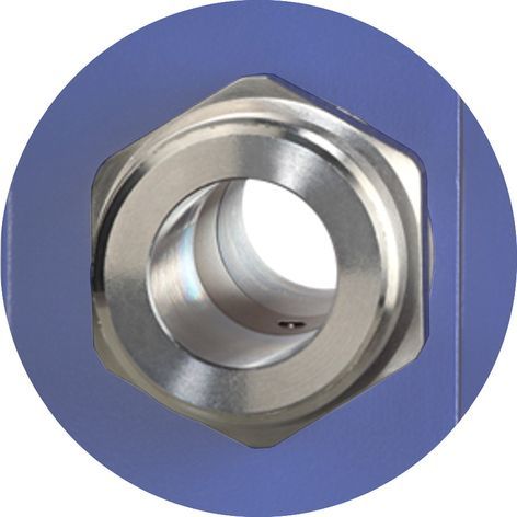
— Baureihe VMI Aufbau und Funktion
3 Aufbau und Funktion
Komponenten
Gehäuse.
Elektrischer Anschluss:
Der elektrische Anschluss erfolgt über einen
5-Pin-Stecker M12x1.
LED für Betriebs- / Durchflussanzeige.
Prozessanschluss:
Die Prozessanschlüsse sind in verschiede-
nen Größen lieferbar.
Typenschild (Aufkleber).
Aufbau
Das Messrohr mit den Erdungshülsen und den Elektroden verläuft
durch das Gehäuse und bildet außen die Prozessanschlüsse des VMI.
Im Inneren des Gehäuses wird das Magnetfeld für die Messung er-
zeugt. Ferner befinden sich dort die Mess- und Auswerteelektronik.
Die beiden Elektroden aus Edelstahl befinden sich in der Mitte des
Messrohres zwischen den Erdungshülsen.
Der VMI benötigt für den Messvorgang keine beweglichen Teile. Das
Innere des Messrohres ist komplett frei. Die Flüssigkeit kann ohne
Hindernisse durch das Messrohr fließen.
Funktion
Der magnetisch induktive Durchflusssensor arbeitet nach dem Induktionsprinzip, d. h., durch
die Bewegung eines Leiters in einem Magnetfeld wird eine Gleichspannung erzeugt:
Das Messrohr des VMI befindet sich in einem Magnet-
feld (B).
Eine elektrisch leitfähige Flüssigkeit (Q) fließt durch das
Messrohr. Dabei werden die positiven und negativen
Ladungsträger entgegengesetzt abgelenkt.
Es entsteht eine Spannung senkrecht zum Magnetfeld,
die durch die beiden Elektroden abgegriffen wird.
Die dabei induzierte Spannung ist proportional zur mitt-
leren Strömungsgeschwindigkeit der Flüssigkeit.
Die Elektronik des VMI wandelt die induzierte Spannung in ein durchflussproportionales Fre-
quenzsignal um.
Technische Änderungen vorbehalten -7-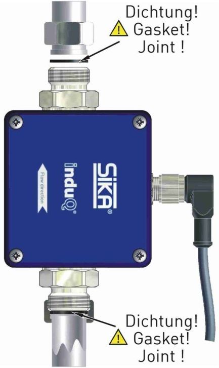
Einbau des VMI — Baureihe VMI
4 Einbau des VMI
Überprüfen Sie vor dem Einbau, ob
die benetzten Werkstoffe des Gerätes für die verwendete Flüssigkeit geeignet sind
( § 9.2 "Werkstofftabelle").
die Anlage ausgeschaltet ist und sich in einem sicheren und stromlosen Zustand befindet.
die Anlage drucklos und abgekühlt ist.
4.1 Einbauhinweise
FEHLFUNKTION DURCH FREMDFELDER
Magnetische Fremdfelder in unmittelbarer Nähe des Gerätes
können zu Fehlfunktionen führen und müssen verhindert wer-
den.
Stellen Sie sicher, dass sich keine Fremdfelder am Ein-
bauort des VMI befinden.
• Der VMI kann prinzipiell an jeder Stelle der Rohrleitung eingebaut werden. Gerade Rohr-
abschnitte sind zu bevorzugen.
-8- © SIKA • Ba_VMI • 10/2020
— Baureihe VMI Einbau des VMI
• Der Einbau kann sowohl in horizontalen, als auch in vertikalen Rohrleitungen erfolgen.
Der Durchflusssensor ist ausschließlich für den Einsatz in komplett gefüllten Leitungen
geeignet.
• Prinzip bedingt sind magnetisch induktive Durchflusssensoren weitgehend unabhängig
vom Strömungsprofil. Eine Beruhigungsstrecke ist nicht zwingend erforderlich.
Um jedoch die höchstmögliche Messgenauigkeit zu erreichen, sollten gerade Ein- und
Auslaufstrecken der entsprechenden Nennweite (DN) verwendet werden. Die Einlauf-
strecke sollte dabei mindestens 10 x DN, das Auslaufrohr 5 x DN lang sein.
• Die Ein- und Auslaufstrecken, sowie die Dichtungen, müssen denselben oder einen ge-
ringfügig größeren Innendurchmesser als das Messrohr aufweisen, um die spezifizierte
Genauigkeit zu erreichen.
4.2 Montage
Der VMI wird direkt in die Rohrleitung eingebaut. Durch die kompakte Bauform und das ge-
ringe Gewicht ist eine Wandmontage nicht erforderlich.
WICHTIG
• Verwenden Sie beim Einbau nur geeignete Dich-
tungen.
• Beachten Sie die Durchflussrichtung auf dem VMI.
• Beachten Sie die Einbaumaße
( § 9.4 "Abmessungen").
Wählen Sie einen geeigneten Einbauort aus
( § 4.1 "Einbauhinweise").
Für eine bestmögliche Messgenauigkeit ist die senkrechte
Einbaulage bei steigender Strömung zu bevorzugen (keine
Schmutzablagerungen).
Installieren Sie passende Anschlussverschraubungen am
Einbauort.
Setzen Sie den VMI zusammen mit den Dichtungen ein.
Schrauben Sie die Überwurfmuttern der Anschlussverschrau-
bung auf die Prozessanschlüsse des VMI.
MAXIMALES DREHMOMENT BEACHTEN
Beim Anziehen der Überwurfmuttern am Sechskant
des Prozessanschlusses gegenhalten!
Ohne Gegenhalten kann der VMI beschädigt werden!
Maximales Drehmoment
VMI02 — G¼ VMI07 — G½ VMI10 — G½ • G¾ VMI20 — G1
8 Nm 15 Nm 15 Nm 30 Nm
Ziehen Sie die beiden Überwurfmuttern fest.
Halten Sie dabei mit einem Gabelschlüssel am Sechskant
des Prozessanschlusses gegen.
Technische Änderungen vorbehalten -9-
Elektrischer Anschluss — Baureihe VMI
5 Elektrischer Anschluss
Der elektrische Anschluss des VMI erfolgt über den 5-Pin-Stecker M12x1 auf der Oberseite
des Gehäuses.
Die Beschaltung des VMI ist abhängig von der bestellten Ausführung. Es wird unterschieden
zwischen Frequenz- und Analogausgang, sowie grundlegender und optionaler Beschaltung.
VORSICHT
Der elektrische Anschluss des VMI darf nur von einer Elektrofachkraft vorgenommen
werden.
Schalten Sie die elektrische Anlage spannungsfrei, bevor Sie den VMI an-
schließen.
BRANDGEFAHR DURCH ÜBERHITZUNG DES GERÄTES
Die Überschreitung der angegebenen Grenzwerte führt zu Schäden an der Elektro-
nik. Ohne Strombegrenzung besteht Brandgefahr durch Überhitzung des Gerätes.
Schließen Sie den VMI nur an eine Stromquelle mit begrenzter Leistung an.
BEI VERWENDUNG AUF SCHIFFEN UND ANDERER
SCHIFFSAUSRÜSTUNG
induQ / VMI-Geräte bieten keine Isolation zwischen Gehäusemasse (FG/PE) und
Signalmasse (GND/0V).
Die 24-VDC-Stromversorgung muss über einen Stromkreis mit Sicherheitsklein-
spannung (SELV) und begrenzter Energie oder SELV und Gleichstromversorgung
der Klasse II (doppelt isoliert) erfolgen. Die von unserem Gerät kommenden Impuls-
und Stromsignale dürfen nur an galvanisch isolierte Eingangsanschlüsse ange-
schlossen werden.
Optionale Beschaltungen
Je nach Ausführung kann optional ein Analogausgang beschaltet werden.
Anschlussleitung
Passende Anschlussleitungen mit angespritzter Kupplungsdose M12x1 sind in unterschiedli-
chen Längen als SIKA-Zubehör erhältlich. Die Abschirmung ist bereits mit der Rändelmutter
verbunden. Die Anschlussleitung darf maximal 30 m lang sein.
ABSCHIRMUNG ERFORDERLICH
Verwenden Sie nur geschirmte An-
schlussleitungen.
Der Schirm der Anschlussleitung sollte
nicht auf Potential Erde gelegt werden.
Eine Erdung der Rohrleitung direkt vor und hinter dem
VMI wird empfohlen ( Abbildung).
- 10 - © SIKA • Ba_VMI • 10/2020— Baureihe VMI Elektrischer Anschluss
WICHTIG
Beachten Sie die Temperaturbeständigkeit der Anschlussleitung
( § 9 "Technische Daten") bei hohen Mediumstemperaturen.
Ist die Temperaturbeständigkeit kleiner als die Mediumstemperatur darf die Leitung
nicht direkt am Rohr verlegt werden.
Anschluss 5-Pin-Stecker M12x1
Schrauben Sie die Kupplungsdose der Anschlussleitung auf den Stecker des VMI.
Ziehen Sie die Rändelmutter der Kupplungsdose mit einem Anzugsmoment von max.
1 Nm fest.
Technische Änderungen vorbehalten - 11 -Elektrischer Anschluss — Baureihe VMI
5.1 Beschaltungen
Pinbelegung
Die Pinbelegung unterscheidet sich je nach gewählter Konfiguration des Gerätes.
Mögliche Belegungen der Pins:
Pin 1: +UB
Pin 2: d. n. c. (nicht beschalten) / Analog U/I
Pin 3: GND
Pin 4: Frequenz
M12x1 Pin 5: n.c. (nicht belegt)
Beschalten Sie die Anschlussleitungen entsprechend ihrer Ausführung und der Pinbele-
gung auf dem Typenschild.
Versorgungsspannung
VMI mit Frequenzausgang
Push-Pull (Gegentakt) NPN Open Collector PNP Open Collector
*1: Push-Pull (Gegentakt) Schaltausgänge mehrerer VMI dürfen nicht parallel geschaltet werden.
*2: Empfehlung Pull-Up / Pull-Down Widerstand RL ~5 kΩ.
Nutzung von Frequenz- und Analogausgang
Push-Pull (Gegentakt) NPN Open Collector PNP Open Collector
Empfehlung für Widerstand RL ~5 kΩ
- 12 - © SIKA • Ba_VMI • 10/2020— Baureihe VMI Inbetriebnahme und Messbetrieb 6 Inbetriebnahme und Messbetrieb Beachten Sie vor dem erstmaligen Einschalten des VMI die Anweisungen des nachfolgenden Abschnittes. 6.1 Inbetriebnahme Überprüfen Sie, ob der VMI richtig eingebaut wurde und alle Verschraubungen dicht sind. die elektrischen Anschlüsse ordnungsgemäß durchgeführt wurden. das Messsystem durch Spülen entlüftet ist. 6.2 Ein- und Ausschalten Der VMI hat keinen Schalter und kann nicht eigenständig ein- oder ausgeschaltet werden. Das Ein- und Ausschalten erfolgt über die angeschlossene Versorgungsspannung. Schalten Sie die Versorgungsspannung ein. Die grüne LED leuchtet einmal für ~1 s auf. Der VMI ist betriebs- bereit und geht in den Messbetrieb über. 6.3 Messbetrieb Im Messbetrieb blinkt die grüne LED proportional zum gemessenen Durchfluss. Für das menschliche Auge ist das Blinken ab einer Frequenz von ~30…40 Hz nicht mehr erkennbar. Die grüne LED scheint dann dauerhaft zu leuchten. Die nachfolgenden Unterpunkte beziehen sich nur auf Geräte, die über die entsprechenden Funktionen verfügen. VMI mit Frequenzausgang Der VMI liefert je nach Ausführung ein durch- flussproportionales NPN-, PNP- oder Push- Pull Rechtecksignal. Die Frequenz des Pulsausganges ändert sich entsprechend dem Durchfluss ( Abb.). Technische Änderungen vorbehalten - 13 -
Wartung und Reinigung — Baureihe VMI
VMI mit Analogausgang
Je nach Konfiguration des VMI liefert der
Analogausgang ein Spannungs- oder
Stromsignal.
Dies ist proportional zum gemessenen
Durchfluss.
7 Wartung und Reinigung
Wartung
Der VMI ist wartungsfrei und kann auch nicht vom Anwender repariert werden. Bei einem De-
fekt muss das Gerät ausgetauscht oder zur Reparatur an den Hersteller zurückgeschickt
werden.
WICHTIG
Beim Öffnen des Gerätes können wichtige Bauteile oder Komponenten beschädigt
werden.
Öffnen Sie niemals das Gerät und führen Sie keine Reparaturen selbst daran
durch.
Reinigung
Reinigen Sie den VMI mit einem trockenen oder leicht angefeuchteten, fusselfreien Tuch.
Verwenden Sie keine scharfen Gegenstände oder aggressive Reinigungsmittel beim Reini-
gen.
7.1 Rücksendung an den Hersteller
Beachten Sie die Hinweise zum Ablauf des Rücksendeverfahrens auf unserer Website
(www.sika.net/services/warenrücksendung-rma.html).
- 14 - © SIKA • Ba_VMI • 10/2020— Baureihe VMI Demontage und Entsorgung
8 Demontage und Entsorgung
VORSICHT
Entfernen Sie niemals das Gerät aus einer im Betrieb befindlichen Anlage.
Sorgen Sie dafür, dass die Anlage fachgerecht ausgeschaltet wird.
Vor der Demontage
Überprüfen Sie vor der Demontage, ob
die Anlage ausgeschaltet ist und sich in einem sicheren und stromlosen Zustand befindet.
die Anlage drucklos und abgekühlt ist.
Demontage
Entfernen Sie die elektrischen Anschlüsse.
Bauen Sie den VMI mit passenden Werkzeugen aus.
Entsorgung
Konform zu den Richtlinien 2011/65/EU (RoHS) und 2012/19/EU (WEEE)* muss das Gerät
separat als Elektro- und Elektronikschrott entsorgt werden.
KEIN HAUSMÜLL
Das Gerät besteht aus unterschiedlichen Werkstoffen. Es darf nicht zusammen mit
Hausmüll entsorgt werden.
Führen Sie das Gerät der lokalen Wiederverwertung zu
oder
schicken Sie das Gerät zur Entsorgung an Ihren Lieferanten bzw. SIKA zurück.
* WEEE-Reg.-Nr.: DE 25976360
Technische Änderungen vorbehalten - 15 -Technische Daten — Baureihe VMI
9 Technische Daten
Bei kundenspezifischen Ausführungen können technische Daten gegenüber den Angaben
dieser Anleitung abweichen. Bitte beachten Sie die Angaben auf dem Typenschild.
9.1 Kenndaten VMI
Typ VMI02 VMI07 VMI10 VMI20
Kenndaten Messgerät
Messbereich 0,0083...1 l/min • 0,5…30 l/min 1…60 l/min 5…250 l/min
0,05...2 l/min
Messgenauigkeit *1 ±1 % v. Messbe- ±1,5% v. Messwert ±0,3% v. Messbereichsendwert
(Frequenzausgang) reichsendwert *2 •
±2 % v. Messbe-
reichsendwert *3
Wiederholbarkeit *1 1%
Signalabgabe ab 0,0083...1 l/min • ~0,4 l/min ~0,9 l/min ~4 l/min
0,05...2 l/min
Reaktionszeit < 500 ms
(Frequenz / Frequenz +
Analog)
Durchflussanzeige LED grün, blinkt durchflussproportional
Kenndaten Ausgangssignal
Frequenzausgang
Pulsrate 10000 Pulse/l 1000 Pulse/l 500 Pulse/l 100 Pulse/l
- optional *4 1…2000 Pulse/l 1…1000 Pulse/l 1…200 Pulse/l
Auflösung 0,1 ml/Puls 1,0 ml/Puls 2,0 ml/Puls 10 ml/Puls
- optional *4 1000…0,5 1000…1 ml/Puls 1000…5 ml/Puls
ml/Puls
Signalform Rechtecksignal • Tastverhältnis 50:50
Push-Pull (Gegentakt) • NPN open collector (o.c.) • PNP o.c.
Signalstrom ≤ 100 mA, strombegrenzt
Analogausgang 4…20 mA (optional)
Signalstrom entspricht 0...1 l/min • 0…20 l/min 0…40 l/min 0…200 l/min
Durchfluss von 0...2 l/min • 0…30 l/min • 0…60 l/min • 0…250 l/min
max. Bürde 250 Ω gegen GND
Analogausgang 0…10 V (optional)
Signalspannung ent- 0...1 l/min • 0…20 l/min 0…40 l/min 0…200 l/min
spricht Durchfluss von 0...2 l/min • 0…30 l/min • 0…60 l/min • 0…250 l/min
*1 Prüfbedingungen: Wasser 23 °C bei 150 ±100 µS/cm; Standardpulsrate.
*2 0...50 % vom Messbereich.
*3 50…100 % vom Messbereich.
*4 werkseitig konfigurierbar.
- 16 - © SIKA • Ba_VMI • 10/2020— Baureihe VMI Technische Daten
Typ VMI02 VMI07 VMI10 VMI20
Elektrische Kenndaten
Versorgungs- 12…24 VDC ±10% 24 VDC ±10%
spannung
Stromaufnahme ≤ 150 mA
Elektrischer An- 5-Pin-Stecker M12x1
schluss
Schutzart IP 65 und IP67 (mit aufgesteckter Kupplungsdose)
(DIN EN 60529)
Prozessgrößen
Messmedium: Wasser und andere leitfähige Flüssigkeiten
- Leitfähigkeit > 50 μS/cm
- Temperatur -20…90 °C
Umgebungs- -10…Tmax °C ( § 9.3)*
temperatur
Nennweite DN 2 DN 7 DN 10 DN 20
Nenndruck PN 16
Prozessan- G¼-ISO 228 au-G½ - ISO 228 au- G½ - ISO 228 außen G1 - ISO 228 au-
schluss ßen ßen • G¾ - ISO 228 ßen
außen
* Die maximale Umgebungstemperatur ist abhängig von der Temperatur des Mediums und der Be-
schaltung des VMIs.
9.2 Werkstofftabelle
Bauteil Werkstoff Bauteil benetzt
Gehäuse Aluminium Druckguss
Messrohr PEEK-GF30 X
Elektroden Edelstahl 1.4571 X
Dichtungen EPDM • FKM (optional) X
Prozessanschlüsse Edelstahl 1.4571 X
Technische Änderungen vorbehalten - 17 -Technische Daten — Baureihe VMI
9.3 Temperatureinsatzgrenzen
Die maximale Umgebungstemperatur ist abhängig von der Temperatur des Mediums und der
Ausführung des VMIs.
80
Obergrenze Frequenzausgang
70
60
Frequenz-
50
und Analogausgang
Umgebung [°C] .
40
30
20
10
0
-10
Untergrenze
-20
-20 -10 0 10 20 30 40 50 60 70 80 90
Medium [°C]
- 18 - © SIKA • Ba_VMI • 10/2020— Baureihe VMI Technische Daten
9.4 Abmessungen
L1
t
b
c
G
h1
i
d2
h
a
D1
L2 ⎔
Abmessungen aus Zeichnung in mm
VMI L1 ±0,5 L2 ±0,5 D1 d2 i b h t a c h1
02 120 12 G¼A ⌀3 1,9 80 75 65 34 36 14 17
07 124 12 G½A ⌀10 4 80 75 65 33 36 14 27
10 124 12 G¾A ⌀10 -/- 80 75 65 33 36 14 27
20 140 18 G1A ⌀20 -/- 80 75 65 33,5 36 14 36
Technische Änderungen vorbehalten - 19 -SIKA Dr. Siebert & Kühn GmbH & Co. KG Struthweg 7–9 34260 Kaufungen / Germany Tel: +49 5605 803-0 Fax: +49 5605 803-555 info@sika.net www.sika.net © SIKA • Ba_VMI • 10/2020
Operating manual
                               Betriebsanleitung .................................................. Seite 1 - 20
                               Operating manual ................................................page 21 - 40
                               Notice d'utilisation ................................................page 41 - 60

                              Magnetic inductive flow sensor
                              Series VMI
                              Types VMI02 • VMI07 • VMI10 • VMI20
© SIKA • Ba_VMI • 10/2020 :

                              Please keep this operating manual for future reference.
                              If the device is resold, please provide the operating manual along with it.
— Series VMI
Table of contents page
0 About this operating manual.................................................................................... 23
1 Safety instructions ................................................................................................... 24
2 Device description ................................................................................................... 26
3 Construction and function........................................................................................ 27
4 Installation of VMI.................................................................................................... 28
4.1 Installation instructions .......................................................................................... 28
4.2 Mounting ............................................................................................................... 29
5 Electrical connection ............................................................................................... 30
5.1 Wirings .................................................................................................................. 32
6 Commissioning and measuring mode ..................................................................... 33
6.1 Commissioning ..................................................................................................... 33
6.2 Switching on and off .............................................................................................. 33
6.3 Measuring mode ................................................................................................... 33
7 Maintenance and cleaning ...................................................................................... 34
7.1 Return shipment to the manufacturer .................................................................... 34
8 Disassembly and disposal ....................................................................................... 35
9 Technical data ......................................................................................................... 36
9.1 Characteristics VMI ............................................................................................... 36
9.2 Materials table ....................................................................................................... 37
9.3 Temperature limits ................................................................................................ 38
9.4 Dimensions ........................................................................................................... 39
is a registered trademark of SIKA Dr. Siebert & Kühn GmbH & Co. KG
Copyright notice
The reproduction, distribution and utilization of this operating manual as well as the communication
of its contents to others without express authorization is prohibited. Offenders will be held liable for
the payment of damages. All rights reserved in the event of the grant of a patent, utility model or de-
sign.
- 22 - © SIKA • Ba_VMI • 10/2020— Series VMI About this operating manual
0 About this operating manual
Symbols used:
WARNING
Failure to do so may result in death or serious injury
CAUTION
Failure to do so may result in minor or moderate injury.
IMPORTANT
Failure to do so may result in damage to property and the environment.
If you have any problems or questions, please contact your supplier or contact us directly at:
SIKA Dr. Siebert & Kühn GmbH & Co. KG
Struthweg 7–9
34260 Kaufungen / Germany
+49 5605 803-0
+49 5605 803-555
info@sika.net
www.sika.net
Exclusion of liability
We accept no liability for any damage or malfunctions resulting from incorrect installation, inappropri-
ate use of the device or failure to follow the instructions in this operating manual.
Technical changes reserved - 23 -Safety instructions — Series VMI
1 Safety instructions
Before you install the device, read through this operating manual carefully. If the instructions con-
tained within it are not followed, in particular the safety guidelines, this could result in danger for
people, the environment, and the device and the system it is connected to.
The device corresponds to the state-of-the-art technology. This concerns the accuracy, the
operating mode and the safe operation of the device.
In order to guarantee that the device operates safely, the operator must act competently and
be conscious of safety issues.
SIKA provides support for the use of its products either personally or via relevant literature.
The customer verifies that our product is fit for purpose based on our technical information.
The customer performs customer- and application-specific tests to ensure that the product is
suitable for the intended use. With this verification all hazards and risks are transferred to our
customers; our warranty is not valid.
Intended use
The magnetic inductive flow sensor VMI must only be used for measuring and metering liq-
uids with a minimum conductivity of 50 μS/cm.
WARNING
The magnetic inductive flow sensors of the VMI series are no safety components in
accordance with Directive 2006/42/EC (Machine Directive).
Never use the device as a safety component.
The operational safety of the device supplied is only guaranteed by intended use. The speci-
fied limits ( § 9 "Technical data") may under no circumstances be exceeded.
Before installation, check whether the wetted materials of the device are suitable for the liquid
used ( § 9.2 "Materials table").
MEASURING TUBE EMPTY (OR PARTIALLY FILLED) /
CONDUCTIVITY TOO LOW
The green LED may blink irregularly if the measuring tube of the VMI is empty or
partially filled or if the conductivity of the fluid being used is too low. Random pulses
will be present at the output, but they do not represent an actual flow.
Ensure that the measuring tube of the VMI is always completely filled
( § 4.1 "Installation instructions").
Ensure that the conductivity of the fluid is at least 50 μS/cm.
- 24 - © SIKA • Ba_VMI • 10/2020— Series VMI Safety instructions
Qualified personnel
• The personnel who are charged for the installation, operation and maintenance of the
VMI must hold a relevant qualification. This can be based on training or relevant tuition.
The personnel must be aware of this operating manual and have access to it at all times.
• The electrical connection should only be carried out by a fully qualified electrician.
General safety instructions
• In all work, the existing national regulations for accident prevention and safety in the
workplace must be complied with. Any internal regulations of the operator must also be
complied with, even if these are not mentioned in this manual.
• Degree of protection according to EN 60529:
Please ensure that the ambient conditions at the site of use does not exceed the re-
quirements for the stated protection rating ( § 9 "Technical data").
• Prevent freezing of the medium in the device with appropriate measures.
• Only use the VMI if it is in perfect condition. Damaged or faulty devices must be checked
without delay and, if necessary, replaced.
• When fitting, connecting and removing the VMI use only suitable appropriate tools.
• Do not remove or obliterate type plates or other markings on the device, as otherwise the
warranty is rendered null and void.
Technical changes reserved - 25 -Device description — Series VMI
2 Device description
The of the VMI series from SIKA is a flow sensor without moving parts. The meas-
urement is performed using magnetic induction.
The VMI is used for measuring or metering water and electrically conductive fluids. The com-
pact design and independence from the intake and discharge sections allows the VMI to be
used under a variety of conditions.
Versions
The VMI is available in nominal sizes DN 2, DN 7, DN 10 and DN 20.
Type plate
The type plate sticker is located on the bottom side of the VMI.
It contains the most important data, the connection diagram and the arrow for the flow direc-
tion.
Unpacking
Carefully unpack the unit to prevent any damage.
Check the completeness of the delivery based on the delivery note.
Scope of delivery
1x VMI as ordered.
1x Operating manual.
WICHTIG
Use the type plate to check if the delivered unit corresponds to your order.
In particular, for devices with electrical components, check to see if the correct
power supply voltage is specified.
Accessories
Connection cable with moulded M12x1 coupling
socket.
M12x1 coupling socket for self-assembly.
- 26 - © SIKA • Ba_VMI • 10/2020— Series VMI Construction and function
3 Construction and function
Components
Housing.
Electrical connection:
The electrical connection is made via 5-pin
plug M12x1.
Operation / flow indicator LED.
Process connection:
The process connections are available in dif-
ferent sizes.
Type plate (sticker).
Construction
The measuring tube with its earthing sleeves and electrodes passes
through the housing and forms the external process connection of the
VMI.
A magnetic field for the measurement process is generated inside the
sensor housing, which also contains the sensor and signal condition-
ing circuitry.
The two stainless steel electrodes are located in the middle of the
measuring tube between the earthing sleeves.
The VMI does not need any moving parts to make measurements. The inside of the measur-
ing tube is completely open, allowing the fluid to flow unhindered through the measuring tube.
Function
The magnetic inductive flow sensor operates in accordance with the principle of induction, i.e.
a DC voltage is generated by the movement of a conductor in a magnetic field:
The measuring tube of the VMI is located in a magnetic
field (B).
An electrically conductive liquid (Q) flows through the
measuring tube. The positive and negative charge car-
riers are deflected in opposite directions.
A voltage perpendicular to the magnet field is generat-
ed and picked up by the two electrodes.
The resulting induced voltage is proportional to the
mean flow velocity of the liquid.
The electronics of the VMI converts the induced voltage to a flow-proportional frequency sig-
nal.
Technical changes reserved - 27 -Installation of VMI — Series VMI
4 Installation of VMI
Before installing, check that
the wetted materials of the device are suitable for the liquid being used
( § 9.2 "Materials table").
the equipment is switched off and is in a safe and de-energised state.
the equipment is depressurised and has cooled down.
4.1 Installation instructions
RISK OF MALFUNCTION DUE TO EXTERNAL
MAGNETIC FIELDS
Magnetic fields close to the device can cause malfunctions and
should be avoided.
Ensure that no external magnetic fields are present at the
installation site of the VMI.
• The VMI can always be installed anywhere along the pipeline. Straight sections of piping
are preferable, however.
- 28 - © SIKA • Ba_VMI • 10/2020— Series VMI Installation of VMI
• Installation can occur in horizontal and vertical pipes. The flow sensor is only suitable for
application in completely filled pipe systems.
• As a matter of principle magnetic inductive flow sensors are widely independent from the
flow profile. An inlet section is not absolutely necessary.
To reach a most highly accuracy of the measurement, you should use straight inlet and
outlet sections according to the nominal width (DN). The inlet section has to be at least
10 x DN; the outlet section 5 x DN in order to achieve the specified accuracy.
• The inlet and outlet sections and the gaskets must have the same or a slightly larger in-
side diameter than the measuring tube in order to achieve the specified accuracy.
4.2 Mounting
The VMI is installed directly into the pipeline. The compact design and light weight of the unit
make wall-mounting unnecessary.
IMPORTANT
• Only use suitable gaskets for installation.
• Observe the flow direction indicated on the VMI.
• Observe the mounting dimensions
( § 9.4 "Dimensions").
Select an appropriate location for installation
( § 4.1 "Installation instructions").
To ensure the best possible measuring accuracy, a vertical
installation position with increasing flow is preferable (no col-
lecting of dirt deposits).
Install the appropriate screwed connections at the installation
location.
Insert the VMI together with the gaskets.
Screw the union nuts of the screwed connection onto the pro-
cess connections of the VMI.
PAY ATTENTION TO MAXIMUM TORQUE
While tightening, counter the union nut on the hexa-
gon of the process connection!
If you do not counter it, the VMI can be damaged!
Maximum Torque
VMI02 — G¼ VMI07 — G½ VMI10 — G½ • G¾ VMI20 — G1
8 Nm 15 Nm 15 Nm 30 Nm
Tighten both union nuts.
When tightening, use a spanner to counter the process con-
nection on the hexagon in place.
Technical changes reserved - 29 -Electrical connection — Series VMI
5 Electrical connection
The electrical connection of the VMI is made via the 5-pin plug M12x1 on the top of the hous-
ing.
The wiring of the VMI depends on the version ordered. A distinction is made between fre-
quency and analogue output, as well as basic and optional wiring.
CAUTION
The electrical connection should only be carried out by a fully qualified electrician.
De-energize the electrical system before connecting the VMI.
FIRE HAZARD DUE TO OVERHEATING OF THE DEVICE
Exceeding the specified limits will cause damage to the electronics. Without current
limiting, there is a fire hazard due to overheating of the device.
Connect the VMI only to a power source with limited power.
FOR USE ON SHIPS OR OTHER MARITIME EQUIPMENT
induQ / VMI devices do not offer isolation between Frame Ground (FG/PE) and
Signal Ground (GND/0V).
24 VDC power needs to be supplied via a Safety Extra Low Voltage (SELV) and
Limited Energy Circuit or SELV and Class II (double insulated) DC power supply.
Pulse and current signals coming from our device may only get connected to gal-
vanic insulated input ports.
Optional wirings
Depending on the version, an analogue output can be optionally connected.
Connecting cable
Suitable connection cables with moulded coupling socket are available in various lengths in-
cluded in the range of SIKA accessories. The shielding is already connected with the knurled
nut. The maximum length of the connecting cable is 30 m.
SHIELDING REQUIRED
Use only shielded connection cables.
The shield of the connection cable
should not be connected to earth.
We recommend to earth the pipes directly before and
behind the VMI ( Figure).
- 30 - © SIKA • Ba_VMI • 10/2020— Series VMI Electrical connection
IMPORTANT
Pay attention to the temperature resistance of the connecting cable
( § 9 "Technical data") at high media temperatures.
If the temperature resistance is smaller than the medium temperature, the cable
may not be directly laid on the pipe.
Connection 5-pin plug M12x1
Screw the coupling socket of the connection cable to the plug of the VMI.
Tighten the knurled nut of the coupling socket with a maximum torque of 1 Nm.
Technical changes reserved - 31 -Electrical connection — Series VMI
5.1 Wirings
Pinout
The pinout differs according to the chosen configuration of the device.
Possible pinout:
Pin 1: +UB
Pin 2: d. n. c. (do not connect) / Analogue U/I
Pin 3: GND
Pin 4: Frequency
M12x1 Pin 5: n. c. (not connected)
Connect the connecting cable according to your version and the pinout on the type plate.
Supply voltage
VMI with frequency output
Push-Pull NPN Open Collector PNP Open Collector
*1: Push-Pull switching outputs of several VMI may not be connected in parallel.
*2: Recommendation Pull-Up / Pull-Down resistance RL ~5 kΩ
Use of frequency and analogue output
Push-Pull NPN Open Collector PNP Open Collector
Recommendation for resistance RL ~5 kΩ
- 32 - © SIKA • Ba_VMI • 10/2020— Series VMI Commissioning and measuring mode 6 Commissioning and measuring mode Before switching on the VMI for the first time, please follow the instructions in the following section. 6.1 Commissioning Check that the VMI has been installed correctly and that all screw connections are sealed. the electrical wiring has been connected properly. the measuring system is vented by flushing. 6.2 Switching on and off The VMI has no switch and can therefore not be switched on and off independently. Switch- ing on and off takes place via the connected supply voltage. Switch on the supply voltage. The green LED lights up once for~1 s. The VMI is ready and goes into measuring mode. 6.3 Measuring mode In measuring mode, the green LED flashes proportional to the measured flow. The human eye cannot detect the flashing any longer from a fre- quency of ~30 ... 40 Hz. In that case the green LED seems to be lit permanently. The following subsections only apply to devices which have the correspondent functionality. VMI with frequency output The VMI provides according to the version a flow pro- portional NPN, PNP or Push-Pull square wave signal. The frequency of the pulse output changes according to the flow ( Fig.). Technical changes reserved - 33 -
Maintenance and cleaning — Series VMI
VMI with analogue output
According to the configuration of the VMI,
the analogue output provides a voltage or
current signal.
This signal is proportional to the measured
flow.
7 Maintenance and cleaning
Maintenance
The VMI is maintenance-free and cannot be repaired by the user. In case of a defect, the de-
vice must be replaced or sent back the manufacturer for repair.
IMPORTANT
When opening the device, critical parts or components can be damage.
Never open the device and perform any repair yourself.
Cleaning
Clean the VMI with a dry or slightly damp lint-free cloth. Do not use sharp objects or aggres-
sive agents for cleaning.
7.1 Return shipment to the manufacturer
Please follow the instructions on the procedure for sending returns which are on our
website (www.sika.net/en/services/return-of-products-rma.html).
- 34 - © SIKA • Ba_VMI • 10/2020— Series VMI Disassembly and disposal
8 Disassembly and disposal
CAUTION
Never remove the device from a plant in operation.
Make sure that the plant is shut down professionally.
Before disassembly
Prior to disassembly, ensure that
the equipment is switched off and is in a safe and de-energised state.
the equipment is depressurised and has cooled down.
Disassembly
Remove the electrical connectors.
Remove the VMI using suitable tools.
Disposal
Compliant with the Directives 2011/65/EU (RoHS) and 2012/19/EU (WEEE)*, the device
must be disposed of separately as electrical and electronic waste.
NO HOUSEHOLD WASTE
The VMI consists of various different materials. It must not be disposed of with
household waste.
Take the device to your local recycling plant
or
send the device back to your supplier or to SIKA.
* WEEE reg. no.: DE 25976360
Technical changes reserved - 35 -Technical data — Series VMI
9 Technical data
The technical data of customised versions may differ from the data in these instructions.
Please observe the information specified on the type plate.
9.1 Characteristics VMI
Type VMI02 VMI07 VMI10 VMI20
Measurement device characteristics
Measuring range 0.0083...1 l/min • 0.5…30 l/min 1…60 l/min 5…250 l/min
0.05...2 l/min
Accuracy *1 ±1 % of full scale ±1.5% of reading ±0.3% of full scale value
(Frequency output) value *2 •
±2 % of full scale
value *3
Repeatability *1 1%
Signal output from 0.0083...1 l/min • ~0.4 l/min ~0.9 l/min ~4 l/min
0.05...2 l/min
Response time < 500 ms
(Frequency / Frequency +
Analogue)
Flow indication LED green, flow proportional flashing
Output signal characteristics
Frequency output:
Pulse rate 10000 pulses/l 1000 pulses/l 500 pulses/l 100 pulses/l
- pptional *4 1…2000 pulse/l 1…1000 pulse/l 1…200 pulse/l
Resolution 0.1 ml/pulse 1.0 ml/pulse 2.0 ml/pulse 10 ml/pulse
- optional *4 1000…0.5 1000…1 ml/pulse 1000…5 ml/pulse
ml/pulse
Signal shape Square wave signal • duty cycle 50:50
Push-Pull • NPN open collector (o.c.) • PNP o.c.
Signal current ≤ 100 mA, current limited
Analogue output 4…20 mA (optional):
Signal current corre- 0...1 l/min • 0…20 l/min 0…40 l/min 0…200 l/min
sponds to flow rate of 0...2 l/min • 0…30 l/min • 0…60 l/min • 0…250 l/min
Max. load 250 Ω to GND
Analogue output 0…10 V (optional):
Signal voltage corre- 0...1 l/min • 0…20 l/min 0…40 l/min 0…200 l/min
sponds to flow rate of 0...2 l/min • 0…30 l/min • 0…60 l/min • 0…250 l/min
*1 Test conditions: Water 23 °C at 150 ±100 µS/cm; Standard pulse rate.
*2 0...50 % of measuring range.
*3 50…100 % of measuring range.
*4 factory setting.
- 36 - © SIKA • Ba_VMI • 10/2020— Series VMI Technical data
Type VMI02 VMI07 VMI10 VMI20
Electrical characteristics
Supply voltage 12…24 VDC ±10% 24 VDC ±10%
Current consumption ≤ 150 mA
Electrical connection 5-pin-plug M12x1
Degree of protection IP 65 and IP67 (with attached coupling socket)
(EN 60529)
Process variables
Medium to measure: Water and other conductive liquids
- Conductivity > 50 μS/cm
- Temperature -20…90 °C
Ambient temperature -10…Tmax °C ( § 9.3)*
Nominal diameter DN 2 DN 7 DN 10 DN 20
Nominal pressure PN 16
Process connection G¼-ISO 228 male G½ - ISO 228 G½ - ISO 228 male G1 - ISO 228
male • G¾ - ISO 228 male
male
* The maximum ambient temperature depends on the temperature of the medium and the wiring of
the VMI.
9.2 Materials table
Wetted
Component Material component
Housing Aluminium die casting
Measuring tube PEEK-GF30 X
Electrodes Stainless steel 1.4571 X
Gaskets EPDM • FKM (optional) X
Process connections Stainless steel 1.4571 X
Technical changes reserved - 37 -Technical data — Series VMI
9.3 Temperature limits
The maximum ambient temperature depends on the medium temperature and the version of
the VMI.
80
Upper limit Frequency output
70
60
Frequency
50
and analogue output
Ambient [°C] .
40
30
20
10
0
-10
Lower limit
-20
-20 -10 0 10 20 30 40 50 60 70 80 90
Medium [°C]
- 38 - © SIKA • Ba_VMI • 10/2020— Series VMI Technical data
9.4 Dimensions
L1
t
b
c
G
h1
i
d2
h
a
D1
L2 ⎔
Dimensions from drawing in mm
VMI L1 ±0,5 L2 ±0,5 D1 d2 i b h t a c h1
02 120 12 G¼A ⌀3 1.9 80 75 65 34 36 14 17
07 124 12 G½A ⌀10 4 80 75 65 33 36 14 27
10 124 12 G¾A ⌀10 -/- 80 75 65 33 36 14 27
20 140 18 G1A ⌀20 -/- 80 75 65 33.5 36 14 36
Technical changes reserved - 39 -SIKA Dr. Siebert & Kühn GmbH & Co. KG Struthweg 7–9 34260 Kaufungen / Germany Tel: +49 5605 803-0 Fax: +49 5605 803-555 info@sika.net www.sika.net © SIKA • Ba_VMI • 10/2020
Notice d'utilisation
                               Betriebsanleitung .................................................. Seite 1 - 20
                               Operating manual ................................................page 21 - 40
                               Notice d'utilisation ................................................page 41 - 60

                              Débitmètre à induction magnétique
                              Séries VMI
                              Types VMI02 • VMI07 • VMI10 • VMI20
© SIKA • Ba_VMI • 10/2020 :

                              Conservez cette notice d'utilisation pour vous y reporter.
                              Joignez cette notice d'utilisation à la vente de l'appareil.
— Séries VMI
Sommaire page
0 Indications sur la notice d'utilisation ........................................................................ 43
1 Consignes de sécurité ............................................................................................. 44
2 Description de l'appareil .......................................................................................... 46
3 Construction et fonction .......................................................................................... 47
4 Montage du VMI ...................................................................................................... 48
4.1 Instructions de montage ........................................................................................ 48
4.2 Montage ................................................................................................................ 49
5 Raccordement électrique ........................................................................................ 50
5.1 Câblages ............................................................................................................... 52
6 Mise en service et mode mesure ............................................................................ 53
6.1 Mise en service ..................................................................................................... 53
6.2 Allumer et éteindre ................................................................................................ 53
6.3 Mode mesure ........................................................................................................ 53
7 Entretien et nettoyage ............................................................................................. 54
7.1 Retour au fabricant ............................................................................................... 54
8 Démontage et Élimination ....................................................................................... 55
9 Données techniques ............................................................................................... 56
9.1 Caractéristiques VMI ............................................................................................. 56
9.2 Tableau des matériaux.......................................................................................... 57
9.3 Limites de température ......................................................................................... 58
9.4 Dimensions ........................................................................................................... 59
est une marque déposée de SIKA Dr. Siebert & Kühn GmbH & Co. KG.
Note sur la protection des droits d'auteur
Toute communication ou reproduction de cette notice d'utilisation, toute exploitation ou communication
de son contenu sont interdites, sauf autorisation expresse. Tout manquement à cette règle est illicite
et expose son auteur au versement de dommages et intérêts. Tous droits réservés pour le cas de la
délivrance d'un brevet, d'un modèle d'utilité ou d'un modèle de présentation.
- 42 - © SIKA • Ba_VMI • 10/2020— Séries VMI Indications sur la notice d'utilisation
0 Indications sur la notice d'utilisation
Symboles utilisés :
AVERTISSEMENT
Le non-respect de cette instruction peut entraîner la mort ou des blessures graves.
ATTENTION
Le non-respect de cette instruction peut entraîner des blessures mineures ou modérées.
IMPORTANT
Le non-respect de cette instruction peut entraîner des dommages matériels et environ-
nementaux.
Si vous avez des problèmes ou des questions, adressez-vous à votre fournisseur ou direc-
tement à :
SIKA Dr. Siebert & Kühn GmbH & Co. KG
Struthweg 7–9
34260 Kaufungen / Germany
+49 5605 803-0
+49 5605 803-555
info@sika.net
www.sika.net
Exclusion de garantie
Aucune garantie n'est assurée pour ce qui concerne les dommages et les incidents d'exploitation, ré-
sultant d'erreurs de montage, d'une utilisation non-conforme ou d'un non-respect de ce mode d'em-
ploi.
Sous réserve de modifications techniques - 43 -Sie können auch lesen