Seillängengeber - Montage- und - tr-electronic.de
←
→
Transkription von Seiteninhalten
Wenn Ihr Browser die Seite nicht korrekt rendert, bitte, lesen Sie den Inhalt der Seite unten
D    Seite 2 - 20

                                      GB   Page 21 - 40

  Seillängengeber

                                                          TR-ECE-BA-DGB-0170 v00 04/04/2022

_Grundlegende Sicherheitshinweise
_Verwendungszweck
_Allgemeine Funktionsbeschreibung

_Montagehinweise

                                      Montage- und
                                    Betriebsanleitung
TR-Electronic GmbH
D-78647 Trossingen
Eglishalde 6
Tel.: (0049) 07425/228-0
Fax: (0049) 07425/228-33
E-mail: info@tr-electronic.de
www.tr-electronic.de
Urheberrechtsschutz
Dieses Handbuch, einschließlich den darin enthaltenen Abbildungen, ist
urheberrechtlich geschützt. Drittanwendungen dieses Handbuchs, welche von den
urheberrechtlichen Bestimmungen abweichen, sind verboten. Die Reproduktion,
Übersetzung sowie die elektronische und fotografische Archivierung und
Veränderung bedarf der schriftlichen Genehmigung durch den Hersteller.
Zuwiderhandlungen verpflichten zu Schadenersatz.
Änderungsvorbehalt
Jegliche Änderungen, die dem technischen Fortschritt dienen, vorbehalten.
Dokumenteninformation
Ausgabe-/Rev.-Datum: 04/04/2022
Dokument-/Rev.-Nr.: TR-ECE-BA-DGB-0170 v00
Dateiname: TR-ECE-BA-DGB-0170-00.docx
Verfasser: STB
Schreibweisen
Kursive oder fette Schreibweise steht für den Titel eines Dokuments oder wird zur
Hervorhebung benutzt.
Courier-Schrift zeigt Text an, der auf dem Display bzw. Bildschirm sichtbar ist und
Menüauswahlen von Software.
< > weist auf Tasten der Tastatur Ihres Computers hin (wie etwa ).
TR-Electronic GmbH 2022, All Rights Reserved Printed in the Federal Republic of Germany
Page 2 of 40 TR-ECE-BA-DGB-0170 v00 04/04/2022
Inhaltsverzeichnis
Inhaltsverzeichnis .............................................................................................................................. 3
Änderungs-Index ................................................................................................................................ 4
1 Allgemeines ..................................................................................................................................... 5
1.1 Geltungsbereich ...................................................................................................................... 5
1.2 Mitgeltende Dokumente .......................................................................................................... 5
1.3 EU-Konformitätserklärung ...................................................................................................... 6
1.4 Verwendete Abkürzungen und Begriffe .................................................................................. 6
1.5 Prinzipaufbau .......................................................................................................................... 7
1.6 Messprinzip ............................................................................................................................. 7
2 Grundlegende Sicherheitshinweise .............................................................................................. 8
2.1 Symbol- und Hinweis-Definition .............................................................................................. 8
2.2 Verpflichtung des Betreibers vor der Inbetriebnahme ............................................................ 8
2.2.1 UL / CSA – Zulassung ............................................................................................ 9
2.3 Allgemeine Gefahren bei der Verwendung des Produkts ...................................................... 9
2.4 Bestimmungsgemäße Verwendung ....................................................................................... 10
2.5 Bestimmungswidrige Verwendung ......................................................................................... 10
2.6 Gewährleistung und Haftung .................................................................................................. 10
2.7 Organisatorische Maßnahmen ............................................................................................... 11
2.8 Personalauswahl und -qualifikation; grundsätzliche Pflichten ................................................ 11
2.9 Sicherheitstechnische Hinweise ............................................................................................. 12
3 Transport / Lagerung ...................................................................................................................... 13
4 Montagevorschriften ....................................................................................................................... 14
4.1 Anwendungshinweise ............................................................................................................. 15
4.1.1 Montage .................................................................................................................. 15
4.1.2 Seilabzug ................................................................................................................ 16
4.1.3 Sicherheit ................................................................................................................ 16
5 Montagehinweise / Schema ............................................................................................................ 17
5.1 SL30… .................................................................................................................................... 17
5.1.1 Seilendring mit Kugelgelenk ................................................................................... 17
5.2 SL00… .................................................................................................................................... 18
5.3 WDS… .................................................................................................................................... 18
5.4 WPS… .................................................................................................................................... 19
6 Zubehör ............................................................................................................................................ 20
6.1 SL30… .................................................................................................................................... 20
6.2 WDS… .................................................................................................................................... 20
Printed in the Federal Republic of Germany TR-Electronic GmbH 2022, All Rights Reserved
04/04/2022 TR-ECE-BA-DGB-0170 v00 Page 3 of 40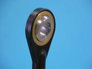
Änderungs-Index Änderungs-Index Änderung Datum Index Erstausgabe 04.04.2022 00 TR-Electronic GmbH 2022, All Rights Reserved Printed in the Federal Republic of Germany Page 4 of 40 TR-ECE-BA-DGB-0170 v00 04/04/2022
1 Allgemeines
Die vorliegende Montageanleitung beinhaltet folgende Themen:
Allgemeine Funktionsbeschreibung
Grundlegende Sicherheitshinweise mit Angabe des Verwendungszwecks
Montagevorschriften
Montagehinweise / Schema
Da die Dokumentation modular aufgebaut ist, stellt diese Montageanleitung eine
Ergänzung zu anderen Dokumentationen wie z.B. Produktdatenblätter,
Maßzeichnungen, Prospekte und schnittstellenspezifische Benutzerhandbücher etc.
dar.
Alle in dieser Montageanleitung dargestellten Abbildungen und Zeichnungen sind
exemplarisch und können vom Original abweichen.
1.1 Geltungsbereich
Diese Montageanleitung gilt ausschließlich für Seillängengeber mit einem der
folgenden Seilzüge:
SL30…
SL00…
WDS…
WPS…
Die Produkte sind durch aufgeklebte Typenschilder gekennzeichnet und sind
Bestandteil einer Anlage.
1.2 Mitgeltende Dokumente
anlagenspezifische Betriebsanleitungen des Betreibers
diese Montageanleitung
Steckerbelegung
schnittstellenspezifisches Benutzerhandbuch
Produktdatenblatt: www.tr-electronic.de/s/S024333
Printed in the Federal Republic of Germany TR-Electronic GmbH 2022, All Rights Reserved
04/04/2022 TR-ECE-BA-DGB-0170 v00 Page 5 of 40Allgemeines
1.3 EU-Konformitätserklärung
Die Mess-Systeme wurden unter Beachtung geltender europäischer bzw.
internationaler Normen und Richtlinien entwickelt, konstruiert und gefertigt.
Eine entsprechende Konformitätserklärung kann bei der Firma TR-Electronic GmbH
angefordert werden.
Der Hersteller der Produkte, die TR-Electronic GmbH in D-78647 Trossingen, besitzt
ein zertifiziertes Qualitätssicherungssystem gemäß ISO 9001.
1.4 Verwendete Abkürzungen und Begriffe
EG Europäische Gemeinschaft
EU Europäische Union
EMV Elektro-Magnetische-Verträglichkeit
ESD Elektrostatische Entladung (Electro Static Discharge)
IEC Internationale Elektrotechnische Kommission
NEC National Electrical Code
VDE Verband der Elektrotechnik, Elektronik und Informationstechnik
TR-Electronic GmbH 2022, All Rights Reserved Printed in the Federal Republic of Germany
Page 6 of 40 TR-ECE-BA-DGB-0170 v00 04/04/20221.5 Prinzipaufbau
1: Geber
2: Seilzug
3: Geräteanschluss
4: Seileinführung
5: Umlenkrolle
6: Mess-Seil
7: Seilendring
1.6 Messprinzip
Mit dem Seilzugprinzip wird eine Linearbewegung in eine Rotationsbewegung
transformiert. Ein Mess-Seil aus hochflexiblen rostfreien Stahladern wird auf eine
Trommel mit Hilfe eines langlebigen Federmotors aufgewickelt. Die Wickeltrommel ist
axial mit einem Encoder (Drehgeber) gekoppelt.
Printed in the Federal Republic of Germany TR-Electronic GmbH 2022, All Rights Reserved
04/04/2022 TR-ECE-BA-DGB-0170 v00 Page 7 of 40Grundlegende Sicherheitshinweise
2 Grundlegende Sicherheitshinweise
2.1 Symbol- und Hinweis-Definition
bedeutet, dass Tod oder schwere Körperverletzung eintre-
ten kann, wenn die entsprechenden Vorsichtsmaßnahmen
nicht getroffen werden.
bedeutet, dass eine leichte bis mittelschwere
Körperverletzung eintreten kann, wenn die entsprechenden
Vorsichtsmaßnahmen nicht getroffen werden.
bedeutet, dass ein Sachschaden eintreten kann, wenn die
entsprechenden Vorsichtsmaßnahmen nicht getroffen
werden.
bezeichnet wichtige Informationen bzw. Merkmale und
Anwendungstipps des verwendeten Produkts.
bedeutet, dass entsprechende ESD-Schutzmaßnahmen
nach DIN EN 61340-5-1 Beiblatt 1 zu beachten sind.
2.2 Verpflichtung des Betreibers vor der Inbetriebnahme
Als elektronisches Gerät unterliegt das Mess-System den Vorschriften der EMV-
Richtlinie.
Die Inbetriebnahme des Mess-Systems ist deshalb erst dann erlaubt, wenn
festgestellt wurde, dass die Anlage/Maschine in die das Mess-System eingebaut
werden soll, den Bestimmungen der EU-EMV-Richtlinie, den harmonisierten Normen,
Europanormen oder den entsprechenden nationalen Normen entspricht.
TR-Electronic GmbH 2022, All Rights Reserved Printed in the Federal Republic of Germany
Page 8 of 40 TR-ECE-BA-DGB-0170 v00 04/04/20222.2.1 UL / CSA – Zulassung
Mess-Systeme mit dieser Zulassung sind auf dem Typenschild mit dem UL-Symbol
gekennzeichnet:
Die Mess-Systeme entsprechen den folgenden UL / cUL -Anforderungen:
● US Standard UL508, Industrial Control Equipment
● Canadian Standard CSA C22.2 No. 107.1-01, General Use Power Supplies
Die Inbetriebnahme dieser Mess-Systeme ist deshalb erst dann erlaubt, wenn
festgestellt wurde, dass die Anlage/Maschine in die das Mess-System eingebaut
werden soll, folgenden Anforderungen genügt:
● NFPA 79 Standard, „Electrical Standard for Industrial Machinery“
● Klasse 2 Spannungsquelle, nach den Anforderungen des NEC
● Versorgungsspannung
24 V DC (11…27 V DC), ≤ 3 Watt
oder 5 V DC (4,75…5,25 V DC), ≤ 3 Watt
● Umgebungstemperatur ≤ 70°C, Typ 1
UL-konforme Anschlusskabel sind vom Hersteller verfügbar
● PROFIBUS, Artikel-Nr.: 64 200 086
● SSI, Inkremental, Artikel-Nr.: 64 200 014
bzw. müssen gleichwertige eingesetzt werden.
2.3 Allgemeine Gefahren bei der Verwendung des Produkts
Das Produkt, nachfolgend als Mess-System bezeichnet, ist nach dem Stand der
Technik und den anerkannten sicherheitstechnischen Regeln gefertigt. Dennoch
können bei nicht bestimmungsgemäßer Verwendung Gefahren für Leib und
Leben des Benutzers oder Dritter bzw. Beeinträchtigungen des Mess-Systems
und anderer Sachwerte entstehen!
Mess-System nur in technisch einwandfreiem Zustand sowie bestimmungsgemäß,
sicherheits- und gefahrenbewusst unter Beachtung der Mitgeltenden Dokumente
verwenden! Insbesondere Störungen, die die Sicherheit beeinträchtigen können,
umgehend beseitigen (lassen)!
Printed in the Federal Republic of Germany TR-Electronic GmbH 2022, All Rights Reserved
04/04/2022 TR-ECE-BA-DGB-0170 v00 Page 9 of 40Grundlegende Sicherheitshinweise
2.4 Bestimmungsgemäße Verwendung
Das Mess-System wird zur Erfassung von Linearbewegung sowie der Aufbereitung
der Messdaten für eine nachgeschaltete Steuerung bei industriellen Prozess- und
Steuerungs-Abläufen verwendet.
Zur bestimmungsgemäßen Verwendung gehört auch:
das Beachten aller Hinweise aus den mitgeltenden Dokumenten,
das Beachten der Typenschilder und eventuell auf dem Mess-System
angebrachter Verbots- bzw. Hinweisschilder,
das Beachten beigefügter Dokumente,
das Betreiben des Mess-Systems innerhalb der in den technischen Daten
angegebenen Grenzwerten, siehe Produktdatenblatt.
2.5 Bestimmungswidrige Verwendung
Gefahr von Tod, Körperverletzung und Sachschaden durch bestim-
mungswidrige Verwendung des Mess-Systems !
Da das Mess-System kein Sicherheitsbauteil gemäß der EG-
Maschinenrichtlinie darstellt, muss durch die nachgeschaltete Steuerung
eine Plausibilitätsprüfung der Mess-System-Werte durchgeführt werden.
Das Mess-System ist vom Betreiber zwingend mit in das eigene
Sicherheitskonzept einzubinden.
Insbesondere ist folgende Verwendung untersagt:
- in Umgebungen mit explosiver Atmosphäre gemäß ATEX-Richtlinie
- zu medizinischen Zwecken gemäß Medizinprodukte-Richtlinie
2.6 Gewährleistung und Haftung
Grundsätzlich gelten die "Allgemeinen Geschäftsbedingungen" der Firma
TR-Electronic GmbH. Diese stehen dem Betreiber spätestens mit der
Auftragsbestätigung bzw. mit dem Vertragsabschluss zur Verfügung.
Gewährleistungs- und Haftungsansprüche bei Personen- und Sachschäden sind
ausgeschlossen, wenn sie auf eine oder mehrere der folgenden Ursachen
zurückzuführen sind:
Nicht bestimmungsgemäße Verwendung des Mess-Systems.
Unsachgemäße Montage, Installation, Inbetriebnahme und Programmierung des
Mess-Systems.
Unsachgemäß ausgeführte Arbeiten am Mess-System durch unqualifiziertes
Personal.
Betreiben des Mess-Systems bei technischen Defekten.
Eigenmächtige vorgenommene mechanische oder elektrische Veränderungen am
Mess-System.
Eigenmächtige durchgeführte Reparaturen.
Katastrophenfälle durch Fremdeinwirkung und höhere Gewalt.
TR-Electronic GmbH 2022, All Rights Reserved Printed in the Federal Republic of Germany
Page 10 of 40 TR-ECE-BA-DGB-0170 v00 04/04/20222.7 Organisatorische Maßnahmen
Die mitgeltenden Dokumente müssen ständig am Einsatzort des Mess-Systems
griffbereit aufbewahrt werden.
Ergänzend zu den mitgeltenden Dokumenten sind allgemeingültige gesetzliche
und sonstige verbindliche Regelungen zur Unfallverhütung und zum
Umweltschutz zu beachten und müssen vermittelt werden.
Die jeweils gültigen nationalen, örtlichen und anlagenspezifischen Bestimmungen
und Erfordernisse müssen beachtet und vermittelt werden.
Der Betreiber hat die Verpflichtung, das Personal auf betriebliche Besonderheiten
und Anforderungen hinzuweisen.
Das mit Tätigkeiten am Mess-System beauftragte Personal muss vor
Arbeitsbeginn die Montageanleitung, insbesondere das Kapitel "Grundlegende
Sicherheitshinweise", gelesen und verstanden haben.
Die Typenschilder, eventuell aufgeklebte Verbots- bzw. Hinweisschilder auf dem
Mess-System müssen stets in lesbarem Zustand erhalten werden.
Keine mechanischen oder elektrischen Veränderungen am Mess-System, außer
den in den mitgeltenden Dokumentationen ausdrücklich beschriebenen,
vornehmen.
Reparaturen dürfen nur vom Hersteller, oder einer vom Hersteller autorisierten
Stelle bzw. Person vorgenommen werden.
2.8 Personalauswahl und -qualifikation; grundsätzliche Pflichten
Alle Arbeiten am Mess-System dürfen nur von qualifiziertem Fachpersonal
durchgeführt werden.
Qualifiziertes Personal sind Personen, die auf Grund ihrer Ausbildung, Erfahrung
und Unterweisung sowie ihrer Kenntnisse über einschlägige Normen,
Bestimmungen, Unfallverhütungsvorschriften und Betriebsverhältnisse, von dem
für die Sicherheit der Anlage Verantwortlichen berechtigt worden sind, die jeweils
erforderlichen Tätigkeiten auszuführen, und dabei mögliche Gefahren erkennen
und vermeiden können.
Zur Definition von „Qualifiziertem Personal“ sind zusätzlich die Normen VDE
0105-100 und IEC 364 einzusehen (Bezugsquellen z.B. Beuth Verlag GmbH,
VDE-Verlag GmbH).
Klare Regelung der Verantwortlichkeiten für die Montage, Installation,
Inbetriebnahme und Bedienung festlegen. Beaufsichtigungspflicht bei zu
schulendem oder anzulernendem Personal !
Printed in the Federal Republic of Germany TR-Electronic GmbH 2022, All Rights Reserved
04/04/2022 TR-ECE-BA-DGB-0170 v00 Page 11 of 40Grundlegende Sicherheitshinweise
2.9 Sicherheitstechnische Hinweise
Zerstörung, Beschädigung bzw. Funktionsbeeinträchtigung des
Mess-Systems und Gefahr von Körperverletzung!
Verdrahtungsarbeiten, Öffnen und Schließen von elektrischen
Verbindungen nur im spannungslosen Zustand durchführen.
Keine Schweißarbeiten vornehmen, wenn das Mess-System bereits
verdrahtet bzw. eingeschaltet ist.
Verletzungsgefahr
Das Sensorgehäuse nicht öffnen.
Ziehen oder schlingen Sie das Mess-Seil nicht um ungeschützte
Körperteile.
Mess-System nicht von einer Person halten lassen, während das Mess-
Seil herausgezogen wird.
Mess-Seil nicht schnappen lassen.
Zerstörung oder Beschädigung des Mess-Systems oder des Mess-
Seils!
Sicherstellen, dass die Montageumgebung vor aggressiven Medien
(Säuren etc.) geschützt ist.
Es sind Schocks, Stöße und Schläge auf das Mess-System zu
vermeiden.
Das Öffnen des Mess-Systems ist untersagt.
Mess-Seil nicht schnappen lassen.
Mess-Seil nicht über den angegebenen Messbereich heraus ziehen.
Das Mess-System enthält elektrostatisch gefährdete Bauelemente und
Baugruppen, die durch unsachgemäße Behandlung zerstört werden
können.
Berührungen der Mess-System-Anschlusskontakte mit den Fingern sind zu
vermeiden, bzw. sind die entsprechenden ESD-Schutzmaßnahmen
anzuwenden.
Entsorgung
Muss nach der Lebensdauer des Gerätes eine Entsorgung vorgenommen
werden, sind die jeweils geltenden landesspezifischen Vorschriften zu
beachten.
TR-Electronic GmbH 2022, All Rights Reserved Printed in the Federal Republic of Germany
Page 12 of 40 TR-ECE-BA-DGB-0170 v00 04/04/20223 Transport / Lagerung
Transport – Hinweise
Gerät nicht fallen lassen oder starken Schlägen aussetzen!
Nur Original Verpackung verwenden!
Unsachgemäßes Verpackungsmaterial kann beim Transport Schäden am Gerät
verursachen.
Die Transportsicherung für das Mess-Seil darf erst unmittelbar vor der Montage und
nur durch Fachpersonal entfernt werden.
Nehmen Sie die Mess-Systeme nicht am Seil oder dem Seilendring aus der
Verpackung.
Lagerung
Lagertemperatur: siehe Produktdatenblatt
Trocken lagern
Printed in the Federal Republic of Germany TR-Electronic GmbH 2022, All Rights Reserved
04/04/2022 TR-ECE-BA-DGB-0170 v00 Page 13 of 40Montagevorschriften
4 Montagevorschriften
Zerstörung, Beschädigung bzw. Funktionsbeeinträchtigung des
Mess-Systems und Gefahr von Körperverletzung!
Um Personenschäden sowie Beschädigungen und Verschleiß am Mess-
Systems zu vermeiden, sind die nachfolgernden Montagevorschriften
strikt einzuhalten.
Sichern Sie das Mess-Seil bei Montagearbeiten.
Ziehen Sie das Mess-Seil nicht über den Messbereich heraus.
Beschädigen Sie nicht das Mess-Seil.
Knicken Sie nicht das Mess-Seil.
Verdrillen Sie nicht das Mess-Seil.
Ölen oder fetten Sie nicht das Mess-Seil.
Ziehen Sie das Mess-Seil nicht schräg.
Lassen Sie das Mess-Seil nicht um Objekte schleifen.
Befestigen Sie das Mess-Seil eingezogen am Messobjekt.
Schlingen Sie das Mess-Seil nicht um Körperteile.
Wählen Sie die Einbaulage so, dass eine Beschädigung und Verschmutzung des
Messseils verhindert wird.
Bevorzugen Sie nach Möglichkeit eine Einbaulage mit Mess-Seil-Austritt nach
unten. Dies verhindert, dass Flüssigkeiten in den Mess-Seil-Austritt eindringen.
Lassen Sie das Mess-Seil nicht schnappen. Freier Rücklauf des Messseils ist
nicht zulässig!
Montieren sie das Mess-System nur mit dem dafür vorgesehenen
Montagezubehör.
Führen Sie das Mess-Seil in einem geschützten Bereich, damit es nicht hängen
bleiben oder anderweitig beschädigt werden kann.
Für eine optimale Seilführung muss der Seilendring am Ende des Mess-Seils frei
beweglich sein. Klemmen Sie deshalb den Seilendring nicht fest, z. B. durch eine
Schraub- oder Nietverbindung.
TR-Electronic GmbH 2022, All Rights Reserved Printed in the Federal Republic of Germany
Page 14 of 40 TR-ECE-BA-DGB-0170 v00 04/04/20224.1 Anwendungshinweise
Symboldefinition:
= Verbotener Zustand der zu Schäden oder Gefahr führen kann!
= Bedingt tolerierbarer Zustand
= Optimaler Zustand
4.1.1 Montage
Das Mess-System darf nicht so
montiert werden, dass das
Mess-Seil von der Trommel
rutschen kann!
Das Mess-System ist stets so zu
montieren, dass das Mess-Seil
auf der Trommel liegt!
Die Seileinführung darf niemals
nach oben montiert werden!
Wasser kann entlang des Mess-
Seils in das Seiltrommelgehäuse
eindringen.
Besteht keine Gefahr von Eis-
bildung am Mess-Seil, ist eine
waagerechte Positionierung des
Seilaustritts möglich.
Bei Gefahr von Eisbildung am
Mess-Seil ist stets eine
Umlenkrolle, zum Aufbrechen
des Eises, zu verwenden.
Um das Eintreten von
Feuchtigkeit und Staub zu
vermeiden, ist der Seilaustritt
bevorzugt nach Unten zu
positionieren.
Printed in the Federal Republic of Germany TR-Electronic GmbH 2022, All Rights Reserved
04/04/2022 TR-ECE-BA-DGB-0170 v00 Page 15 of 40Montagevorschriften
4.1.2 Seilabzug
Ein Abzugswinkel von mehr als
3° führt zu Störungen und
deutlichem Verschleiß!
Ein Abzugswinkel von bis zu 3°
ist tolerierbar, kann aber die
Lebensdauer reduzieren.
Ein geradliniger Seilabzug ist
optimal. Dies kann mit einer
Umlenkrolle realisiert werden.
4.1.3 Sicherheit
Das Mess-Seil darf sich niemals
selbstständig einziehen!
Loslassen des gespannten
Mess-Seils kann zu Zerstörung
des Mess-Systems und zu
Verletzungsgefahr führen!
Nicht direkt am Mess-Seil
ziehen! Es können Knickstellen
entstehen wodurch das Seil
behindert wird.
Das Mess-Seil darf nicht über
Kanten geführt werden!
Die Einzeldrähte des Mess-Seils
können beschädigt werden.
Mess-Seil vor herabfallenden
Gegenständen schützen.
Gegebenenfalls ist eine
Abdeckung vorzusehen.
TR-Electronic GmbH 2022, All Rights Reserved Printed in the Federal Republic of Germany
Page 16 of 40 TR-ECE-BA-DGB-0170 v00 04/04/20225 Montagehinweise / Schema
5.1 SL30…
Das Mess-System sollte auf einer ebenen Montagefläche montiert und mittels der
Gewindebohrungen, welche sich an 2 Gehäuseseiten des Gerätes befinden, befestigt
werden. Die Position, Anzahl, Größe und der Abstand der Gewindebohrungen sind
von der mechanischen Ausführung abhängig und sind der spezifischen Maßzeichnung
zu entnehmen.
Bei der Montage ist darauf zu achten, dass der Seilaustritt fluchtend zur Seilendring-
Einhängung auszurichten ist. Erst wenn das Mess-System befestigt ist, kann der
Seilendring an dem beweglichen Objekt befestigt werden. Die „Montagevorschriften“
(Kap.: 4) sind zwingend zu berücksichtigen.
Um einen Potentialausgleich zu gewährleisten ist das Gehäuse der Seilzugmechanik
über einen Schutzleiteranschluss zu erden.
5.1.1 Seilendring mit Kugelgelenk
Um das Abknicken des Mess-Seils zu verhindern sind bei TR-Electronic GmbH die
Seilendringe bei SL30…-Seilzügen standardmäßig mit einem Kugelgelenk
ausgestattet.
Einsetzen / Entfernen des Kugelgelenks:
1. 2. 3.
Printed in the Federal Republic of Germany TR-Electronic GmbH 2022, All Rights Reserved
04/04/2022 TR-ECE-BA-DGB-0170 v00 Page 17 of 40Montagehinweise / Schema
5.2 SL00…
Das Mess-System sollte auf einer ebenen Montagefläche montiert und mittels drei
Gewindebohrungen durch das Gehäuse befestigt werden. Die Größe und der Abstand
der Gewindebohrungen sind der spezifischen Maßzeichnung zu entnehmen.
Bei der Montage ist darauf zu achten, dass der Seilaustritt fluchtend zur Seilendring-
Einhängung auszurichten ist. Erst wenn das Mess-System befestigt ist, kann der
Seilendring an dem beweglichen Objekt befestigt werden. Die „Montagevorschriften“
(Kap.: 4) sind zwingend zu berücksichtigen.
5.3 WDS…
Das Mess-System sollte auf einer ebenen Montagefläche montiert und mittels
Nutensteinen in den Führungskanälen des Seilzuggehäuses befestigt werden. Die
Position, Größe und der Abstand der Führungsschienen sind der spezifischen
Maßzeichnung zu entnehmen.
Bei der Montage ist darauf zu achten, dass der Seilaustritt fluchtend zur Seilendring-
Einhängung auszurichten ist. Erst wenn das Mess-System befestigt ist, kann der
Seilendring an dem beweglichen Objekt befestigt werden. Die „Montagevorschriften“
(Kap.: 4) sind zwingend zu berücksichtigen.
Um einen Potentialausgleich zu gewährleisten ist das Gehäuse der Seilzugmechanik
über einen Schutzleiteranschluss zu erden.
TR-Electronic GmbH 2022, All Rights Reserved Printed in the Federal Republic of Germany
Page 18 of 40 TR-ECE-BA-DGB-0170 v00 04/04/20225.4 WPS…
Das Mess-System sollte auf einer ebenen Montagefläche montiert und mittels drei
Gewindebohrungen durch das Gehäuse befestigt werden. Die Größe und der Abstand
der Gewindebohrungen sind der spezifischen Maßzeichnung zu entnehmen.
Bei der Montage ist darauf zu achten, dass der Seilaustritt fluchtend zur Seilendring-
Einhängung auszurichten ist. Erst wenn das Mess-System befestigt ist, kann der
Seilendring an dem beweglichen Objekt befestigt werden. Die „Montagevorschriften“
(Kap.: 4) sind zwingend zu berücksichtigen.
Printed in the Federal Republic of Germany TR-Electronic GmbH 2022, All Rights Reserved
04/04/2022 TR-ECE-BA-DGB-0170 v00 Page 19 of 40Zubehör
6 Zubehör
Das verfügbare Zubehör ist von der jeweiligen Ausführung des Seilzugs abhängig und
ist bei der Firma TR-Electronic GmbH anzufragen.
6.1 SL30…
Seilführungsrolle:
Für geradlinigen Seilabzug zur Seileinhängung.
Bürstenvorsatz:
Für extrem staubige und verzunderte Umweltverhältnisse.
Druckluftvorsatz:
Zur Vermeidung von Staub- und Schmutzeintrag.
6.2 WDS…
Für Mess-Systeme mit WDS…-Seilzugbox stehen diverse Umlenkrollen zur
Verfügung.
Siehe: www.tr-electronic.de/f/TR-ECE-TI-DGB-0254
TR-Electronic GmbH 2022, All Rights Reserved Printed in the Federal Republic of Germany
Page 20 of 40 TR-ECE-BA-DGB-0170 v00 04/04/2022Wire Draw Encoder _Basic safety instructions _Intended use Mounting and _General functional description Assembly Instructions _Instructions for mounting Printed in the Federal Republic of Germany TR-Electronic GmbH 2022, All Rights Reserved 04/04/2022 TR-ECE-BA-DGB-0170 v00 Page 21 of 40
TR-Electronic GmbH
D-78647 Trossingen
Eglishalde 6
Tel.: (0049) 07425/228-0
Fax: (0049) 07425/228-33
email: info@tr-electronic.de
www.tr-electronic.com
Copyright protection
This Manual, including the illustrations contained therein, is subject to copyright
protection. Use of this Manual by third parties in contravention of copyright
regulations is not permitted. Reproduction, translation as well as electronic and
photographic archiving and modification require the written content of the
manufacturer. Violations shall be subject to claims for damages.
Subject to modifications
The right to make any changes in the interest of technical progress is reserved.
Document information
Release date / Rev. date: 04/04/2022
Document / Rev. no.: TR-ECE-BA-DGB-0170 v00
File name: TR-ECE-BA-DGB-0170-00.docx
Author: MÜJ
Font styles
Italic or bold font styles are used for the title of a document or are used for
highlighting.
Courier font displays text, which is visible on the display or screen and software
menu selections.
< > indicates keys on your computer keyboard (such as ).
TR-Electronic GmbH 2022, All Rights Reserved Printed in the Federal Republic of Germany
Page 22 of 40 TR-ECE-BA-DGB-0170 v00 04/04/2022Contents
Contents .............................................................................................................................................. 23
Revision index .................................................................................................................................... 24
1 General information ........................................................................................................................ 25
1.1 Applicability ............................................................................................................................. 25
1.2 Other applicable documents ................................................................................................... 25
1.3 EU Declaration of conformity .................................................................................................. 26
1.4 Abbreviations and definitions .................................................................................................. 26
1.5 Principle structure ................................................................................................................... 27
1.6 Measuring principle ................................................................................................................. 27
2 Basic safety instructions ................................................................................................................ 28
2.1 Definition of symbols and instructions .................................................................................... 28
2.2 Obligation of the operator before start-up ............................................................................... 28
2.2.1 UL / CSA approval .................................................................................................. 29
2.3 General risks when using the product .................................................................................... 29
2.4 Intended use ........................................................................................................................... 30
2.5 Non-intended use ................................................................................................................... 30
2.6 Warranty and liability .............................................................................................................. 30
2.7 Organizational measures ........................................................................................................ 31
2.8 Personnel qualification; obligations ........................................................................................ 31
2.9 Safety information's ................................................................................................................ 32
3 Transportation / Storage ................................................................................................................. 33
4 Mounting rules ................................................................................................................................. 34
4.1 Application notes .................................................................................................................... 35
4.1.1 Mounting ................................................................................................................. 35
4.1.2 Wire pull-off ............................................................................................................. 36
4.1.3 Sicherheit ................................................................................................................ 36
5 Instructions for mounting / schematic .......................................................................................... 37
5.1 SL30… .................................................................................................................................... 37
5.1.1 Wire end ring with ball joint ..................................................................................... 37
5.2 SL00… .................................................................................................................................... 38
5.3 WDS… .................................................................................................................................... 38
5.4 WPS… .................................................................................................................................... 39
6 Accessories ..................................................................................................................................... 40
6.1 SL30… .................................................................................................................................... 40
6.2 WDS… .................................................................................................................................... 40
Printed in the Federal Republic of Germany TR-Electronic GmbH 2022, All Rights Reserved
04/04/2022 TR-ECE-BA-DGB-0170 v00 Page 23 of 40Revision index Revision index Revision Date Index First release 04/04/2022 00 TR-Electronic GmbH 2022, All Rights Reserved Printed in the Federal Republic of Germany Page 24 of 40 TR-ECE-BA-DGB-0170 v00 04/04/2022
1 General information
This Assembly Instruction includes the following topics:
General functional description
Basic safety instructions with declaration of the intended use
Mounting rules
Instructions for mounting / schematic
As the documentation is arranged in a modular structure, this Assembly Instruction is
supplementary to other documentation, such as product datasheets, dimensional
drawings, leaflets and interface-specific User Manuals etc.
All illustrations and drawings shown in these assembly instructions are exemplary and
may differ from the original.
1.1 Applicability
These mounting instructions apply exclusively to wire draw encoders with one of the
following wire draw boxes:
SL30...
SL00...
WDS...
WPS...
The products are labelled with affixed nameplates and are components of a system.
1.2 Other applicable documents
the operator's operating instructions specific to the system
these Assembly Instructions
Pin assignment
interface-specific User Manual
Product data sheet: www.tr-electronic.com/s/S024334
Printed in the Federal Republic of Germany TR-Electronic GmbH 2022, All Rights Reserved
04/04/2022 TR-ECE-BA-DGB-0170 v00 Page 25 of 40General information
1.3 EU Declaration of conformity
The measuring systems have been developed, designed and manufactured under
observation of the applicable international and European standards and directives.
A corresponding declaration of conformity can be requested from TR-Electronic GmbH.
The manufacturer of the product, TR-Electronic GmbH in D-78647 Trossingen,
operates a certified quality assurance system in accordance with ISO 9001.
1.4 Abbreviations and definitions
EC European Community
EU European Union
EMC Electro Magnetic Compatibility
ESD Electro Static Discharge
IEC International Electrotechnical Commission
NEC National Electrical Code
VDE Association for Electrical, Electronic & Information Technologies
TR-Electronic GmbH 2022, All Rights Reserved Printed in the Federal Republic of Germany
Page 26 of 40 TR-ECE-BA-DGB-0170 v00 04/04/20221.5 Principle structure
1: Encoder
2: Wire draw
3: Device connection
4: Wire entry
5: Guide pulley
6: Measuring wire
7: Wire end ring
1.6 Measuring principle
The wire draw principle transforms a linear motion into a rotary motion. A measuring
wire made of highly flexible stainless steel wire is wound onto a cylinder by means of a
long-life spring motor. The winding cylinder is axially coupled with an encoder (rotary
encoder).
Printed in the Federal Republic of Germany TR-Electronic GmbH 2022, All Rights Reserved
04/04/2022 TR-ECE-BA-DGB-0170 v00 Page 27 of 40Basic safety instructions
2 Basic safety instructions
2.1 Definition of symbols and instructions
means that death or serious injury can occur if the required
precautions are not met.
means that minor to moderate injuries can occur if the
required precautions are not met.
means that damage to property can occur if the required
precautions are not met.
indicates important information or features and application
tips for the product used.
means that appropriate ESD-protective measures are to be
considered according to DIN EN 61340-5-1 supplementary
sheet 1.
2.2 Obligation of the operator before start-up
As an electronic device the measuring system is subject to the regulations of the EMC
Directive.
It is therefore only permitted to start up the measuring system if it has been
established that the system/machine into which the measuring system is to be fitted
satisfies the provisions of the EU EMC Directive, the harmonized standards, European
standards or the corresponding national standards.
TR-Electronic GmbH 2022, All Rights Reserved Printed in the Federal Republic of Germany
Page 28 of 40 TR-ECE-BA-DGB-0170 v00 04/04/20222.2.1 UL / CSA approval
Measuring systems with this approval are signed with the UL Symbol on the name
plate:
The measuring systems comply to the following UL / cUL -requirements:
● US Standard UL508, Industrial Control Equipment
● Canadian Standard CSA C22.2 No. 107.1-01, General Use Power Supplies
It is therefore only permitted to start up these measuring systems if it has been
established that the system/machine into which the measuring system is to be fitted
satisfies the following requirements:
● NFPA 79 Standard, “Electrical Standard for Industrial Machinery”
● Class 2 power source, according to the requirements of the NEC
● Supply voltage
24 V DC (11…27 V DC), ≤ 3 watt
or 5 V DC (4.75…5.25 V DC), ≤ 3 watt
● Environmental temperature ≤ 70°C, type 1
UL compliant connection cables are available from the manufacturer
● PROFIBUS, Order-No.: 64 200 086
● SSI, Incremental, Order-No.: 64 200 014
or equivalent.
2.3 General risks when using the product
The product, hereinafter referred to as "the measuring system", is manufactured
according to state-of-the-art technology and accepted safety rules. Nevertheless,
non-intended use can pose a danger to life and limb of the user or third parties,
or lead to impairment of the measuring system or other property!
Only use the measuring system in a technically faultless state, and only for its
intended use, taking safety and hazard aspects into consideration, and observing the
Other applicable documents! Faults which could threaten safety should be
eliminated without delay!
Printed in the Federal Republic of Germany TR-Electronic GmbH 2022, All Rights Reserved
04/04/2022 TR-ECE-BA-DGB-0170 v00 Page 29 of 40Basic safety instructions
2.4 Intended use
The measuring system is used to measure linear motion and to condition the
measurement data for the subsequent control of industrial control processes.
Intended use also includes:
observing all instructions in the other applicable documents,
observing the nameplates and any prohibition or instruction symbols on the
measuring system,
observing the enclosed documents,
operating the measuring system within the limit values specified in the technical
data, see Product Data Sheet
2.5 Non-intended use
Danger of death, physical injury and damage to property in case of non-
intended use of the measuring system!
As the measuring system does not constitute a safety component
according to the EC machinery directive, a plausibility check of the
measuring system values must be performed through the subsequent
control system.
It is mandatory for the operator to integrate the measuring system into
his own safety concept.
The following area of use is especially forbidden:
- in environments with an explosive atmosphere according to the
ATEX Directive
- for medical purposes in accordance with the Medical Devices
Directive
2.6 Warranty and liability
The General Terms and Conditions ("Allgemeine Geschäftsbedingungen") of TR-
Electronic GmbH always apply. These are available to the operator with the Order
Confirmation or when the contract is concluded at the latest. Warranty and liability
claims in the case of personal injury or damage to property are excluded if they result
from one or more of the following causes:
Non-intended use of the measuring system.
Improper assembly, installation, start-up and programming of the measuring
system.
Incorrectly undertaken work on the measuring system by unqualified personnel.
Operation of the measuring system with technical defects.
Mechanical or electrical modifications to the measuring systems undertaken
autonomously.
Repairs carried out autonomously.
Third party interference and Acts of God.
TR-Electronic GmbH 2022, All Rights Reserved Printed in the Federal Republic of Germany
Page 30 of 40 TR-ECE-BA-DGB-0170 v00 04/04/20222.7 Organizational measures
The other applicable documents must always be kept accessible at the place of
use of the measuring system.
In addition to the other applicable documents, generally applicable legal and other
binding accident prevention and environmental protection regulations are to be
observed and must be mediated.
The respective applicable national, local and system-specific provisions and
requirements must be observed and mediated.
The operator is obliged to inform personnel on special operating features and
requirements.
The personnel instructed to work with the measuring system must have read and
understood the Assembly Instruction, especially the chapter “Basic safety
instructions” prior to commencing work.
The nameplates and any prohibition or instruction symbols applied on the
measuring system must always be maintained in a legible state.
Do not undertake any mechanical or electrical modifications on the measuring
system, apart from those explicitly described in the other applicable documents.
Repairs may only be undertaken by the manufacturer or a facility or person
authorized by the manufacturer.
2.8 Personnel qualification; obligations
All work on the measuring system must only be carried out by qualified personnel.
Qualified personnel includes persons, who, through their training, experience and
instruction, as well as their knowledge of the relevant standards, provisions,
accident prevention regulations and operating conditions, have been authorized
by the persons responsible for the system to carry out the required work and are
able to recognize and avoid potential hazards.
The definition of “Qualified Personnel” also includes an understanding of the
standards VDE 0105-100 and IEC 364 (source: e.g. Beuth Verlag GmbH, VDE-
Verlag GmbH).
Define clear rules of responsibilities for the assembly, installation, start-up and
operation. The obligation exists to provide supervision for trainee personnel !
Printed in the Federal Republic of Germany TR-Electronic GmbH 2022, All Rights Reserved
04/04/2022 TR-ECE-BA-DGB-0170 v00 Page 31 of 40Basic safety instructions
2.9 Safety information's
Destruction, damage or malfunctions of the measuring system and
risk of physical injury!
De-energize the system before carrying out wiring work or opening and
closing electrical connections.
Do not carry out welding if the measuring system has already been
wired up or is switched on.
Risk of injury
Do not open the sensor housing.
Do not pull or loop the measuring rope around unprotected body parts.
Do not let a person hold the measuring system while the measuring wire
is being pulled out.
Do not allow the measuring wire to snap.
Destruction or damage of the measuring system or the measuring
wire!
Ensure that the area around the assembly site is protected from
corrosive media (acid, etc.).
Shocks, impacts and blows to the measuring system must be avoided.
Opening the measuring system is prohibited.
Do not allow the measuring wire to snap.
Do not pull out the measuring wire beyond the specified measuring
range.
The measuring system contains electrostatically endangered circuit
elements and units which can be destroyed by an improper use.
Contacts of the measuring system connection contacts with the fingers are to
be avoided, or the appropriate ESD protective measures are to be applied.
Disposal
If disposal has to be undertaken after the life span of the device, the respective
applicable country-specific regulations are to be observed.
TR-Electronic GmbH 2022, All Rights Reserved Printed in the Federal Republic of Germany
Page 32 of 40 TR-ECE-BA-DGB-0170 v00 04/04/20223 Transportation / Storage
Notes on transportation
Do not drop the device or expose it to strong strokes!
Only use the original packaging!
The wrong packaging material can cause damage to the device during
transportation.
The transport lock for the measuring wire may only be removed immediately before
mounting and only by qualified personnel.
Do not remove the measuring systems from the packaging by the rope or the wire
end ring.
Storage
Storage temperature: see product data sheet
Store in a dry place
Printed in the Federal Republic of Germany TR-Electronic GmbH 2022, All Rights Reserved
04/04/2022 TR-ECE-BA-DGB-0170 v00 Page 33 of 40Mounting rules
4 Mounting rules
Destruction, damage or malfunctions of the measuring system and
risk of physical injury!
To avoid personal injury as well as damage and wear to the measuring
system, the following installation instructions must be strictly observed.
Secure the measuring wire during installation work.
Do not pull out the measuring wire beyond the measuring range.
Do not damage the measuring wire.
Do not kink the measuring wire.
Do not twist the measuring wire.
Do not oil or grease the measuring cable.
Do not pull the measuring wire at an angle.
Do not allow the measuring wire to loop around objects.
Attach the measuring wire to the object to be measured in a retracted position.
Do not loop the measuring wire around body parts.
Select the installation position in such a way that damage to and soiling of the
measuring wire is prevented.
If possible, prefer an installation position with the measuring wire exit pointing
downwards. This prevents liquids from entering the measuring cable outlet.
Do not allow the measuring wire to snap. Free return of the measuring wire is not
permitted!
Only mount the measuring system with the mounting accessories provided for this
purpose.
Guide the measuring wire in a protected area so that it cannot get caught or
otherwise damaged.
For optimum rope guidance, the ring at the end of the measuring wire must be freely
movable. Therefore, do not clamp the rope end ring tightly, e.g. by means of a screw
or riveted connection.
TR-Electronic GmbH 2022, All Rights Reserved Printed in the Federal Republic of Germany
Page 34 of 40 TR-ECE-BA-DGB-0170 v00 04/04/20224.1 Application notes
Symbol definition:
= Prohibited condition that can lead to damage or danger!
= Conditionally tolerable condition
= Optimal condition
4.1.1 Mounting
The measuring system must not
be mounted in such a way that
the measuring wire can slip off
the cylinder!
The measuring system must
always be mounted in such a
way that the measuring wire lies
on the cylinder!
The wire entry must never be
mounted upwards!
Water can enter the wire
cylinder housing along the
measuring wire.
If there is no danger of ice
forming on the measuring wire,
the wire entry can be positioned
horizontally.
If there is a risk of ice forming on
the measuring wire, always use
a guide pulley to break up the
ice.
To prevent moisture and dust
from entering, the wire entry
should preferably be positioned
downwards.
Printed in the Federal Republic of Germany TR-Electronic GmbH 2022, All Rights Reserved
04/04/2022 TR-ECE-BA-DGB-0170 v00 Page 35 of 40Mounting rules
4.1.2 Wire pull-off
A trigger angle of more than 3°
leads to malfunctions and
significant wearing!
A trigger angle of up to 3° is
tolerable, but may reduce
service life.
A straight wire pull-off is optimal.
This can be realized with a
guide pulley.
4.1.3 Safety
The measuring wire must never
retract by itself!
Letting go of the tensioned
measuring wire can lead to
destruction of the measuring
system and risk of injury!
Do not pull directly on the
measuring wire! This may cause
kinks and obstruct the wire.
The measuring wire must not be
guided over edges!
The individual wires of the
measuring wire can be
damaged.
Protect the measuring wire from
falling objects.
If necessary, a cover must be
provided.
TR-Electronic GmbH 2022, All Rights Reserved Printed in the Federal Republic of Germany
Page 36 of 40 TR-ECE-BA-DGB-0170 v00 04/04/20225 Instructions for mounting / schematic
5.1 SL30…
The measuring system should be mounted on a flat mounting surface and fastened
by means of the threaded holes, which are located on 2 housing sides of the device.
The position, number, size and spacing of the threaded holes depend on the
mechanical design and can be found in the specific dimensional drawing.
When mounting, make sure that the wire entry is aligned with the wire end ring
suspension. The wire end ring can only be attached to the moving object once the
measuring system has been fastened. The "Mounting rules" (chapter: 4) must be
observed.
To ensure equipotential bonding, the housing of the wire draw mechanism must be
grounded via a protective earth connection.
5.1.1 Wire end ring with ball joint
In order to prevent the measuring wire from kinking, the wire end rings at TR-
Electronic GmbH for SL30... wire draws are equipped with a ball joint as standard.
Inserting / removing the ball joint:
1. 2. 3.
Printed in the Federal Republic of Germany TR-Electronic GmbH 2022, All Rights Reserved
04/04/2022 TR-ECE-BA-DGB-0170 v00 Page 37 of 40Instructions for mounting / schematic
5.2 SL00…
The measuring system should be mounted on a flat mounting surface and secured by
means of three threaded holes through the housing. Refer to the specific dimensional
drawing for the size and spacing of the threaded holes.
When mounting, make sure that the wire entry is aligned with the wire end ring
suspension. The wire end ring can only be attached to the moving object once the
measuring system has been fastened. The "Mounting rules" (chapter: 4) must be
observed.
5.3 WDS…
The measuring system should be mounted on a flat mounting surface and fixed in the
guide channels of the wire draw housing by means of sliding blocks. The position, size
and spacing of the guide rails can be found in the specific dimensional drawing.
When mounting, make sure that the wire entry is aligned with the wire end ring
suspension. The wire end ring can only be attached to the moving object once the
measuring system has been fastened. The "Mounting rules" (chapter: 4) must be
observed.
To ensure equipotential bonding, the housing of the wire draw mechanism must be
grounded via a protective conductor connection.
TR-Electronic GmbH 2022, All Rights Reserved Printed in the Federal Republic of Germany
Page 38 of 40 TR-ECE-BA-DGB-0170 v00 04/04/20225.4 WPS…
The measuring system should be mounted on a flat mounting surface and secured by
means of three threaded holes through the housing. Refer to the specific dimensional
drawing for the size and spacing of the threaded holes.
When mounting, make sure that the wire entry is aligned with the wire end ring
suspension. The wire end ring can only be attached to the moving object once the
measuring system has been fastened. The "Mounting rules" (chapter: 4) must be
observed.
Printed in the Federal Republic of Germany TR-Electronic GmbH 2022, All Rights Reserved
04/04/2022 TR-ECE-BA-DGB-0170 v00 Page 39 of 40Accessories
6 Accessories
The available accessories depend on the respective version of the wire draw and must
be requested from TR-Electronic GmbH.
6.1 SL30…
Wire guide pulley:
For straight wire pull-off for the wire suspension.
Brush attachment:
For extremely dusty and scaled environmental conditions.
Compressed air attachment:
To prevent dust and dirt from entering the device.
6.2 WDS…
Various guide pulleys are available for measuring systems with WDS... wire draw box.
See: www.tr-electronic.de/f/TR-ECE-TI-DGB-0254
TR-Electronic GmbH 2022, All Rights Reserved Printed in the Federal Republic of Germany
Page 40 of 40 TR-ECE-BA-DGB-0170 v00 04/04/2022Sie können auch lesen