Verbrauchsmesser Typ FU06-SF-586b für Druckluft und Gase
←
→
Transkription von Seiteninhalten
Wenn Ihr Browser die Seite nicht korrekt rendert, bitte, lesen Sie den Inhalt der Seite unten
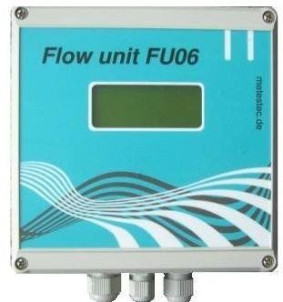
Verbrauchsmesser Typ FU06-SF-586b
        für Druckluft und Gase
                       Für Nennweiten DN15 bis DN3000

Kalorimetrischer, nach dem Wärmeabtragungsprinzip arbeitender Durchflussmesser

Merkmale
     Keine bewegten Teile
     Hohe Empfindlichkeit bei geringen Strömungsgeschwindigkeiten
     Großer Messbereich ermöglicht sowohl die Erfassung von Leckagen als auch
     von größeren Verbräuchen
     Messung des Normdurchflusses, unabhängig von Druck- und
     Temperaturschwankungen
     Parallele Messung der Medientemperatur
     Hohe Messgenauigkeit
     Vielfältige Signalausgabe in der Standardausführung (Anzeige, Schaltpunkt,
     Analogausgang, Pulsausgang, RS232-Schnittstelle)
     Lage unabhängig arbeitendes Gerät
     Einbau und Wartung einfach und problemlos

Einsatz
      Erfassung von Druckluftkosten für einzelne Kostenstellen oder Verbraucher
      Ermittlung von Leckagemengen
      Steuerung leistungsunterschiedlicher Kompressoren
      Überwachung des Leistungsgrades von Drucklufterzeugern
      Messung des Luftverbrauchs an Belebungsbecken in Kläranlagen
      Zuluftmessung an Gebäudebelüftungsanlagen
      Stickstoff-Verbrauchsmessungen

FU06SF586b-TBd       27-07-2010 Technische Änderungen vorbehalten     Seite 1 von 10
Systemübersicht

     Analog
     I/U Ausgang
                                        Messumformer
                                       Typ FU06-SF-586b
     Relais
     Wechselkontakt
                                                                        Sonde

     Tastatur
     Schnittstelle

     RS232
     Schnittstelle

     LC-Anzeige
     beleuchtet

                                                                       Standard *1
                                                                       im Gehäuse 150x150x57mm
    12 Volt DC                                                         mit 1x Pg7 und 2x Pg9
                                  *1      *2

                                          12 Volt DC                   Option *2
     24 Volt DC                                                        im Gehäuse 200x150x79mm
     oder                                                              mit 5x Pg9
     230 Volt AC

     3 x Analog Eing.
     0-5 Volt
     z.B. Druck

     Temp. Analog
      I/ U Ausgang

     M-Bus
     Schnittstelle

FU06SF586b-TBd          27-07-2010 Technische Änderungen vorbehalten            Seite 2 von 10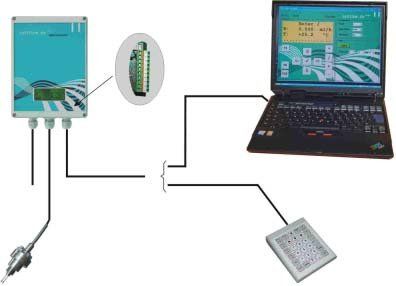
Aufbau
Der Druckluft- und Gasverbrauchsmesser besteht aus einer Sonde mit Klemmver-
schraubung G½ und einer separaten rechnergestützten Elektronik in einem
Kunststoffgehäuse zur Wandbefestigung. Die Sonde wird über eine Anschweißmuffe mit
G½ Innengewinde in die Rohrleitung Montiert.
Für den Einbau in die Rohrleitung stehen folgende Optionen zur Verfügung:
• Klemmverschraubung ohne Kugelhahn, wenn die Sonde in verschiedenen
   Rohrnennweiten in die drucklose Rohrleitung montiert werden soll.
• Klemmverschraubung mit Kugelhahn und Sicherheitsmontageeinheit,
   wenn die Sonde in verschiedenen Rohrnennweiten in die unter Druck
   stehende Rohrleitung montiert werden soll.

Ausführung
Gerät mit Durchflussanzeige (Volumenstrom, Massenstrom), Mengenzähler und
durchflussproportionalem Ausgangssignal 0–10V oder 0/4-20mA, Pulsausgang
(< 30x pro Minute) oder 1 Schaltschwelle und bidirektionaler RS232–Schnittstelle.
Bei Lieferung werksseitig nach Kundenvorgaben eingestellt: Anzeige Volumen und
Volumenstrom oder Masse und Massenstrom, Ausgangssignal Endwert,
Pulswertigkeit, Schaltschwelle/Hysterese, Baudrate, Adresse, Mittelwertbildung,
Off-Set, und Minimalmengenunterdrückung.
Bei Lieferung mit Tastatur kann der Kunde die vorgenannten Einstellungen Menü
geführt selbst vornehmen, sowie die Zähler starten, stoppen und zurücksetzen.
Der Analogausgang, die Schaltschwelle oder der Pulsausgang können den
Messwerten frei zugeordnet werden.
Über die RS232-Schnittstelle können alle genannten Einstellungen und Datenabfragen
mit einem PC durchgeführt werden.
Die erforderliche Software ist im Lieferumfang enthalten, ebenso ein 1,5m langes
Schnittstellenkabel für den Anschluss an den PC.

Anschlussschema
                                          Federkontaktklemme

                                                                RS232
                 230V, 50/60Hz

                                        RS232
                                                                RS232

FU06SF586b-TBd                   27-07-2010 Technische Änderungen vorbehalten   Seite 3 von 10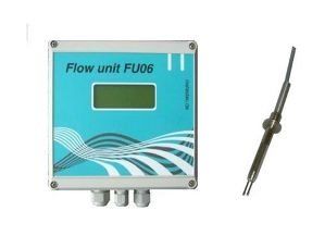
Technische Daten der Sonde

Funktionsprinzip                      kalorimetrisch, Primärsignal massenstromproportional
                                      (Betauung der Sonde muss vermieden werden)
Medium                                Luft, trocken
Messbereiche                          0,6-60m/s (bei Normbedingungen 0° C/1,013bar a)
Messfehler                            < +/-2% vom Messwert ab > 5m/s, sonst < +/- 0,1m/s
Wiederholgenauigkeit                  +/-1% vom Messwert
Bereitschaftszeit                     ca. 5 Minuten nach dem Einschalten
Betriebsdruck                         max. 16bar absolut (höhere Drücke auf Anfrage)
Betriebstemperatur                    -40°C bis +100°C
                                        0°C bis +200°C
                                        0°C bis +300°C
                                        0°C bis +400°C
                                        0°C bis +420°C (bei Bestellung festzulegen)
Umgebungstemperatur0°                   C bis +60°C
Betriebslage                          beliebig
Beruhigungsstrecke                    30 x DN im Einlauf, 10 x DN im Auslauf
                                      Die Mindestlänge der Beruhigungsstrecken hängt vom jeweiligen
                                      Anwendungsfall ab. Grundsätzlich gilt, dass größere
                                      Beruhigungsstrecken erforderlich sind, wenn Krümmer oder
                                      Armaturen im Zulauf eingebaut sind. Siehe auch DIN1952
Prozessanschluss                      Anschweißmuffe mit G½ Innengewinde
Auslegungsdruck                       PN16 (höhere auf Anfrage)
Werkstoffe, medienberührt             Sonde, Anschweißmuffe, Klemmverschraubung,
                                      Kugelhahn (optional): Edelstahl 1.4571
                                      Dichtung: VITON
Schutzart                             IP65
Abmessungen                           siehe Maßbilder der Sonden
Verbindungskabel Sonde -              Länge 5m (optional 10m)
Messumformer

Messbereichsgrenzen (bezogen auf Luft im Normzustand 0°C/1,013 bar a) bei Rohrinnendurchmesser

 15-25       32      40         50       65       80       100      200     300          3000         mm
  100        170     260        410      700     1.000    1.700    6.800   15.200     1.500.000      Nm³/h

FU06SF586b-TBd             27-07-2010 Technische Änderungen vorbehalten             Seite 4 von 10
Maßbilder der Sonden (Standard 120mm / 250mm)
Anschlusskabel
Zy linderschraube DIN912-M6
Zy linderschraube DIN912-M4
Heizer
FU06SF586b-TBd 27-07-2010 Technische Änderungen vorbehalten Seite 5 von 10Technische Daten des Messumformers
Versorgungsspannung Standard: 12VDC ohne Potentialtrennung
Option: 115-230VAC, 24VDC, 12VDC mit Potentialtrennung
Leistungsaufnahme ca. 8VAC
Umgebungstemperatur +5° C bis +50°C
Abmessungen siehe Maßbilder der Messumformer
Schutzart IP65
Anzeige LCD-Punktmatrix-Anzeige, 4 Zeilen a 16 Zeichen
Anzeigewerte Massendurchfluss und Masse (Zählung)
Volumendurchfluss und Volumen (Zählung)
Temperatur [° C]
Datensicherung durch nvSRAM (nicht-flüchtiger Speicher)
Ausgangssignale 0–10VDC oder 0/4 – 20mA* durchflussproportional
Relaisausgang (potentialfreier Wechsler)
frei programmierbar als Pulsausgang oder Schaltschwelle**
RS232, bidirektional ***
Federkontaktklemmen für alle Ein- und Ausgangssignale
Anschlussart
(max.1,0mm²)
Optionales Zubehör Tastatur, numerisch, 25 Tasten, in separatem Gehäuse mit
Anschlusskabel
* 0-20mA oder 4-20mA frei wählbar über RS232 oder Tastatur.
Spannungs- oder Stromsignal mittels Jumper frei wählbar. Konfiguration bei Lieferung 0–10V.
** Relaisausgang frei konfigurierbar über RS232 oder Tastatur.
Als Pulsausgang max. 30 Pulse/Minute für den Messbereichsendwert.
*** Interne Klemme für PC-Anschluss und interne Steckverbindung für optionale Tastatur.
Maßbilder der Messumformer
Standard Option
FU06SF586b-TBd 27-07-2010 Technische Änderungen vorbehalten Seite 6 von 10Typenschlüssel / Bestellspezifikation FU06-SF-586b
In den Positionen 1 bis 4, 6 und 7 ist jeweils zwingend eine Option auszuwählen.
Pos Beschreibung der Optionen Bestelltext xxxxxxxx
1 Typ FU06-SF-586b mit Sonde 120mm oder 250mm586a
aus Edelstahl mit 5m Verbindungskabel, mit
Edelstahl-Klemmverschraubung, mit
Terminalsoftware und RS232-Anschlusskabel.
2 Mit Kugelhahn, Montage in G½ Innengewinde K
3 Zur Montage in Rohrnennweiten bis DN300 DN300 / SL
(Sondenlänge SL=120mm oder 250mm)
Zur Montage in Rohrnennweiten bis DN3000 DN3000 / SL
(Sondenlänge SL=500mm oder 800mm)
Zur Montage in Rohrnennweiten bis DN3000 DN3000 / SL
(Sondenlänge SL=1000mm)
4 Ausgang 4–20mA 4–20mA
Ausgang 0–20mA 0–20mA
Ausgang 0–10V 0-10V
5 Sonde mit 10m Kabel L1
Andere Längen (6-25m) Lx
6 Betriebstemperatur –40°C bis +100°C 100°C
Betriebstemperatur0° C bis +200°C 200°C
Betriebstemperatur0° C bis +300°C 300°C
Betriebstemperatur0° C bis +400°C 400°C
Betriebstemperatur0° C bis +420°C 420°C
7 Spannungsversorgung 12VDC +/-2%* 12VDC-OPT
Spannungsversorgung 24VDC (18 – 36VDC)** 24VDC
Spannungsversorgung 12VDC (9 – 18VDC)** 12VDC
Spannungsversorgung 115–230V 50/60Hz** 230VAC
Stecker-Netzteil 230VAC / 12VDC NT-230VAC
8 HALAR-Beschichtung der Sonde und spezial HC
Sicherheitsmontageeinheit
9 Spezial Sicherheitsmontageeinheit mit SMU
Kugelhahn
10 Drucksensor** PS
11 Sensorschutz SHP
12 Impulsausgang mit Optokoppler** OPK
13 RS232-Ausgang im Gehäuse** RSH
14 Temperaturausgang 0/4-20mA** TC
15 Tastatur MT
16 M-Bus MB
* ohne Potentialtrennung im Gehäuse 150 x 150 x 57mm
** mit Potentialtrennung im Gehäuse 200 x 150 x 79mm
FU06SF586b-TBd 27-07-2010 Technische Änderungen vorbehalten Seite 7 von 10Einsatz und Anwendungen Luft Durchflussmessung Belüftungsdurchflüsse: Abwasseraufbereitung Verbrennungsluft: Messungen in Boilern, Öfen, Heizungen Luftstromtests: Herstellung von Pumpen, Filtern und Ausrüstungen Sprühtrocknung: Nahrungsmittel, Biopharmazie, Chemie Bodensanierung: Landwirtschaft, Deponien und Umwelt Wärmebehandlung: Verarbeitung von Metallen Trocknungsluftstrom: Herstellung von Zellstoffen und Papier Luftstrom-Wiedererwärmung: Energieerzeugung Leckage Messung: in allen Industriebereichen Abluftmessung: Halbleiterfertigung Druckluft Durchflussmessung Automatisierungs- und Prozesssysteme: in allen Industriebereichen Druckluftwerkzeuge, Lackieren: in allen Industriebereichen Transportsysteme: in allen Industriebereichen Befüllen: Verpackungsindustrie PET-, PE-Flaschen: Kunststoffbehälterherstellung Labor: Pharmaindustrie Bohren, Pipelines: Öl- und Erdgasindustrie Druckgasleitungen: Erdgas Lebensmittel- und Medikamentenherstellung und Verarbeitung: Lebensmittel- und Pharmaindustrie Stickstoff Durchflussmessung Schutzgas in Behältern: Biopharmazie, Halbleiterfertigung, Chemische Industrie Gasreinigung: Erdgas, Raffinerieindustrie Druckübertragung: Lagerbehälter, in allen Industriebereiche Kühlen, Gefrieren: Raffinerien, Lebensmittelverarbeitung Formensteuerung: Metallgießereien Wärmebehandlung: Schutzgas für Stahl und Eisen, Metallindustrie Tablettenbeschichtung: Pharma- und Ernährungsindustrie Inertisieren von Flüssiggas: Tanker, Transportbehälter Bohren, Verarbeiten: Öl- und Erdgasindustrie FU06SF586b-TBd 27-07-2010 Technische Änderungen vorbehalten Seite 8 von 10
Sauerstoff Durchflussmessung
   Hochofenverbrennung: Stahlherstellung, Gefahrengutindustrie
   Metallverarbeitung: Verarbeitung von Stahl und Nichteisenmetallen
   Glashütten: Glasherstellung und Verarbeitung
   Rohstoffe zur Oxidierung: Chemische Industrie
   Kohlevergasung: Produktion von Chemikalienrohstoffen
   Katalysatorenregeneration: Ölraffinerien
   Brennstoff-Sauerstoff-Brenner: Glasherstellung, Zellstoff und Papier
   Zellstoff-Bleichmittel: Zellstoff und Papier
   Biologische Aufbereitung: Abwasseraufbereitung

Kohlendioxid Durchflussmessung
   Schutzgasschweißen: Metallindustrie
   Härten von Gussformen: Metallindustrie
   Trockeneisproduktion: Fertigung, Bauindustrie
   Harnstoff-, Methanolproduktion: Chemische Industrie
   Ansaugen von Ölförderquellen: Erdölindustrie
   Gratbeseitigung: Gummi- und Kunststoffindustrie
   Trockeneis und CO2-Kühlmittel: Lebensmittel- und Getränkeindustrie
   Schutzgas: Lebensmittel- und Pharmaindustrie
   Düngemittelverarbeitung: Herstellung von Agrochemikalien

Abluft, Abgas und Verbrennungsgas Durchflussmessung
   Entlüftungsleitungen: in allen Industriebereichen
   Abgas-CO2: Petrochemie, Chemikalienproduktion
   SO2-Abgas: Metalle, Chemikalien, Pharmazeutika
   Fackelrohre, Fackelköpfe: Ölplattformen und Raffinerien, Chemische Industrie
   Rauchgas: Energieerzeugung
   Gas aus der Umwandlung von Abfall in Energie: Abfallaufbereitungsanlagen
   Deponien, Biogasanlagen
   Mischen von Abfallströmen: Verbrennungsöfen, in allen Industriebereichen
   Rückgewinnung von Fackelgas: Erzeugung von Elektrizität, Dampf, Heißwasser
   Entsorgung von nicht brennbarem Gas: Zellstoff- und Papierindustrie

FU06SF586b-TBd       27-07-2010 Technische Änderungen vorbehalten         Seite 9 von 10
Kontakt
metes technology GmbH
Hohle Trift 4-6
D-99706 Bendeleben
Phone: +49(0)34671/5579-0
Fax: +49(0)34671 55793-11
E-Mail:info@metestec.de
www.metestec.de

FU06SF586b-TBd     27-07-2010 Technische Änderungen vorbehalten   Seite 10 von 10
17.07.2009

Consumption meter type FU06-SF-586b
    for compressed air and gases
                             for nominal width DN15 to DN3000

Calorimetric flow meter, utilising     the heat dissipation principle

Features
      No moving parts
      High sensitiveness in low flow ranges
      Wide measuring ranges allow the detection of leakage and
      increases in consumption
      Measuring of mass flow independent of pressure and temperature variations
      Parallel measurment of the temperature of the medium
      High accuracy
      Multiple signal outputs for standard model,
      (Indication, set points, analog output, pulse output, RS232-interface)
      Operates in any position
      Easy installation and maintenance

Applications
      Record of compressed air consumption by department or individual equipment
      Determine of losses from leakage
      Optimise control of multiple air compressors to increase efficiency
      Control of compressor’s efficiency factor
      Air input control in vitalizing basins of waste water treatment plants
      Ventilation control in buildings
      Nitrogen consumtion measuring

FU06SF586b-TBe             20/07/2010 Subject to technical changes      Page 1 of 10
System overview
Analog Converter electronic
I/U output type FU06-SF-586b
Relay
S.P.C.O. contact
Probe
Keyboard
Interface
RS232
Interface
LC-indication
illuminated
Standard *1
in housing 150x150x57mm
12 Volt DC with 1x Pg7 and 2x Pg9
*1 *2
12 Volt DC Option *2
24 Volt DC in housing 200x150x79mm
or with 5x Pg9
230 Volt AC
3 x analog input
0-5 Volt
e.G. pressure
Temp. Analog
I/ U output
M-Bus
I/O port
FU06SF586b-TBe 20/07/2010 Subject to technical changes Page 2 of 10Performance
The compressed air and gas consumption meter consists of a probe with clamp coupling
and a separate computer assisted converter electronics contained in a plastics
housing for simple wall mounting.
The probe is mounted into the pipe via a connecting socked with G½ female thread.
For the installation the following options are available:
• clamp coupling without ball valve , suitable for installing in different pipe sizes,
mounting while pipe is pressure less.
• clamp coupling with ball valve and safety mounting unit , suitable for installing
in different pipe sizes, mounting while pipe is under pressure.
Options
Unit with indication of actual flow rate (standard volume flow, mass flow), totalizer and
output signal 0-10V, or 0/4-20mA proportional to flow, bidirectional interface RS232,
pulse output (< 30x per minute) or set point.
Manufacturer sets the following as the customer requested:
Inner diameter of pipe, sensor surface, standard density, indication of actual flow rate in
terms of standard volume or mass volume, totalized flow in terms of standard volume or
mass volume, output signal (max. value), pulses, set point, baud rate, address,
mean value creation, off-set, min. quantity suppression.
If a keyboard is supplied the customer can set the above values as well as starting,
stopping and resetting the totalizer. Analog and pulse output as well as set point can be
coordinated to each measured value via keyboard.
All measured values and configuration can be transferred by a PC using
the RS232-interface.
The software for the PC and a cable with length of 1,5m is part of delivery.
Electrical connection
Cage clamp
RS232
RS232
230V, 50/60Hz
RS232
FU06SF586b-TBe 20/07/2010 Subject to technical changes Page 3 of 10Technical data of the probe
Operating Principle heat dissipation principle, primary signal proportional to
mass flow (moisture must be avoided)
Medium compressed air, dry (normal density 0°C/1,013bar a)
Measuring Range 0.6-60m/s (with reference to normal conditions)
Accuracy < +/-2% of measured value from > 5m/s,
< +/-0,1m/s if below 5m/s
Repeatability +/-1% from the measured value
Warming up time about 5 minutes after switching on
Operating pressure max. 16bar absolute, higher values on request
Operating temperature -40° C to +100°C
0°C to +200°C
0°C to +300°C
0°C to +400°C
0°C to +420°C (to be specified with order)
Surrounding temperature 0°C to +60°C
Installation position any
Steadying distance 30 x nom. pipe bore upstream, 10 x nom. pipe bore downstream.
The minimum steadying distance depends upon the application.
Longer steadying distances have to be considered,
if double elbows or partly closed valves have been installed in
front of the unit. See also DIN 1952.
Process connection welding socket with G½ female thread
Pressure range PN16, higher values on request
Wetted parts probe; welding socket, clamp coupling,
ball valve (optional): stainless steel 1.4571
O-ring: VITON
Protection class IP65
Housing dimension see drawings of probe dimensions
Connecting cable probe- length 5m (optional 10m)
converter
Measuring range limits (referred to air under normal conditions 0°C/1,013bar a) with inner diameter
15-25 32 40 50 65 80 100 200 300 3000 mm
100 170 260 410 700 1.000 1.700 6.800 15.200 1.500.000 Nm³/h
FU06SF586b-TBe 20/07/2010 Subject to technical changes Page 4 of 10Probe dimensions (standard 120mm / 250mm)
Anschlusskabel
Connecting cable
Heater
FU06SF586b-TBe 20/07/2010 Subject to technical changes Page 5 of 10Technical data of the converter
Power supply 12VDC +/- 2% not isolated
optional: 115-230VAC, 18–36VDC, 9-18VDC isolated
Consumption ca. 8VAC
Surrounding temperature +5° C to +50°C
Housing dimensions see drawings of housing dimensions
Weatherproof to DIN 40 050 IP65
Indication LCD-point-matrix display, 4 lines each 16 figures
Indication values mass flow, consumption (totalizer)
volume flow, consumption (totalizer),
temperature [° C]
Data storage by nvSRAM
Output signals 0–10VDC or 0/4–20mA proportional to flow*
relay output (S.P.C.O. contact)
free programmable as pulse output or set point**
RS232, bidirectional ***
Electrical connections spring-cage connection for all input and output signals
(max.1,0mm²)
Optional Accessories keyboard, numeric, 25 keys, in separate housing with
connecting cable
* voltage- or current signal via jumper free programmable; configuration at delivery 0–10V;
0-20mA or 4-20mA free programmable via RS232.
** relay output free programmable via RS232;
pulse output max. 30 pulses/minute for full scale value.
*** internal terminal for PC-connection and internal connection for option keyboard.
Housing dimensions
standard option
FU06SF586b-TBe 20/07/2010 Subject to technical changes Page 6 of 10Type key / specification for ordering FU06-SF-586b
For positions 1 to 4, 6 and 7 one option must be chosen.
Pos Beschreibung der Optionen Bestelltext xxxxxxxx
1 Typ FU06-SF-586b mit Sonde 120mm oder 250mm 586a
aus Edelstahl mit 5m Verbindungskabel, mit
Edelstahl-Klemmverschraubung, mit
Terminalsoftware und RS232-Anschlusskabel.
2 Mit Kugelhahn, Montage in G½ Innengewinde K
3 Zur Montage in Rohrnennweiten bis DN300 DN300 / SL
(Sondenlänge SL=120mm oder 250mm)
Zur Montage in Rohrnennweiten bis DN3000 DN3000 / SL
(Sondenlänge SL=500mm oder 800mm)
Zur Montage in Rohrnennweiten bis DN3000 DN3000 / SL
(Sondenlänge SL=1000mm)
4 Ausgang 4–20mA 4–20mA
Ausgang 0–20mA 0–20mA
Ausgang 0–10V 0-10V
5 Sonde mit 10m Kabel L1
Andere Längen (6-25m) Lx
6 Betriebstemperatur –40°C bis +100°C 100°C
Betriebstemperatur0° C bis +200°C 200°C
Betriebstemperatur0° C bis +300°C 300°C
Betriebstemperatur0° C bis +400°C 400°C
Betriebstemperatur0° C bis +420°C 420°C
7 Spannungsversorgung 12VDC +/-2%* 12VDC-OPT
Spannungsversorgung 24VDC (18 – 36VDC)** 24VDC
Spannungsversorgung 12VDC (9 – 18VDC)** 12VDC
Spannungsversorgung 115–230V 50/60Hz** 230VAC
Stecker-Netzteil 230VAC / 12VDC NT-230VAC
8 HALAR-Beschichtung der Sonde und spezial HC
Sicherheitsmontageeinheit
9 Spezial Sicherheitsmontageeinheit mit SMU
Kugelhahn
10 Drucksensor** PS
11 Sensorschutz SHP
12 Impulsausgang mit Optokoppler** OPK
13 RS232-Ausgang im Gehäuse** RSH
14 Temperaturausgang 0/4-20mA** TC
15 Tastatur MT
16 M-Bus MB
* not isolated, with housing 150 x 150 x 57mm
** isolated, with housing 200 x 150 x 79mm
FU06SF586b-TBe 20/07/2010 Subject to technical changes Page 7 of 10Applications and industry Air Flow Measurment aeration flows: wastwater treatment combustion air: measuring in boilers, kilns,heaters air flow test: manufacturer of pumps, filters and equipment spray drying: food, bio-pharm, chemical soil remediation: agriculture, landfill und environmental heat treating: processing of metals drying air flow: manufacturing of cellulose and paper reheat air flow: power generation leakage measurment: in all industries exhaust air measurement: manufacturing of semiconductors Compressed Air Flow Measurment automation and prozess systems: in all industries pneumatic tools, paiting: in all industries transport and handling systems: in all industries filling: packing industry PET-, PE-bottle: manufacturer of plastic container laboratory: pharmaceutical industry drilling, pipelines: oil and natural gas industry pressurizing gas lines: natural gas food and drug manufacturing and processing: food und pharmaceutical industry Nitrogen Gas Flow Measurment tank blanketing: bio-pharm, semiconductors, chemical industry gas purging: natural gas, refinery industry pressure transfer: storage vessels, in all industries cooling, freezing: refineries, food processing forming control: metal casting heat treatment: shield gas for steel and iron, metal industry tablet coating: pharmaceutical and food industry Inerting of liquid natural gas: tankers, transport vessels Drilling, processing: oil and natural gas industry FU06SF586b-TBe 20/07/2010 Subject to technical changes Page 8 of 10
Oxygen Gas Flow Measurment
   furnace combustion: Steel making, hazard material industry
   metal processing: steel and non-ferrous metal processing
   glas smelters: glas manufacturing and processing
   raw material for oxidation: chemical industry
   coal gasification: chemical feedstock production
   catalyst regeneration: oil refineries
   oxy-fuel furnaces: glas manufacturing, cellulose and paper
   bleaching agent: cellulose and paper
   biological treatment: wastewater treatment

Carbon Dioxide Flow Measurment
   gas-shielded welding: metal industry
   casting mold hardening: metal industry
   dry-ice feed: manufacturing, building industry
   urea, methanol production: chemical industry
   oil extraction well priming: petroleum industry
   flash removal: rubber and plastic industry
   dry ice and CO2-coolant: food and beverage industry
   inert gas: food and pharmaceutical industry
   fertilizer processing: manufacturing of agricultural chemicals

Exhaust and Waste Gas Flow Measurment
   vent lines: in all industries
   waste CO2: petrochemicals, chemical production
   SO2 off gas: metals, chemicals, pharmaceuticals
   flare stacks, headers: oil platforms and refineries, chemical industry
   flue gas: power generation
   waste-to-energy gas: waste treatment systems, landfill, biogas plant
   waste flow mixing: incinerators, in all industries
   flare gas recovery: generation of electricity, steam, hot water
   gas disposal: cellulose and paper industry

FU06SF586b-TBe            20/07/2010 Subject to technical changes           Page 9 of 10
Contact
metes technology GmbH
Hohle Trift 4-6
D-99706 Bendeleben
Phone:+49(0)34671/55793-0
Fax: +49(0)34671/55793-11
E-Mail: info@metestec.de
www.metestec.de

FU06SF586b-TBe        20/07/2010 Subject to technical changes   Page 10 of 10
Sie können auch lesen