ZU1099 - Knick International
←
→
Transkription von Seiteninhalten
Wenn Ihr Browser die Seite nicht korrekt rendert, bitte, lesen Sie den Inhalt der Seite unten
ZU1099
       User Manual                 Sensor Securing System for
                                   ARI106/106H Inline Fitting

English....................... 3
Deutsch..................... 11

Read before installation.
Keep for future use.                                      www.knick.de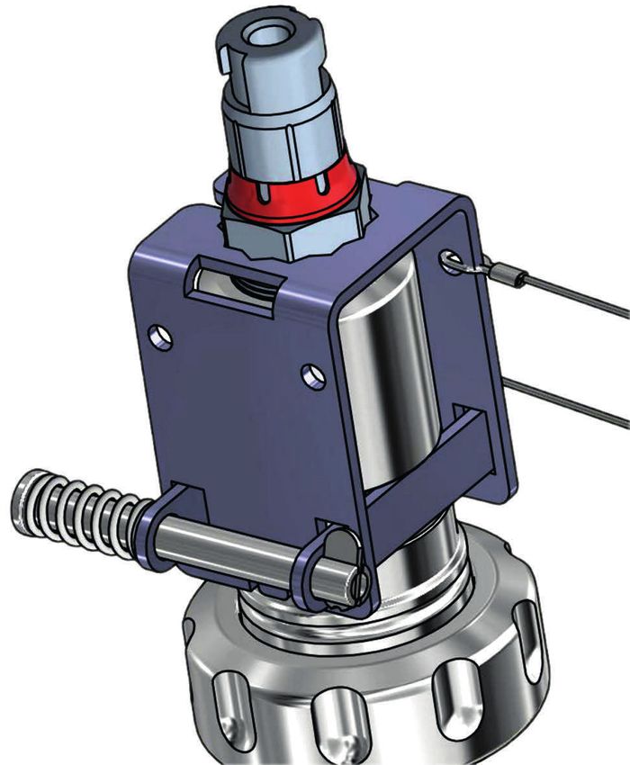
Table of Contents
English....................................................................................................................    3
Deutsch..................................................................................................................     11
ZU1099
      User Manual             Sensor Securing System for
                              ARI106/106H Inline Fitting

Read before installation.
Keep for future use.
Copyright 2021 • Subject to change
Version: 3 • Published on June 07, 2021              www.knick.de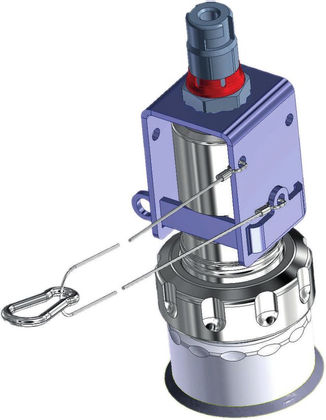
ZU1099

Supplemental Directives
READ AND SAVE THIS DOCUMENT FOR FUTURE REFERENCE. BEFORE
ATTEMPTING TO ASSEMBLE, INSTALL, OPERATE OR MAINTAIN THE
PRODUCT, PLEASE ENSURE A COMPLETE UNDERSTANDING OF THE
INSTRUCTIONS AND RISKS DESCRIBED HEREIN. ALWAYS OBSERVE
ALL SAFETY INFORMATION. FAILURE TO COMPLY WITH INSTRUC-
TIONS IN THIS DOCUMENT COULD RESULT IN SERIOUS INJURY AND/
OR PROPERTY DAMAGE. THIS DOCUMENT IS SUBJECT TO CHANGE
WITHOUT NOTICE.
These supplemental directives explain how safety information is
laid out in this document and what content it covers.
Safety Chapter
This document's safety chapter is designed to give the reader a ba-
sic understanding of safety. It illustrates general hazards and gives
strategies on how to avoid them.
Symbols Used in this Document
Symbol Meaning
         Interim or final result in instructions for action

         Sequence of figures attached to an instruction for action

         Item number in a figure

         Item number in text

Related Documents
• ARI106 / ARI106H inline fitting user manual. See www.knick.de
• Sensor manufacturer user manual.

                                         4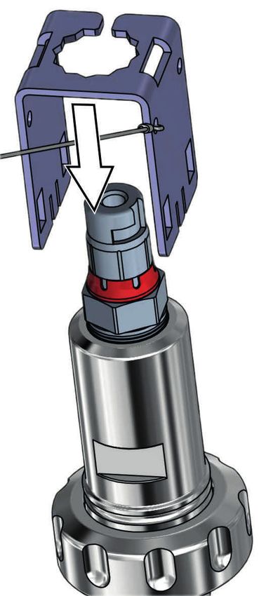
ZU1099

1 Safety
This document contains important instructions for the use of the
product. Always follow all instructions and operate the product
with caution. If you have any questions, please contact Knick
Elektronische Messgeräte GmbH & Co. KG (sometimes hereafter
referred to as "Knick") using the information provided on the back
page of this document.
Intended Use
Accessory ZU1099 prevents the screw joint between the
ARI106/106H inline fitting and a sensor from accidentally coming
loose. There is a risk of process medium escaping if the screw joint
is loose.
Possible causes:
• Vibration or pressure blows in the process
• Sensors not tightened as specified
The accessory is approved for use with:
• sensors with a diameter of 12 mm , A/F 19, and a PG 13.5 process
  connection.
• ARI106/106H inline fittings with A/F 24 1).
The product has been developed and manufactured in accordance
with generally accepted safety rules and regulations.
Note: The latest user manuals for fittings and sensors can be found
at www.knick.de.
Personnel Requirements
Customer shall ensure that any personnel using or otherwise inter-
acting with the product is adequately trained and has been prop-
erly instructed.

1)   A/F 24 at the fitting head.
                                   5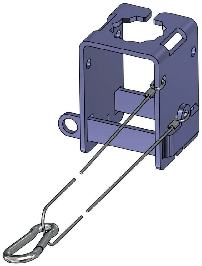
ZU1099
The operating company shall comply and cause its personnel to
comply with all applicable laws, regulations, codes, ordinances and
relevant industry qualification standards related to product. Failure
to comply with the foregoing shall constitute a violation of operat-
ing company’s obligations concerning the product, including but
not limited to an unintended use as described in this document.

                                  6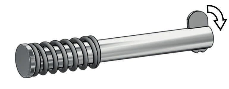
ZU1099
2 Product
2.1 Package Contents
• ZU1099
• User Manual
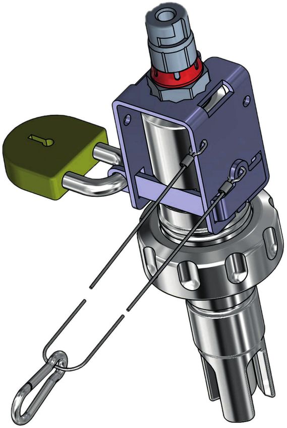
Design and Function
The ZU1099 sensor securing system ensures a secure connection
between the sensor and the inline fitting. The sensor securing
system can be secured in the system using the snap hook. It thus
always remains near the measuring point when sensors are
installed or removed.
Design
1
2
4
3
1 Bracket 3 Stainless steel cable with snap hook
2 Retainer 4 Drop nose pin with spring
7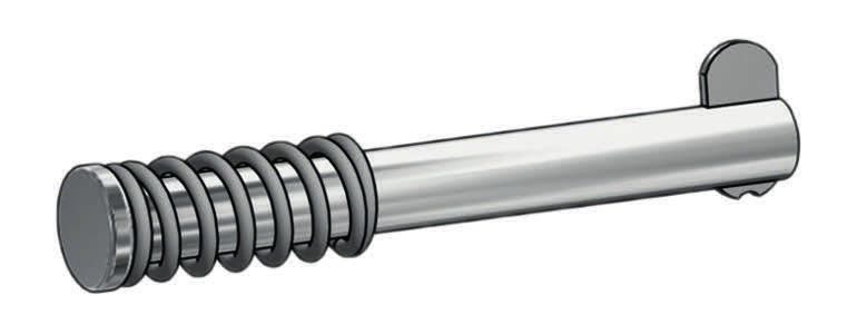
ZU1099
Installation

                                1

                                2
                                                                   5

                                3

                                4

                          A/F 24                     7             6
01. Screw the sensor (3) into the fitting (4).
02. Slide the bracket (2) over the sensor (3) and on to the
    fitting (4).
03. Align the bracket (2) with the sensor (3) and the fitting (4).
Note: Align the star-shaped cutout (1) in the bracket (2) with the
hexagon of the sensor (3). While doing so, pay attention to the re-
tainer (5), which is aligned with the A/F 24 face of the inline fitting.
04. Install the retainer (5).
05. Fold down the nose (6) on the drop nose pin (7).
                                8
ZU1099
9
5
8 6
10
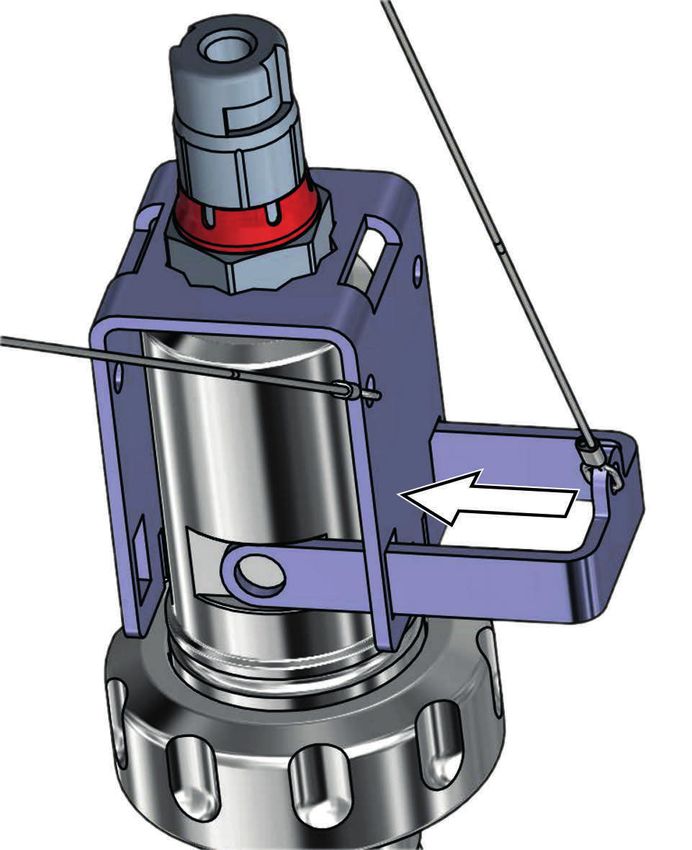
06. Slide the drop nose pin (7) through the openings (8) in the re-
tainer (5) and fold up the nose (6).
✓ The sensor is now protected from any loosening of the screw
joint.
Note: As an alternative to the drop nose pin (7), a padlock (9) 1)
may be used.
07. Fasten the sensor securing system in position at the measuring
point using the snap hook (10).
1) Not included
9ZU1099
Specifications
Material
Bracket Stainless steel A2 (1.4301) AISI 304
Retainer Stainless steel A2 (1.4301) AISI 304
Drop nose pin (Ø 6 mm) Stainless steel A2 (1.4301) AISI 304
Stainless steel cable (Ø 1 mm) Stainless steel A4 (1.4401) AISI 316
Snap hook (30 mm x 3 mm) Stainless steel A4 (1.4401) AISI 316
Compression spring Stainless steel A2 (1.4310) AISI 301
10ZU1099
Betriebsanleitung Sensorsicherung für Einbauarmatur
ARI106/106H
Vor Installation lesen.
Für künftige Verwendung aufbewahren.
Copyright 2021 • Änderungen vorbehalten
Version: 3 • Veröffentlicht am 07.06.2021 www.knick.deZU1099
Ergänzende Hinweise
Lesen Sie dieses Dokument und bewahren Sie es für künftige Ver-
wendung auf. Stellen Sie bitte vor der Montage, der Installation,
dem Betrieb oder der Instandhaltung des Produkts sicher, dass Sie
die hierin beschriebenen Anweisungen und Risiken vollumfänglich
verstehen. Befolgen Sie unbedingt alle Sicherheitshinweise. Die
Nichteinhaltung von Anweisungen in diesem Dokument kann
schwere Verletzungen von Personen und/oder Sachschäden zur
Folge haben. Dieses Dokument kann ohne Vorankündigung geän-
dert werden.
Die folgenden ergänzenden Hinweise erläutern die Inhalte und den
Aufbau von sicherheitsrelevanten Informationen in diesem Doku-
ment.
Sicherheitskapitel
Im Sicherheitskapitel dieses Dokuments wird ein grundlegendes
Sicherheitsverständnis aufgebaut. Es werden allgemeine Gefähr-
dungen aufgezeigt und Strategien zu deren Vermeidung gegeben.
Verwendete Symbole in diesem Dokument
Symbol Bedeutung
Zwischen- oder Endergebnis in einer Handlungsanweisung
Ablaufrichtung in Abbildungen einer Handlungsanweisung
Positionsnummer in einer Abbildung
Positionsnummer im Text
Mitgeltende Dokumente
• Betriebsanleitung der Einbauarmatur ARI106 bzw. ARI106H.
Siehe www.knick.de
• Betriebsanleitung des Sensorherstellers.
12ZU1099
1 Sicherheit
Dieses Dokument enthält wichtige Anweisungen für den Gebrauch
des Produkts. Befolgen Sie diese immer genau und betreiben Sie
das Produkt mit Sorgfalt. Bei allen Fragen steht die Knick
Elektronische Messgeräte GmbH & Co. KG (nachstehend auch als
„Knick“ bezeichnet) unter den auf der Rückseite dieses Dokuments
angegebenen Kontaktdaten zur Verfügung.
Bestimmungsgemäßer Gebrauch
Das Zubehör ZU1099 sichert den Sensor in der Einbauarmatur
ARI106/106H gegen unbeabsichtigtes Lösen der Schraubverbin-
dung zwischen der Einbauarmatur und dem Sensor. Durch das
Lösen der Schraubverbindung besteht die Gefahr, dass Prozess-
medium austritt.
Mögliche Ursachen:
• Vibrationen oder Druckschläge im Prozess
• Sensoren, die nicht vorschriftsmäßig fest angezogen wurden
Das Zubehör ist zugelassen für:
• Sensoren mit Durchmesser 12 mm, SW19 und Prozessadaption
PG 13,5.
• Einbauarmaturen ARI106/106H mit SW24 1).
Das Produkt ist nach den anerkannten sicherheitstechnischen
Regeln der Technik entwickelt und gefertigt.
Hinweis: Aktuelle Betriebsanleitungen der Armaturen und Sen-
soren unter www.knick.de.
Anforderung an das Personal
Der Kunde muss sicherstellen, dass Mitarbeiter, die das Produkt ver-
wenden oder anderweitig damit umgehen, ausreichend ausgebil-
det sind und ordnungsgemäß eingewiesen wurden.
1) SW24 am Kopf der Armatur.
13ZU1099
Der Betreiber muss sich an alle das Produkt betreffenden anwend-
baren Gesetze, Vorschriften, Verordnungen und relevanten Qualifi-
kationsstandards der Branche halten und dafür Sorge tragen, dass
auch seine Mitarbeiter dies tun. Die Nichteinhaltung der vorge-
nannten Bestimmungen stellt eine Pflichtverletzung durch den Be-
treiber in Bezug auf das Produkt dar. Dieser nicht bestimmungsge-
mäße Gebrauch des Produkts ist nicht zulässig.
14ZU1099
2 Produkt
2.1 Lieferumfang
• ZU1099
• Betriebsanleitung
Aufbau und Funktion
Mit der Sensorsicherung ZU1099 ist der Sensor sicher mit der
Einbauarmatur verbunden. Die Sensorsicherung kann mit dem
Karabinerhaken in der Anlage gesichert werden und bleibt somit
beim Ein- und Ausbau der Sensoren immer in der Nähe der
Messstelle.
Aufbau
1
2
4
3
1 Bügel 3 Edelstahlseil mit Karabinerhaken
2 Sicherungsbügel 4 Klappnasenbolzen mit Feder
15ZU1099
Installation
1
2
5
3
4
SW24 7 6
01. Sensor (3) in Armatur (4) schrauben
02. Bügel (2) über den Sensor (3) auf die Armatur (4) schieben.
03. Bügel (2) zum Sensor (3) und Armatur (4) ausrichten.
Hinweis: Den sternförmigen Ausschnitt (1) am Bügel (2) am Sechs-
kant des Sensors (3) ausrichten. Dabei auf den Sicherungsbügel (5)
achten. Dieser wird zur Schlüsselfläche SW24 der Einbauarmatur
ausgerichtet.
04. Sicherungsbügel (5) installieren.
05. Am Klappnasenbolzen (7) die Nase (6) herunterklappen.
16ZU1099
9
5
8 6
10
06. Klappnasenbolzen (7) durch die Öffnungen (8) des Siche-
rungsbügel (5) schieben und die Nase (6) wieder hochklappen.
✓ Der Sensor ist gegen Lösen der Verschraubung gesichert.
Hinweis: Alternativ zum Klappnasenbolzen (7) kann ein Vorhänge-
schloss (9) 1) verwendet werden.
07. Sensorsicherung mit Karabinerhaken (10) an der Messstelle
fixieren.
1) nicht Bestandteil des Lieferumfangs
17ZU1099
Technische Daten
Material
Bügel Edelstahl A2 (1.4301) AISI 304
Sicherheitsbügel Edelstahl A2 (1.4301) AISI 304
Klappnasenbolzen (Ø 6 mm) Edelstahl A2 (1.4301) AISI 304
Edelstahlseil (Ø 1 mm) Edelstahl A4 (1.4401) AISI 316
Karabinerhaken (30 mm x 3 mm) Edelstahl A4 (1.4401) AISI 316
Druckfeder Edelstahl A2 (1.4310) AISI 301
18ZU1099
Notizen
19Knick Elektronische Messgeräte GmbH & Co. KG Headquarters Beuckestraße 22 • 14163 Berlin Deutschland Tel.: +49 30 80191-0 Fax: +49 30 80191-200 info@knick.de www.knick.de Local Contacts www.knick-international.com Copyright 2021 • Subject to change Version 3 • This document was published on 6/7/2021. Aktuelle Dokumente finden Sie zum Herunterladen auf unserer Website unter dem entsprechenden Produkt. TA-ZU1099-KNXX03 098709
Sie können auch lesen