ISOMETER isoPV1685xxx-425 - Isolationsüberwachungsgerät / Insulation monitoring device - Bender UK
←
→
Transkription von Seiteninhalten
Wenn Ihr Browser die Seite nicht korrekt rendert, bitte, lesen Sie den Inhalt der Seite unten
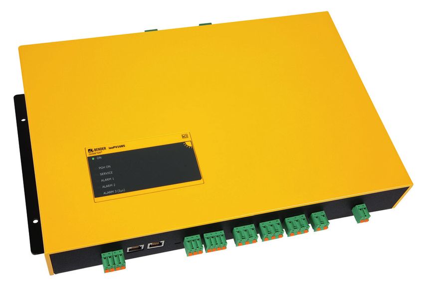
ISOMETER® isoPV1685xxx-425
Isolationsüberwachungsgerät / Insulation monitoring device

Ab Seriennummer / From serial number 2108…

isoPV1685xxx_D00007_02_Q_DEEN / 10.2021                  Quickstart DE/EN
ISOMETER® isoPV1685xxx-425

Kurzanleitung                                                     Quick-start guide
Diese Kurzanleitung gilt für folgende Geräte:                     This guide applies to the following devices:
        Gerät                 Überwachtes IT-System          Messstrom Im               Ansprechwerte        Bestellnummer
        Device              IT system being monitored     Measuring current Im          Response values       Order number
    isoPV1685RTU-425        AC 0…1000 V * / DC 0…1500 V         ≤1,5 mA                      200 Ω…1 MΩ         B91065603
      isoPV1685P-425              DC 0…1500 V                   ≤1,5 mA                      200 Ω…1 MΩ         B91065604

* Nicht in UL-Anwendungen                                         * not in UL applications

    i     Die Kurzanleitung ersetzt nicht das Handbuch.
          Das Handbuch finden Sie auf unserer Home-
                                                                     i
                                                                  This quick-start guide does not replace the ope-
                                                                  rating manual. You can find the operating ma-
          page:                                                   nual on our homepage:
                               https://www.bender.de/service-support/downloadbereich

Bestimmungsgemäße Verwendung                                      Intended use
Das ISOMETER® überwacht den Isolationswiderstand                  The ISOMETER® monitors the insulation resistance of
von ungeerdeten DC-Stromkreisen bis DC 1500 V in                  unearthed DC circuits up to DC 1500 V in photovoltaic
Photovoltaikanlagen.                                              systems.
Die separate Versorgungsspannung ermöglicht die                   A separate supply voltage allows de-energised
Überwachung eines spannungslosen Systems.                         systems to be monitored.
Zum bestimmungsgemäßen Betrieb ist die Spezifika-                 For proper operation, the specification in the techni-
tion in den Technischen Daten zu beachten. Eine an-               cal data must be observed. Any other use or use that
dere oder darüber hinausgehende Benutzung gilt als                goes beyond this is considered improper use.
nicht bestimmungsgemäß.
Sicherheitshinweise                                               Safety instructions

I                                                                 I
          Gefahr eines elektrischen Schlages!                                Danger! Risk of electric shock!
          An den Klemmen liegt eine hohe Spannung an,                        The terminals carry high voltage and direct
          die bei direkter Berührung lebensgefährlich ist.                   contact with these terminals will likely result in
          Ist das Gerät mit den Klemmen L1/+, L2– an ein                     electrocution. If the terminals L1/+, L2– of the
          spannungsführendes IT-System angschlossen,                         device are connected to a live IT system, the
          dürfen die Klemmen KE und E nicht vom Schutz-                      terminals E and KE must not be disconnected
          leiter (PE) getrennt werden                                        from the protective conductor (PE).

I                                                                 I
          Vorsicht Sachschaden durch unsachgemäße                            Caution! of damage to property due to incor-
          Installation!                                                      rect installation!
          Die Anlage kann Schaden nehmen, wenn Sie                           Connecting more than one insulation monito-
          mehr als ein Isolationsüberwachungsgerät an-                       ring device may result in damage to the instal-
          schließen. Sind mehrere Geräte angeschlossen,                      lation. If more than one insulation monitoring
          funktioniert das Gerät nicht und meldet keine                      device is connected, the device will not function
          Isolationsfehler.                                                  and will report no insulation fault.

I                                                                 I
          Vorsicht Trennung vom IT-System!                                   Caution Disconnect from the IT system!
          Bei Isolations- und Spannungsprüfungen an                          The insulation monitoring device must be dis-
          der Anlage muss das Isolationsüberwachungs-                        connected from the IT system before insulation
          gerät für die Dauer der Prüfung vom IT-System                      or voltage tests are carried out at the installa-
          getrennt sein. Andernfalls kann das Gerät                          tion. Otherwise the device may be damaged

                                                                     i
          Schaden nehmen.
                                                                             When the IT system to be monitored contains
    i     Wenn ein überwachtes IT-System galvanisch
          gekoppelte Gleichstromkreise enthält, kann ein
                                                                             galvanically coupled DC circuits, take into con-
                                                                             sideration that: an insulation fault can only be
          Isolationsfehler nur dann richtig erfasst wer-                     detected correctly when the rectifier valves car-
          den, wenn über die Gleichrichterventile ein                        ry a minimum correctly when the rectifier valves
          Mindeststrom von > 10mA fließt.                                    carry a minimum current of > 10 A

2       isoPV1685xxx_D00007_02_Q_DEEN / 10.2021
ISOMETER® isoPV1685xxx-425
Montage Mounting
Richten Sie das Gerät so aus, dass es im Betrieb senk- Align the device in such a way that it is vertically
recht steht und die Netzankopplung (L1/+, L2/–) oben upright during operation and that the system cou-
ist. pling (L1/+, L2/–) is on top.
> 20
5,2
8,75
M5
246
125
61,8
iso1685
ISOMETER®
64
76,6
106
40,5
Nm
39,8
> 20
40,75
55,7
51
368
383
401,5
Maße in mm / dimensions in mm
Anschluss Connection
Verdrahten Sie das Gerät gemäß Anschlussbild. Wire up the device according to the wiring diagram
Beachten Sie dabei die technischen Daten. taking account of the technical data.
I I
Gefahr eines elektrischen Schlages! Danger! Risk of electric shock!
Bei Berühren von spannungsführenden nicht Touching uninsulated live conductors can re-
isolierten Leitern können Tod oder schwere sult in death or serious injury. Therefore avoid
Körperverletzung eintreten. Vermeiden Sie des- any physical contact with active conductors.
halb jeglichen Körperkontakt mit aktiven Ensure compliance with the regulations for
Leitern. Beachten Sie die Regeln für das Arbeiten working on electrical installations.
an elektrischen Anlagen.
I I
Warnung! Nicht korrekt arbeitende Isola- Warning! Insulation monitoring devices that
tionsüberwachungsgeräte! do not work correctly!
Schließen Sie die Klemmen KE und E getrennt Connect the terminals KE and E individually to
mit je einer Leitung an den Schutzleiter PE an. the protective earth conductor PE.
i Die Klemmen L1/+ und L2/– sind verriegelt.
Zum Abziehen der Klemmen müssen zunächst
i The terminals L1/+ and L2/– are locked. To de-
tach the terminals, first push the lateral orange
die seitlichen orangefarbenen Schieber nach slider forward (direction of the device) to unlock
vorne (Richtung Gerät) geschoben werden, um the terminal. Then the terminal can be deta-
die Klemmen zu entriegeln. Erst dann können ched.
die Klemmen abgezogen werden.
isoPV1685xxx_D00007_02_Q_DEEN / 10.2021 3ISOMETER® isoPV1685xxx-425
Anschlussbild Wiring diagram
nur isoPV1685 RTU (nicht in UL-Anwendungen)
only isoPV1685RTU (not in UL applications)
L1 L1 L1
L2 Un Un
L3
Un L2 L2
1A 1A 1A 1A 1A 1A
L1/+ L2/- L1/+ L2/- L1/+ L2/-
L1/+ L1/+ L2/- L2/-
1 A4
2 A3
3 A2
4 A1
SS8103 5 A0
6
7
8
ST6101
µSDCard
RS-485
I2+ I2- I1+ I1- CAN1 CAN2 Term. A B S k l kT lT 31 32 34 21 22 24 11 12 14 E KE A1 A2
US
PE 6A 6A
- A B S E KE A1 A2
+ K3 K2 K1
I2+ I2- I1+ I1- 31 32 34 21 22 24 11 12 14
4 isoPV1685xxx_D00007_02_Q_DEEN / 10.2021ISOMETER® isoPV1685xxx-425
Legende Legend
Klemme Anschlüsse Terminal Connections
I1–, I1+ Digitale Eingänge I1–, I1+ Digital inputs
I2–, I2+ I2–, I2+
CAN1, CAN2 CAN Schnittstelle CAN1, CAN2 CAN interface
RS-485 Term. DIP-Schalter zur Terminierung der RS-485 Term. DIP switch for the termination of the RS-485
RS-485-Schnittstelle interface
A, B, S Serielle Schnittstelle RS-485 A, B, S Serial RS-485 interface
k, l, kT, lT Ohne Funktion k, l, kT, lT No function
31, 32, 34 Relaisausgang für interne Gerätefehler und 31, 32, 34 Relay output for internal device errors and
Anschlussfehler connection faults
21, 22, 24 Relaisausgang für Alarm Isolationsfehler 21, 22, 24 Relay output for alarm insulation fault
11, 12, 14 Relaisausgang für Alarm Isolationsfehler 11, 12, 14 Relay output for alarm insulation fault
E, KE Separate Anschlüsse von E (Erde) E, KE Separate connections of E (earth)
und KE (Kontrollerde) an PE and KE (control earth) to PE
A1, A2 Versorgungsspannung Us DC 24 V A1, A2 Connection to Us = DC 24 V
L1/+ Ankopplung Klemme L1/+ L1/+ Coupling terminal L1/+
L2/– Ankopplung Klemme L2/– L2/– Coupling terminal L2/–
SS8103 Ohne Funktion SS8103 No function
ST6101 Rücksetzen von Alarmen ST6101 Alarm resetting
µSDCard Datenlogger nur isoPV1685P µSDCard Data logger isoPV1685P only
Anschluss Vorgehen Connection procedure
1. Klemme E und KE an Erde (PE) anschließen. 1. Connect terminals E and KE to earth (PE).
2. Klemme A und B an BMS-Bus anschließen. 2. Connect A and B to the BMS bus.
3. Klemme S an den Schirm der Bus-Leitung anschlie- 3. Connect terminal S to the shield of the bus line
ßen (nur an einem Ende der Leitung). (only at the end of the line).
4. Klemme L1/+ an L1/+ des IT-Netzes anschließen 4. Connect terminal L1/+ to L1/+ of the IT system
(mit je 1 A-Sicherung). (with one 1 A fuse each).
5. Klemme L2/– an L2/– des IT-Netzes anschließen 5. Connect terminal L2/– to L2/– of the IT system
(mit je 1 A-Sicherung). (with one 1 A fuse each).
6. Klemme A1/A2 an die Versorgungsspannung Us 6. Connect terminal A1/A2 to the supply voltage Us
anschließen (mit je 6 A-Sicherung). (with one 6 A fuse each).
7. Meldeausgänge 11/12/14, 21/22/24 und 31/32/34 7. Connect the alarm outputs 11/12/14, 21/22/24
anschließen. and 31/32/34.
isoPV1685xxx_D00007_02_Q_DEEN / 10.2021 5ISOMETER® isoPV1685xxx-425
Inbetriebnahme Commissioning of the device
1. Prüfen auf korrekten Anschluss des ISOMETER®s an 1. Check that the ISOMETER® is properly connected
das zu überwachende Netz. to the system to be monitored.
2. Versorgungsspannung für ISOMETER® zuschalten. 2. Connect the supply voltage to the ISOMETER®.
3. Einstellungen über iso1685-Set, Com465IP oder 3. Set parameters via iso1685-set, COM465IP or DIP-
DIP-Schalter vornehmen Switches
4. Das Gerät führt einen Selbsttest durch. The device carries out a self test. If an error is de-
Wird während des Selbsttests ein Fehler erkannt, tected during the self-test, the corresponding
leuchten die entsprechenden LEDs. LEDs light up.
5. Funktion mit einem echten Isolationsfehler prüfen. 4. Check the function using a genuine insulation
Das ISOMETER® ist am überwachten Netz z. B. mit fault. Check the ISOMETER® in the system being
einem für die Netzspannung geeigneten Wider- monitored, e.g. using a suitable resistor against
stand gegen Erde zu prüfen. earth.
Der Alarm und seine Wirkung The Alarm and its effect
Ursachen einer Alarmmeldung Cause of the alarm
– Gemessener Isolationswiderstand unterschreitet – The measured insulation resistance is below the res-
Ansprechwerte „Alarm 1“ bzw. „Alarm 2“. ponse value „Alarm 1“ or „Alarm 2“.
LED ALARM 1 bzw. ALARM 2 leuchtet. LED ALARM 1 and/or ALARM 2 flashes.
– Anschlussfehler Netz bzw. Erde. – Connection fault system or earth.
LEDs ALARM 1 und ALARM 2 blinken im Gleichtakt. LEDs ALARM1 and ALARM2 blink simultaneously.
– Gerätefehler. LED SERVICE leuchtet. – Device error. LED SERVICE flashes.
Ablauf einer Alarmmeldung Sequence of events during an alarm
– Bei „ALARM 1“ bzw. „ALARM 2“ leuchten die zugehöri- – In the case of „ALARM 1“ or „ALARM 2“ the associated
gen LEDs. LEDs flash.
– Alarmton ertönt intervallweise, wenn zugeordnet. – An alarm sounds at intervals, if previously assigned.
– Zugeordnete Alarmrelais schalten. – Assigned alarm relays switch.
– Auf dem BMS-Bus wird eine Alarmmeldung gesendet. – An alarm message is sent on the BMS bus.
Alarmmeldungen zurücksetzen (Reset) Reset alarm messages (Reset)
Voraussetzung: Ursache für Alarmmeldung besteht Requirement: The cause of the alarm is no longer
nicht mehr. Isolationswiderstand muss mindestens present. The insulation resistance must be at least 25
25 % über dem Ansprechwert liegen. % higher than the response value.
Durch Betätigen des Reset-Tasters ST6101 werden Pressing the ST6101 reset button resets these alarm
diese Alarmmeldungen zurückgesetzt. Besteht der messages. If the error still exists, the message is ge-
Fehler weiterhin, wird die Meldung erneut generiert. nerated again.
6 isoPV1685xxx_D00007_02_Q_DEEN / 10.2021ISOMETER® isoPV1685xxx-425
Technische Daten Technical data
Isolationskoordination (IEC 60664-1/IEC 60664-3) Insulation coordination (IEC 60664-1/IEC 60664-3)
Bemessungs-Stoßspannung...................................................8 kV Rated impulse voltage ...........................................................8 kV
Bemessungs-Isolationsspannung.......................................1500 V Rated insulation voltage ................................................... 1500 V
Überspannungskategorie (OVC)................................................. III Oervoltage category (OVC)......................................................... III
Spannungsprüfung, Stückprüfung (IEC 61010-1) ...............2,2 kV Voltage test, routine test (IEC 61010-1) ............................. 2.2 kV
Versorgungsspannung Supply voltage
Versorgungsspannungsbereich Us............................ DC 18…30 V Supply voltage range Us........................................... DC 18…30 V
Überwachtes IT System IT System beeing monitored
Netznennspannung................................... AC 1000 V / DC 1500 V System voltage.......................................... AC 1000 V / DC 1500 V
Toleranz von Un...............................................AC +10%, DC +6% Tolerance of Un................................................AC +10%, DC +6%
Frequenzbereich von Un................................DC, 50...60 Hz ±1 Hz Frequency range Un.......................................DC, 50...60 Hz ±1 Hz
Messkreis Measuring circuit
Messspannung Um (Spitzenwert)........................................ ±50 V Measuring voltage Um (peak).............................................. ±50 V
Innenwiderstand DC Ri..................................................... ≥ 70 kΩ Internal resistance DC Ri................................................... ≥ 70 kΩ
Zul. Fremdgleichspannung Ufg.................................. ≤ DC 1500 V Permissible ext. DC voltage Ufg.................................. ≤ DC 1500 V
Zulässige Netzableitkapazität Ce Permissible system leakage capacitance Ce
profil- und geräteabhängig.......................................0…2000 μF profile and device dependent....................................0…2000 μF
Schnittstellen Interfaces
Schnittstelle/Protokoll......................... RS-485/BMS/Modbus RTU Interface/protocol................................ RS-485/BMS/Modbus RTU
............................................... CAN/CAN communication protocol ..............................................CAN//CAN communication protocol
Messkreis für Isolationsfehlersuche [nur isoPV1685P] Measuring circuit for ins. fault location [isoPV1685P only]
Prüfstrom IL DC................................................................ ≤ 50 mA Locating current IL DC...................................................... ≤ 50 mA
Prüftakt/Pause.................................................................... 2 s/4 s Test cycle/Pause.................................................................. 2 s/4 s
Schaltglieder Switching elements
Schaltglieder 3 Wechsler: Switching elements 3 changeover contacts:
K1........................................................ (Isolationsfehler, Alarm 1) K1.........................................................(insulation fault, Alarm 1)
K2........................................................ (Isolationsfehler, Alarm 2) K2.........................................................(insulation fault, Alarm 2)
K3........................................................................... (Gerätefehler) K3 ............................................................................ (device error)
Kontaktdaten nach IEC 60947-5-1 Contact data acc. to IEC 60947-5-1
Bemessungsisolationsspannung ......................................... 250 V Rated insulation voltage ..................................................... 250 V
Minimale Kontaktbelastbarkeit ............... 1 mA bei AC/DC ≥10 V Minimum contact rating............................ 1 mA at AC/DC ≥ 10 V
Umwelt EMV Environment EMC
EMV........................................................................ IEC 61326-2-4 EMC ........................................................................ IEC 61326-2-4
Klimaklasse (IEC 60721-3-3)................................................. 3K23 Klimaklasse (IEC 60721-3-3)................................................. 3K23
Mechanische Beanspruchung (IEC 60721-3-3).................... 3M11 Mechanische Beanspruchung (IEC 60721-3-3).................... 3M11
Sonstiges Other
Schutzart Einbauten (DIN EN 60529)..................................... IP30 Degree of protection, built-in components (DIN EN 60529) .. IP30
Schutzart Klemmen (DIN EN 60529)...................................... IP30 Degree of protection, terminals (DIN EN 60529) ................... IP30
Normen Standards
• DIN EN 61557-8 (VDE 0413-8) • DIN EN 61557-8 (VDE 0413-8)
• IEC 61557-8 • IEC 61557-8
• IEC 61557-9 • IEC 61557-9
• IEC 61326-2-4 • IEC 61326-2-4
• IEC 60730-1 • IEC 60730-1
• DIN EN 60664-1 (VDE 0110-1) • DIN EN 60664-1 (VDE 0110-1)
nur isoPV1685RTU eingesetzt in DC-Stromkreisen only isoPV1685RTU used in DC cirquits
• UL1998 (Software) [nur isoPV1685RTU] • UL1998 (Software) [isoPV1685RTU only]
• UL508 [nur isoPV1685RTU in DC-Stromkreisen] • UL508 [only isoPV1685RTU in DC cirquits]
isoPV1685xxx_D00007_02_Q_DEEN / 10.2021 7isoPV1685xxx_D00007_02_Q_DEEN / 10.2021/ pdf / © Bender GmbH & Co. KG, Germany – Subject to change! The specified standards take into account the edition valid until 10/2021 unless otherwise indicated.
only isoPV1685RTU
used in DC cirquits
Alle Rechte vorbehalten. All rights reserved.
Nachdruck und Vervielfältigung Reprinting and duplicating
nur mit Genehmigung des Herausgebers. only with permission of the publisher.
Bender GmbH & Co. KG Bender GmbH & Co. KG
Postfach 1161 • 35301 Grünberg • Deutschland PO Box 1161 • 35301 Grünberg • Germany
Londorfer Str. 65 • 35305 Grünberg • Deutschland Londorfer Str. 65 • 35305 Grünberg • Germany
Tel.: +49 6401 807-0 • Fax: +49 6401 807-259 Tel.: +49 6401 807-0 • Fax: +49 6401 807-259
E-Mail: info@bender.de • www.bender.de E-Mail: info@bender.de • www.bender.deSie können auch lesen