Bedienungsanleitung, User Manual , 01/2022 - AER amp
←
→
Transkription von Seiteninhalten
Wenn Ihr Browser die Seite nicht korrekt rendert, bitte, lesen Sie den Inhalt der Seite unten
Alpha
Bedienungsanleitung, User Manual , 01/2022
                                             1
1. Einleitung
Willkommen bei AER! Wenn auch speziell für akustische Instrumente konzi-
Wir freuen uns, dass Sie sich für den Alpha piert, eignet sich der Alpha Plus hervorragend für alle
entschieden haben. anderen (auch elektrische) Instrumente und ermöglicht
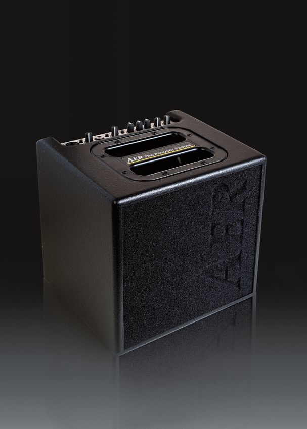
Der Alpha Plus ist unsere Ergänzung zum Alpha und er mit seiner 48-V-Phantomspeisung am XLR-Eingang den
ist bei gleicher Leistung, aber größerem Gehäusevolu- Einsatz von hochwertigen Kondensator-Mikrofonen.
men genauso professionell und vielseitig wie der Alpha Das gesamte System garantiert verzerrungsfreie
selbst. Wiedergabe bei hoher Lautstärke und beeindrucken-
Mit einem Kanal, zwei Eingangsstufen, einer dynamisch der Dynamik, und das bei kleinen Abmessungen und
kontrollierten Leistungsendstufe mit 40 Watt, 8“-Breit- geringem Gewicht.
bandlautsprecher, Dreiband-Klangregelung und Hall Wir wünschen Ihnen viel Spaß beim Einsatz des
verstärkt der Alpha Plus eine große Auswahl von Instru- Alpha!
menten genauso gut wie Gesang.
Alpha
Bedienungsanleitung
Inhalt Seite
1. Einleitung 2
2. Wichtige Sicherheitshinweise 3
3. Bedienungselemente und Anschlüsse 4
3.1 Frontseite 4
3.2 Rückseite 5
4. Inbetriebnahme 6
4.1 Anschließen und Einschalten 6
4.2 Aussteuern 6
5. Funktionsbeschreibung 6
5.1 Klangregelung 6
5.2 Effekte 7
5.3 Footswitch 7
5.4 Phantomspeisung 7
6. Technische Daten 8/9
7. Blockschaltbild 18/19
2
2. Wichtige Sicherheitshinweise
Die folgenden Hinweise dienen der Minimierung des Verletzungsrisikos durch Feuer und Stromschlag.

                                                 Das Blitzsymbol im gleich-             Das Ausrufezeichen im
         C AU T I O N
          RISK OF ELECTRIC SHOCK
                                                 seitigen Dreieck soll den              gleichseitigen Dreieck soll
                DO NOT OPEN                      Benutzer vor unisolierter,             den Benutzer auf wichtige
      AT T E N T I O N                   gefährlicher Spannung innerhalb        Hinweise zu Betrieb und Instand-
      RISQUE DE CHOC ELECTRIQUE
            NE PAS OUVRIR                des Gehäuses dieses Produkts           haltung (Service) dieses Produkts
                                         warnen, die zu einem elektrischen      in den beiliegenden schriftlichen
                                         Schlag führen kann.                    Unterlagen aufmerksam machen.

1. Lesen Sie diese Sicherheitshinweise aufmerksam,              nicht geöffnet werden. Überlassen Sie Wartung,
    bevor Sie das Gerät benutzen.                               Abgleich und Reparatur qualifziertem Fachpersonal.
2. Bewahren Sie diese Sicherheitshinweise sorgfältig auf.       Im Fall eines Fremdeingriffs erlischt die 2-jährige
3. Beachten Sie alle Warnungen, Anweisungen und                 Garantie.
    zusätzliche Aufschriften auf dem Gerät.                  13. Für die Einhaltung der EMV-Forderung müssen
4. Dieses Gerät wurde nur für den Betrieb unter norma-          geschirmte Kabel mit korrekt angeschlossenen
    len klimatischen Bedingungen (gemäßigtes Klima)             Steckverbindern für alle Signalanschlüsse verwendet
    entwickelt.                                                 werden.
5. Installieren und verwenden Sie Ihren Verstärker nicht     14. Verwenden Sie immer einen geerdeten Netzan-
    in der Nähe von Wasser, oder wenn Sie selbst naß             schluß mit der richtigen Netzspannung. Falls Sie
    sind.                                                        Zweifel haben, ob der Anschluß geerdet ist, lassen
6. Setzen Sie Ihr Gerät keinen plötzlichen großen                Sie ihn durch einen qualifzierten Fachmann über-
    Temperaturschwankungen aus. Dies könnte Kon-                 prüfen.
    denswasserbildung im Gerät hervorrufen und es be-        15. Verkabeln Sie Ihren Verstärker nur im ausgeschalte-
    schädigen. Im Fall von Kondenswasserbildung lassen           ten Zustand.
    Sie bitte das Gerät vor der Benutzung vollkommen         16. Dieses Gerät muß in der Nähe einer Netzsteckdose
    austrocknen.                                                eingesetzt werden und sich leicht vom Netz trennen
7. Betreiben Sie Ihr Gerät an einem geschützten Ort, wo         lassen. Der Netzstecker muß ohne weiteres zugäng-
    niemand auf Kabel treten oder über sie stolpern und         lich sein. Achten Sie darauf, daß niemand auf das
    sie beschädigen kann.                                       Netzkabel tritt und daß es nicht eingeklemmt wer-
8. Achten Sie auf eine ungehinderte Belüftung des               den kann, insbesondere an Steckern, Kabelkupplun-
    Verstärkers, verdecken Sie nie Belüftungsöffnungen          gen und an der Stelle, wo es aus dem Gerät austritt.
    oder -gitter.                                            17. Dieses Produkt kann bleibende Hörschäden verur-
9. Ziehen Sie immer den Netzstecker, wenn Sie den               sachen. Betreiben Sie es nicht für längere Zeit mit
    Verstärker reinigen oder für längere Zeit nicht benut-      hoher oder unangenehmer Lautstärke. Falls Sie einen
    zen. Verwenden Sie für die Reinigung ein trockenes          Hörverlust oder Klingeln in den Ohren bemerken,
    Tuch. Vermeiden Sie den Einsatz von Putzmittlen und         sollten Sie einen Ohrenarzt aufsuchen.
    achten Sie darauf, daß keine
                                                             18. Stellen Sie das Produkt nicht in der Nähe von
    Flüssigkeit in das Gerät eindringt.
                                                                Wärme- quellen wie Heizkörpern oder anderen
10. Verwenden Sie nur passende Ersatzsicherungen                Gegenständen, die Wärme abgeben, auf.
    mit gleichem Nennstrom und gleicher Abschaltcha-
    rakteristik. Sicherungen niemals flicken! Ziehen Sie     19. Stellen Sie keine Quellen von offenem Feuer, wie
    vor dem Ersetzen einer Sicherung den Netzstecker.           Kerzen, auf das Gerät.
    Brennt eine Sicherung nach kurzer Zeit erneut durch,     20. Achten Sie darauf, daß keine Gegenstände auf das
    muß das Gerät überprüft werden.                             Gerät fallen und keine Flüssigkeiten durch Öffnun-
11. Installieren Sie Ihren Verstärker nie in der Nähe von       gen in das Gehäuse gelangen. Stellen Sie sicher, daß
    Geräten mit starken elektromagnetischen Feldern,            keine flüssigkeitsgefüllten Gegenstände, wie Vasen,
    wie großen Netztransformatoren, rotierenden                 auf das Gerät gestellt werden.
    Maschinen, Neonbeleuchtung etc. Verlegen Sie             21. Stellen Sie dieses Gerät nicht auf einen
    Signalkabel nicht parallel zu Netzkabeln.                   unstabilen Rollwagen, Ständer, Stativ,
12. Das Innere des Geräts enthält keine durch den               Ausleger oder Tisch. Das Gerät kann her-
    Benutzer zu wartenden Teile. Um eine Gefährdung             unterfallen und ernsthafte Verletzungen
    durch Stromschlag auszuschließen, darf das Gerät            verursachen oder selbst beschädigt werden.

                                                                                                                       3
3. Bedienelemente und Anschlüsse
                             1          2        3        4      5        3        6      7      8       9       10         11       12       13

                            input       line   gain      input    high   gain          colour   bass   middle   treble   efx level           master
                                        mic                       low             clip                                               power

                                               input 1                          input 2                                     alpha plus
IF_AlphaPlus_111217

                      3.1 Frontseite

                      1) input 1                 Eingang, Kombibuchse für XLR oder Klinke (6,35 mm)
                      		                         mit folgenden Anschlußmöglichkeiten:
                      		                        • XLR-Stecker: Mikrofon, symmetrisch, mit 48 V Phantomspeisung
                      		                        • Stereo-Klinkenstecker: Mikrofon, symmetrisch, ohne Phantomspeisung
                      		                         • Mono-Klinkenstecker: Instrument, Line oder Mikrofon,
                      		                           unsymmetrisch, ohne Phantomspeisung
                      2) line/mic                Signalquellen-Wahlschalter der Kombibuchse: line (nur über Klinkenstecker) für
                      		                         Instrumente (Tonabnehmer) und andere line-Quellen, mic für Mikrofone
                      3) gain                    Eingangspegel-Regler
                      4) input 2                 Eingang, Klinkenbuchse 6,35 mm, Instrumenten- oder Line-Eingang
                      5) high/low                Abschwächer, high = Abschwächer aus, low           = Abschwächer an
                      6) clip                    Übersteuerungsanzeige
                                                                                                                    inputs 1 + 2
                      7) colour                  Schalter Klangfarbenfilter     = aus      = ein
                      8) bass                    Basspegel-Regler
                      9) middle                  Mittenpegel-Regler
                      10) treble                 Höhenpegel-Regler

                      11)   efx level            Effektpegel-Regler (reverb)                                                                       effect

                      12) power                  Betriebssanzeige
                      13) master                 Gesamtpegel-Regler (Lautstärke)                                            mains & master

             4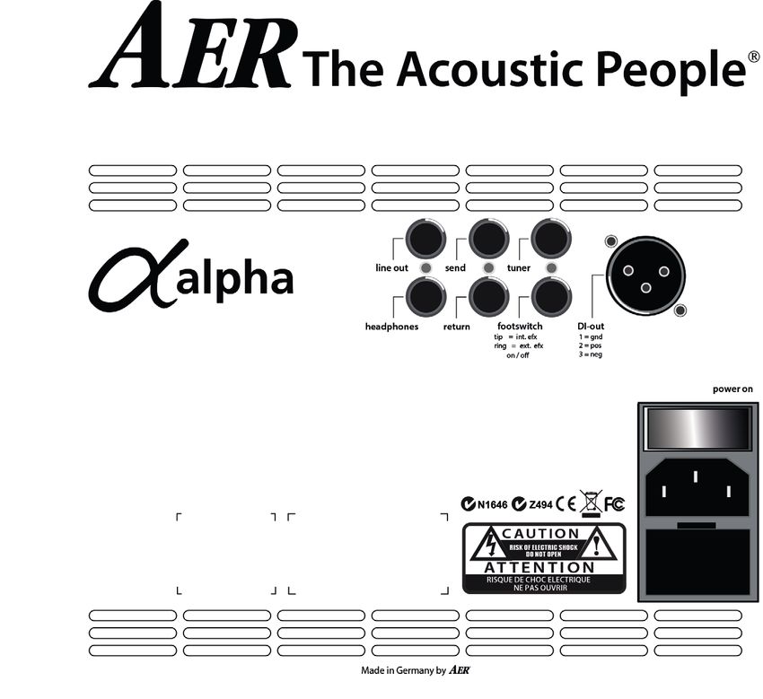
7
                                                    1     3      5

                                                    2     4       6

                                                                                  8

3.2 Rückseite

1)   line out                                           6) footswitch
     Vorverstärkerausgang hinter master                    Anschlußbuchse für einen Doppel-Fußschalter
     und Klangregelung, mit Effekten                       zum Ein- und Ausschalten des eingebauten
                                                           bzw. externen Effekts.
2)   headphones                                            Stereo-Klinkenbuchse, Belegung:
     Kopfhörerausgang. Der Lautsprecher des                Tip = Schalter für den eingebauten Effekt
     Verstärkers wird bei Verwendung dieser Buchse         Ring = Schalter für den externen Effekt
     abgeschaltet.
                                                           (send / return)
                                                        7) DI-out
3) send
                                                           Symmetrischer XLR-Ausgang, vor master,
   Ausgang für einen externen, parallelen                  schaltbar mit oder ohne Effekte
   Effektweg (siehe 5.2) in Verbindung mit return
                                                        8) power
                                                           Netzschalter (ein/aus), kombiniert mit
4) return                                                  Gerätestecker (Typ IEC C14) und Fach für
   Eingang des externen, parallelen Effektwegs.            Netzsicherung (siehe technische Daten).
   Auch allein als Zusatzeingang verwendbar.5)

5) tuner
   Ausgang, vor master, für ein Stimmgerät.

                                                                                                         5
4. Inbetriebnahme
4.1 Anschließen und Einschalten
Prüfen Sie, ob die Netz- • Stellen Sie immer sicher, daß Sie volle Batterien in
spannung vor Ort Ihrem (aktiven) Pickup-System verwenden. Brum-
(z.B. 230 V in Europa, men und Verzerrungen können auch die Folge
120 V in den USA) mit einer leeren Batterie sein.
der zulässigen Netz- • Wenn mehrere Eingänge gleichzeitig in Gebrauch
spannung des Gerätes sind, legen Sie durch die einzelnen gain-Einstel-
übereinstimmt. Die entsprechenden Hinweise und lungen auch das Mischungsverhältnis fest.
Sicherheitssymbole sind auf der Rückseite des Gerä- • Die gain-Regler von unbenutzten Eingängen
tes angegeben. sollten auf Linksanschlag bleiben.
Stellen Sie danach alle gewünschten Kabelverbin-
dungen her und schalten Sie das Gerät ein. Die 5. Funktionsbeschreibung
grüne power-Kontrollleuchte signalisiert Betriebsbe- 5.1 Klangregelung
reitschaft.
Die Klangregelung des Alpha ist eine hochwertige
4.2 Aussteuern Klangbeeinflussung, die den natürlichen Ton von
Instrumenten und Stimme erhält und Ihnen die Mög-
Durch richtiges Aussteuern passen Sie den Alpha lichkeit zur gezielten Akzentuierung bietet.
an Ihre Signalquellen (Gitarren-Tonabnehmer, In Mittelstellung von bass, middle und treble und
Mikrofone, usw.) an. bei nicht gedrückten colour-Schalter verhält sich die
Lassen Sie dazu den master-Regler zunächst auf Klangregelung neutral und beeinflußt den Klang
Linksanschlag stehen nicht.
Bringen Sie den line/mic-Schalter (input 1) in Stel- Bereits in Neutralstellung erzeugt der Verstärker ein
lung mic, wenn Sie ein Mikrofon verwenden. Stellung sehr angenehmes, natürliches Klangbild, das Sie
line eignet sich für Gitarrentonabnehmer aller Art mit dem colour-Filter grundsätzlich färben können.
und die meisten anderen Signalquellen. Dabei werden die Mitten abgesenkt und die Höhen
angehoben. Der Ton wird offener und leichter
Erhöhen Sie nun schrittweise die betreffende gain-
und eignet sich besonders für Zupftechniken. Die
Einstellung gerade so weit, daß die rote clip-Anzeige
Klangregelung kann die Wirkung des colour-Filters
auch bei lautstarkem Spiel noch nicht aufleuchtet.
unterstützen oder mildern (siehe Abb. unten)
Dadurch behalten Sie noch etwas Spielraum für
unerwartete Lautstärkespitzen.
colour bass middle treble
Sehr starke Quellen können trotz niedriger gain-
Einstellung eine clip-Anzeige hervorrufen. Solche
Quellen können Sie zunächst durch Drücken des
high/low-Schalters (input 2) abschwächen.
Stellen Sie zum Schluß mit dem master-Regler die
gewünschte Lautstärke ein. Mit colour-Filter (Schalter gedrückt)
treble absenken um evtl. Schärfe abzumildern.
• Wenn die gain-Einstellung zu niedrig ist, erreicht
der Verstärker nicht die gewünschte Lautstärke,
colour bass middle treble
oder es macht sich störendes Rauschen bemerk-
bar.
• Bei zu hoher Einstellung treten hörbare Verzerrun-
gen (clipping) auf. Durch die clip-Leuchte werden
Sie davor rechtzeitig gewarnt.
Ohne colour-Filter (Schalter nicht gedrückt)
treble anheben um den Ton zu öffnen.
• Wenn das Instrument einen Lautstärke-Regler
besitzt, stellen Sie diesen zum Aussteuern anfangs
Hinweis:
auf höchste Lautstärke. Nehmen Sie ihn aber zu-
rück, falls die clip-Anzeige schon früh aufleuchtet Die Klangregelung wirkt sich auch auf die Aussteu-
und das Aussteuern schwierig ist. erung aus. Falls die clip-Anzeige öfter aufleuchtet,
verringern Sie mit dem gain-Regler die Aussteuerung
etwas (siehe auch 4.2)
65.2 Effekte
Bitte beachten Sie: Für den oben genannten Eingriff
Der Alpha verfügt über einen eingebauten (inter-
muß das Gerät geöffnet werden, deshalb darf die
nen) Hall-Effekt. Der efx-level-Regler bestimmt den
De-/Aktivierung der Phantomspeisung nur in einer
Anteil des gewählten internen Effekts am
Originalsignal (Linksanschlag = kein Effekt). Fachwerkstatt durchgeführt werden.
Darüber hinaus kann ein zusätzliches Effektgerät 9-V-Phantomspeisung am Line-Eingang
(externer Effekt) an den Alpha angeschlossen wer-
den. Benutzen Sie dazu bitte die auf der Rückseite Mit der 9-V-Phantomspeisung können entsprechend
des Gerätes befindlichen Buchsen send und return vorbereitete Instrumenten-Vorverstärker mit Strom
(send zum Input, return vom Output des ext. Effek- versorgt werden (anstelle einer Batterie). Solche
tes). Vorverstärker werden über ein Stereo-Klinkenkabel
Regeln Sie den Effektanteil des eingeschleiften an input 2 angeschlossen.
Effekts am externen Effektgerät. Der externe Signalquellen, die keine Phantomspeisung benöti-
Effektweg arbeitet ’parallel’, d.h. der Effekt wird dem gen, sollten vorsichtshalber immer über ein Mono-
Originalsignal zugemischt. Klinkenkabel (nicht stereo) angeschlossen werden.
Dadurch wird ausgeschlossen, daß die Phantomspan-
5.3 Footswitch nung zur Signalquelle gelangt und diese möglicher-
An die footswitch-Buchse auf der Rückseite des weise beschädigt.
Gerätes kann mit einem Stereokabel ein Standard- Achten Sie auch darauf, daß die Klinkenstecker voll
Doppelfußschalter (An-/Aus-Schalter) angeschlossen (bis zum Anschlag) eingesteckt sind.
werden. Mit diesem werden der interne und
der externe Effekt ein/aus geschaltet.
5.4 Phantomspeisung
48-V-Phantomspeisung am Mikrofoneingang
Mikrofone, die eine 48-V-Phantomspeisung
(P 48) erfordern, können über einen XLR-Stecker
direkt an input 1 angeschlossen werden.
Die 48-V-Phantomspeisung ist im Auslieferungszu- Hinweise zur Benutzung der Phantomspeisung
stand aktiviert, kann aber durch eine interne Steck- Phantomspeisung bedeutet Stromversorgung
brücke deaktiviert werden (siehe Hinweis). eines Audiogeräts (z.B. Mikrofon) über die
Audiokabelverbindung.
Bei Anschluß über Klinkenstecker ist die 48-V
Phantomspeisung nicht wirksam. Verwenden Sie den Schließen Sie an einen Eingang mit (eingeschalteter)
Klinkenanschluß für Mikrofone, die nicht an Phan- Phantomspeisung nur Geräte an,
tomspeisung angeschlossen werden dürfen. die dafür geeignet sind!
Lesen Sie dazu bitte auch die allgemeinen Hinweise Diese Geräte sind entsprechend gekennzeichnet,
achten Sie dabei auch auf die zulässige Stromaufnah-
zur Phantomspeisung.
me (siehe tech. Daten).
Manche Geräte benötigen zwar keine Phantomspei-
sung, können aber damit ‚leben‘.
Bei anderen Geräten, die nicht ausdrücklich für den
Betrieb mit Phantomspeisung entwickelt wurden,
können erhebliche Störungen und auch Schäden
auftreten.
Bei Unsicherheit erkundigen Sie sich bitte beim
Hersteller des von Ihnen verwendeten Geräts!
Wir wünschen Ihnen viel Spaß mit Ihrem Alpha!
76. Technische Daten
input 1 Switchable input with line mode and line out Preamplifier output after master,
microphone mode tone controls, and effects
Combo socket, XLR + jack ¼” (6.35 mm) Mono jack, ¼” (6.35 mm)
line mode (jack input only) Nom. output voltage: 470 mV (–7 dBV)
Line / instrument input, high impedance, Output impedance: 100 Ω
unbalanced Min. load impedance: 2 kΩ
Nom. input voltage: 100 mV (–20 dBV) Residual noise (A-weighted): 5 μV (–106 dBV)
Min. input voltage: 16 mV (–36 dBV) headphones Headphones output. When plugged in,
Max. input voltage: 7 V (+17 dBV) the internal speaker is switched off.
Input impedance: 2 MW || 300 pF Stereo jack, ¼” (6.35 mm)
Signal/noise ratio (A-weighted): 92 dB Nominal, no-load, output voltage:12.7 V (+22 dBV)
Equivalent input noise, Output impedance (per channel): 940 W
A-weighted: 2.4 μV (–112 dBV) Load impedance: 8…2000 W
mic mode (jack or XLR) Nom. output power (THD < 1%): 2 x 1.4 mW / 8 W
Microphone input 2 x 35 mW / 2000 W
XLR (balanced), stereo jack (balanced), Residual noise (A-weighted):
or mono jack (unbalanced) 2.4 μV / 8 W (–112 dBV)
1 / sleeve = ground, 190 μV / 2000 W (–74 dBV)
2 / tip = positive (+), Note: For headphones with stereo (TRS)
3 / ring = negative (–) jack only. Not functional with mono jacks.
Nom. input voltage: 10 mV send Send (output) for effect loop, before
Min. input voltage: 2 mV (–54 dBV) master, after tone controls
with option: 3.5 mV (–49 dBV) (see notes) Mono jack, ¼” (6.35 mm)
Max. input voltage: 1 V (0 dBV) Output voltage: 145 mV (–17 dBV)
with option: 1.6 V (+4 dBV) Output impedance: 47 Ω
Input impedance (balanced): 1.2 kW Min. load impedance: 2 kΩ
Input impedance (unbalanced): 2.7 kW tuner Tuner output
Voice filter: –10 dB at 260 Hz referred to 10 kHz Mono jack, ¼” (6.35 mm)
Signal/noise ratio (A-weighted): 79 dB Nom. output voltage: 145 mV (–17 dBV)
Equivalent input noise, Output impedance: 47 W
A-weighted: 1.1 μV (–119 dBV) Min. load impedance: 2 kΩ
Phantom power: 48 V, XLR only,
R = 6.8 kW per terminal, DI-out Balanced, non-isolated XLR output, after
max. 10 mA total, tone controls, without effects
short-circuit protected 1 = ground,
2 = positive (+),
input 2 Line / instrument input, high impedance, 3 = negative (–)
unbalanced Nom. output voltage (differential):
Mono jack, ¼” (6.35 mm) 60 mV (–24 dBV)
Nom. input voltage: 100 mV (–20 dBV) Output impedance per terminal referred
High / low switch (attenuator): –10 dB to ground: 47 W
Min. input voltage: high: 14 mV (–37 dBV) Min. load impedance (differential): 1 kΩ
low: 43 mV (–27 dBV)
Max. input voltage (THD = 1%) footswitch Connector for a dual footswitch
high: 3.5 V (+11 dBV) Stereo jack, ¼” (6.35 mm)
low: 5 V (+14 dBV) tip = internal effect on/off
Input impedance: 2.2 MW || 300 pF ring = external effect on/off
Signal/noise ratio (A-weighted): 92 dB sleeve = common (ground)
Equivalent input noise, Function: Switch ON = effect OFF
A-weighted: 2.4 μV (–112 dBV) Tone controls
Phantom power: Optional (see notes),
colour –3 dB at 700 Hz, +10 dB at 8 kHz,
9 V DC / max. 100 mA, on ring of input
jack, short circuit protected (input 2) switchable
clip indicator Headroom: -6 dB bass ±8 dB at 100 Hz, shelf type
middle ±6 dB at 800 Hz
return Return (input) from external parallel
effect loop, or supplementary input treble ±8 dB at 10 kHz, shelf type
Mono jack, ¼” (6.35 mm)
Nom. input voltage: 145 mV (–17 dBV)
Max. input voltage 5 V (+14 dBV)
Input impedance: 20 kΩ
86. Technische Daten
Effects Notes
Internal effect Built-in digital reverb Options configurable by internal jumpers (refer modification to
External effect Parallel effect loop, (effect blended with dry qualified personnel):
sound) see send and return. · 9 V phantom power for input 2
Power amp Caution: Phantom power may damage external
Construction Monolithic IC with DMOS output equipment. Read the notes in the operating instructions.
Output power 40 W / 4 ohms (THD = 1%) · Low-gain option (more headroom) for mic input
Continuous output power is determined · Deactivation of 48 V phantom power for mic input
by limiter, see limiter threshold. Definitions
Distortion THD + N < 0.1% (4 W / 4 ohms), Rated conditions
measured at loudspeaker terminals
· Nominal input voltage at input under test
Noise Residual noise (A-weighted SPL):
approx. 16 dB (A) / 1 m · master fully clockwise
See also inputs and outputs for noise specs. · high / low and colour off
Analog signal processing · bass / middle / treble centered
Subsonic filter, adaptive peak limiter · gain of unused inputs and efx level fully anticlockwise
Limiter threshold 35 W / 4 Ω · gain of input under test adjusted to nominal
Speaker system 8” (200 mm) twin cone full-range speaker, output voltage at line out. (This condition corresponds by
bass reflex enclosure design to the rated output power.)
Power supply Mains voltage (depending on model): Nominal input voltage: Standard condition for
100, 120, 230, or 240 V~, 50–60 Hz specifications, if not stated otherwise.
Power consumption: max. 100 W Minimum input voltage: Input voltage required for nominal
Mains fuse Size: 5 x 20 mm output with maximum gain and volume settings.
For 230 and 240 V models: T 1A L 250V Maximum input voltage: Input voltage that does not cause
For 100 and 120 V models: T 2A L 250V distortion more than rated THD+N, suitable control settings
General provided.
Operating temperature range 0…35 °C Nominal output voltage or power refers to rated conditions.
Cabinet 12 mm (0.47”) birch plywood THD + N: Total harmonic distortion + noise, input voltage redu-
ced by 10 dB after setting up rated conditions.
Finish Waterbased acrylic, black spatter finish
Signal / noise ratio: Ratio of output voltage at rated conditions
Dimensions and weight to output noise voltage with input shorted. Equivalent input
Dimensions Height 260 mm (10.24“) noise voltage: Noise voltage at loudspeaker terminals divided by
Width 265 mm (10.43“) gain of amplifier. Input shorted after setting up rated conditions.
Depth 235 mm (9.25“) Residual noise: Output noise with minimal gain and volume
Weight 6.1 kg (13.5 lbs) settings.
Adaptive limiter: Adaptive with respect to power supply.
Maintains constant headroom regardless of power supply
fluctuations.
General: Signal voltages are RMS values. Test signal sine 1 kHz
sine unless stated otherwise. Noise measured from 20 Hz to 20
kHz. Noise stated for a specific input implies that all other inputs
are not used. Sound pressure level (SPL) based on loudspeaker
specification by manufacturer.
Specifications and appearance subject to change without notice.
TD2016051
Alpha (Modell 2010)
Versionsinformation:
Diese technischen Daten setzen voraus:
Leiterplatte Board 1 Rev. D, Vers. 5 (EAGLE-Dateien
5091104D_5*)
Leiterplatte Board 2 Rev. C, Vers. 1 (EAGLE-Dateien
5091201C_1*)
Netztrafo Noratel
Daten meßtechnisch geprüft: 11_05_2016 HHB
91. Introduction
Welcome to AER!
Thank you for choosing the Alpha .
The Alpha is a professional, compact and powerful amp-
lifier system. Especially developed for the enhanement of
acoustic instruments, it is as well suitable for other (also Alpha Plus provide you with a well-balanced tone at all
electrical) instruments. sound pressure levels.
With one channel but two independant input stages All AER-systems are subtly dynamically controlled,
(line and microphone/line) the Alpha offers you various which ensures absolute reliability in full load opera-
options in signal processing. tion despite strikingly small sizes and little weight.
40 Watts Plus the 8“-twin cone speaker system of the Read on and have fun using your Alpha!
Alpha
User Manual
Content Page
1. Introduction 10
2. Important Safety Instructions 11
3. Controls and connections 12
3.1 Front side 12
3.2 Rear side 13
4. Starting up 14
4.1 Cabling and switching on 14
4.2 Level adjustment 14
5. Functional characteristics 15
5.1 Tone control 15
5.2 Effects 15
5.3 Footswitch 15
5.4 Phantom powering 15
6. Technical specifications 16/17
7. Circuit diagram 18/19
102. Important Safety Instructions
The following guidelines shall help minimize the risk of injury through fire or electric shock.
The lightning flash with The exclamation point
C AU T I O N the arrow head symbol within an equilateral
RISK OF ELECTRIC SHOCK
DO NOT OPEN within an equilateral triangle is intended to
AT T E N T I O N triangle is intended to alert the alert the user to the presence
RISQUE DE CHOC ELECTRIQUE user to the presence of unisolated of important operating and
NE PAS OUVRIR
´dangerous voltage´ within this maintenance (servicing)
product´s enclosure that may instructions in the literature
be of sufficient magnitude to accompanying this product.
constitute a risk of electric shock
to persons.
1. Carefully read these safety notes before you use the staff only. Any unauthorized tampering will void the
device! 2-year warranty.
2. Keep these safety notes in a safe place. 13. In keeping with the EMV regulations screened cables
3. Pay attention to all warnings, instructions and additi- with correctly fitted connectors must be used for all
onal texts on the unit. signal connections.
4. This device was only designed for operation under 14. Always use an earthed power supply with the
normal climatic conditions (temperate climate). correct mains voltage. If you are in doubt about the
power outlet ground, have it checked by a qualified
5. Do not install or use your amp in close proximity to
technician.
water or if you are wet yourself.
15. Cable up your amp only when it is powered off.
6. Do not subject your device to sudden and severe
temperature changes. This could cause moisture 16. This device should be installed near the socket out-
condensation inside the unit, which could damage let and disconnection of the device should be easily
it. In the event of moisture condensation allow the accessible. The mains plug of the power
device to dry out completely before use. supply shall remain readily operable. Protect the
power cord from being walked on or pinched par-
7. Use your amp in a safe place where nobody can step ticularly at plugs, convenience receptacles and the
on cables or trip over and damage them. point where they exit from the apparatus.
8. Pay attention to an unhindered air circulation 17. This product may cause permanent hearing loss.
around the amp, never obstruct the air vents or grilles. Do not operate for long periods of time at a high
9. Always pull the mains plug before cleaning your volume level or at any level that is uncomfortable.
amp or when left unused for a long period of time. If you experience any hearing loss or ringing in the
Use only a dry cloth for cleaning. Avoid the use of ears, you should consult an audiologist.
detergents and do not let any liquids seep into the 18. The product should be located away from heat
unit. sources such as radiators, heat registers or other
10. Use only the right fuses with the same current products that produce heat.
rating and trigger characteristic as replacements. Ne- 19. Do not place any open sources of fire, like candles,
ver mend fuses! Pull the mains plug before replacing on the device.
a fuse. Should a fuse blow again after a short while,
20. Care should be taken so that objects do not fall onto
the device needs to be checked.
the device and liquids are not spilled into the enclo-
11. Never install your amp close to devices with strong sure through openings. Ensure that no objects filled
electromagnetic fields such as large mains transfor- with liquids, such as vases, are placed on the device.
mers, revolving machines, neon illumination etc. Do
21. Do not place this device on an unstable cart, stand,
not lay signal cables parallel to power current cables.
tripod, bracket or table. The device may fall, causing
12. There are no user-serviceable components inside the serious injury to you and serious damage
unit. To avoid the risk of an electric shock, the unit to the device itself.
must not be opened. All maintenance, adjustment
and repair works should be carried out by qualified
113. Controls and connections
1 2 3 4 5 3 6 7 8 9 10 11 12 13
input line gain input high gain colour bass middle treble efx level master
mic low clip power
input 1 input 2 alpha plus
IF_AlphaPlus_111217
3.1 Front side
1) input Input 1, combo socket for ¼“ (6.35 mm) jack or XLR, with
following connection options:
• XLR connector: microphone, balanced, with 48 V phantom power
• stereo jack connector: microphone, balanced, without phantom power
• mono jack connector: instrument, line, or microphone, unbalanced,
without phantom power.
2) line/mic signal source selector switch: line (only via jackplug)
for instruments (pickup) and other line level sources,
mic (only via XLR-connector) for microphones
3) gain input level control
4) input (Input 2) signal input, socket for 6,3 mm mono jackplug inputs 1 + 2
5) high/low attenuator, high = att. off, low = att. on
6) clip overload indicator
7) colour tone colour filter activation switch = not active, = active
8) bass bass level control
9) middle middle level control
10) treble treble level control
11) efx level effect level control (reverb) effect
12) power on/off status indicator
13) master master level control (volume) mains & master
127
1 3 5
2 4 6
8
3.2 Rear side
1) line out 5) tuner
Preamplifier output post master and tone Output, pre master, for a tuner.
controls, with effects 6) footswitch
2) headphones Connector for a dual footswitch switching the
Output for headphones. The loudspeaker of internal and external effect on/off.
the amplifier is switched off when this socket Stereo jack socket, assignment:
is used. Tip = switch for internal effect
3) send Ring = switch for external effect (send / return)
Output for external, parallel effect loop (see 7) DI-out
5.2) in conjunction with return Balanced XLR output, pre master, switchable
4) return with or without effects.
Input of the external, parallel effect path 8) power
Can also be used alone as an additional Power on/off switch, combined with mains inlet
input. (IEC C14 type) and compartment for mains fuse
(see technical data).
134. Starting up
4.1 Cabling and switching on
• If several inputs are used simultaneously, you also
Before connecting to
determine the mixing ratio by the individual gain
mains, please ensure
settings.
that your local mains
voltage is suitable for
the voltage of the device • The gain controls of any unused inputs should
(e.g. 120V in the USA, stay fully anticlockwise.
230V in Europe). The
relevant specs and safety symbols are printed on the 5. Functional characteristics
rear side of the unit.
5.1 Tone control
Connect all cables according to your application and
switch the amplifier on. The green power control LED The tone controls of the Alpha are a high-quality
indicates operational readiness. sound modification tool that preserves the natural
tone of instruments and voice and allows you to
4.2 Level adjustment apply targeted accentuations.
By proper level adjustment you adapt the Alpha If bass, middle, and treble are in center position and
to your signal sources (guitar pick-ups, the colour switch is not pushed, the tone controls are
microphones, etc.). neutral and have no influence on the sound.
For this purpose keep the master control initially fully The amplifier will already provide a very pleasant, na-
anticlockwise. tural sound when all controls are in neutral position,
Set the line/mic switch (input 1) to position mic if you which you can then principally alter with the colour
are using a microphone. Position line is suitable for filter: This will reduce the midrange and bring out the
all types of guitar pickups and most other sources. trebles. The sound becomes more open and lighter
and is particularly suitable for finger picking tech-
Now gradually increase the appropriate gain setting niques. The tone controls can support or attenuate
as far as possible but without triggering the red clip the effect of the colour filter (see illustration below).
indicator, even when you play loud. Thereby you
keep some headroom for unexpected peak levels.
Very strong sources may cause a clipping warning colour bass middle treble With colour-filter
despite a low gain setting. Such sources can be (switch pressed)
attenuated first by pushing the high/low switch reduce treble
(input 2). to soften possible
Finally set the desired volume using the master harshness.
control.
• If the gain setting is too low, the amplifier may not colour bass middle treble Without colour-filter
reach the desired volume, or distracting noise may (switch not pressed)
become noticeable. boost treble
to brighten the
• Setting the gain too high causes distorted sound sound.
(clipping). The clip light will warn you before this
happens.
• If you use an instrument with a volume control,
start off with full volume but reduce it if the clip
indicator lights up early and the level adjustment Please note:
is difficult.
The tone controls have an effect on the signal level.
• Please ensure there is always enough battery If the clip indicator flashes more frequently, reducet
power in your (active) pick-up system. Humming he level a bit using the gain control (see also 4.2)
and sizzling may be caused by an empty battery.
145.2 Effect
9 V phantom power at line input
The Alpha has a built-in (internal)
The 9 V phantom power supplies instrument
reverb-effect. The efx-level-control determines the
preamps with power (instead of a battery) that are
intensity of the internal effects (left stop = no effect).
prepared accordingly. Such preamps are connected
Furthermore an additional effects unit (external ef-
to input 1 by a stereo jack cable.
fect) may be connected to the Alpha. For this purpo-
se use the send and return sockets on the rear side The phantom power can be switched on by the 9 V
of the amplifier (send goes to input, return to the switch. The yellow indicator lamp then lights up.
output of the external effects device). The intensity Sources that don‘t need phantom power should
of the effect is adjusted at the external effects unit. always be connected via a mono jack cable (not
The external effect loop works „parallel“, the effect is stereo) as a precaution. This way the phantom power
blended with the original signal. cannot get to the source and possibly damage it.
Also make sure that the plugs are fully plugged in.
5.3 Footswitch
A standard double-footswitch (on-/off-switch) can be Notes on the use of phantom power
plugged into the footswitch-socket on the rear side
Phantom power means remote power supply of an
of the amplifier via stereo cable. By this footswitch
audio device (e.g. microphone) via the audio line.
the internal and external effects can be switched on
and off. Only suitable devices should be connected to an
input with (activated) phantom power.
Suitable footswitches are on-off toggle switches,
Such devices are also marked accordingly.
which are turned on by stepping once, and turned off
Please heed the permissible power consumption
by stepping once again. (see technical data).
Some devices do not need phantom power
5.4 Phantom power but tolerate it.
48 V phantom power at microphone input Other devices that have not been designed
Microphones that require 48 V phantom power explicitly for phantom power operation can
(P 48) can be connected directly to mic in by an XLR suffer from considerable malfunction and damage
plug. The amplifier is supplied with 48 V phantom may result as well.
power enabled, but it can be disabled by an internal In case of uncertainty please consult the
jumper (see note). manufacturer of your accessories.
When connected by a jack plug, the 48 V phantom
power is not applied. Use the jack connection for mi- We wish you lots of fun playing your Alpha!
crophones that must not be connected to phantom
power.
Please also read the general notes on
phantom power.
Please note: For the alteration mentioned above,
the device must be opened, therefore only qualified
personnel may carry out the de-/activation of the
phantom power.
156. Technical specifications
input 1 Switchable input with line mode and line out Preamplifier output after master,
microphone mode tone controls, and effects
Combo socket, XLR + jack ¼” (6.35 mm) Mono jack, ¼” (6.35 mm)
line mode (jack input only) Nom. output voltage: 470 mV (–7 dBV)
Line / instrument input, high impedance, Output impedance: 100 Ω
unbalanced Min. load impedance: 2 kΩ
Nom. input voltage: 100 mV (–20 dBV) Residual noise (A-weighted): 5 μV (–106 dBV)
Min. input voltage: 16 mV (–36 dBV) headphones Headphones output. When plugged in,
Max. input voltage: 7 V (+17 dBV) the internal speaker is switched off.
Input impedance: 2 MW || 300 pF Stereo jack, ¼” (6.35 mm)
Signal/noise ratio (A-weighted): 92 dB Nominal, no-load, output voltage:12.7 V (+22 dBV)
Equivalent input noise, Output impedance (per channel): 940 W
A-weighted: 2.4 μV (–112 dBV) Load impedance: 8…2000 W
mic mode (jack or XLR) Nom. output power (THD < 1%): 2 x 1.4 mW / 8 W
Microphone input 2 x 35 mW / 2000 W
XLR (balanced), stereo jack (balanced), Residual noise (A-weighted):
or mono jack (unbalanced) 2.4 μV / 8 W (–112 dBV)
1 / sleeve = ground, 190 μV / 2000 W (–74 dBV)
2 / tip = positive (+), Note: For headphones with stereo (TRS)
3 / ring = negative (–) jack only. Not functional with mono jacks.
Nom. input voltage: 10 mV send Send (output) for effect loop, before
Min. input voltage: 2 mV (–54 dBV) master, after tone controls
with option: 3.5 mV (–49 dBV) (see notes) Mono jack, ¼” (6.35 mm)
Max. input voltage: 1 V (0 dBV) Output voltage: 145 mV (–17 dBV)
with option: 1.6 V (+4 dBV) Output impedance: 47 Ω
Input impedance (balanced): 1.2 kW Min. load impedance: 2 kΩ
Input impedance (unbalanced): 2.7 kW tuner Tuner output
Voice filter: –10 dB at 260 Hz referred to 10 kHz Mono jack, ¼” (6.35 mm)
Signal/noise ratio (A-weighted): 79 dB Nom. output voltage: 145 mV (–17 dBV)
Equivalent input noise, Output impedance: 47 W
A-weighted: 1.1 μV (–119 dBV) Min. load impedance: 2 kΩ
Phantom power: 48 V, XLR only,
R = 6.8 kW per terminal, DI-out Balanced, non-isolated XLR output, after
max. 10 mA total, tone controls, without effects
short-circuit protected 1 = ground,
2 = positive (+),
input 2 Line / instrument input, high impedance, 3 = negative (–)
unbalanced Nom. output voltage (differential):
Mono jack, ¼” (6.35 mm) 60 mV (–24 dBV)
Nom. input voltage: 100 mV (–20 dBV) Output impedance per terminal referred
High / low switch (attenuator): –10 dB to ground: 47 W
Min. input voltage: high: 14 mV (–37 dBV) Min. load impedance (differential): 1 kΩ
low: 43 mV (–27 dBV)
Max. input voltage (THD = 1%) footswitch Connector for a dual footswitch
high: 3.5 V (+11 dBV) Stereo jack, ¼” (6.35 mm)
low: 5 V (+14 dBV) tip = internal effect on/off
Input impedance: 2.2 MW || 300 pF ring = external effect on/off
Signal/noise ratio (A-weighted): 92 dB sleeve = common (ground)
Equivalent input noise, Function: Switch ON = effect OFF
A-weighted: 2.4 μV (–112 dBV) Tone controls
Phantom power: Optional (see notes),
colour –3 dB at 700 Hz, +10 dB at 8 kHz,
9 V DC / max. 100 mA, on ring of input
jack, short circuit protected (input 2) switchable
clip indicator Headroom: -6 dB bass ±8 dB at 100 Hz, shelf type
middle ±6 dB at 800 Hz
return Return (input) from external parallel
effect loop, or supplementary input treble ±8 dB at 10 kHz, shelf type
Mono jack, ¼” (6.35 mm)
Nom. input voltage: 145 mV (–17 dBV)
Max. input voltage 5 V (+14 dBV)
Input impedance: 20 kΩ
166. Technical specifications
Effects Notes
Internal effect Built-in digital reverb Options configurable by internal jumpers (refer modification to
External effect Parallel effect loop, (effect blended with dry qualified personnel):
sound) see send and return. · 9 V phantom power for input 2
Power amp Caution: Phantom power may damage external
Construction Monolithic IC with DMOS output equipment. Read the notes in the operating instructions.
Output power 40 W / 4 ohms (THD = 1%) · Low-gain option (more headroom) for mic input
Continuous output power is determined · Deactivation of 48 V phantom power for mic input
by limiter, see limiter threshold. Definitions
Distortion THD + N < 0.1% (4 W / 4 ohms), Rated conditions
measured at loudspeaker terminals
· Nominal input voltage at input under test
Noise Residual noise (A-weighted SPL):
approx. 16 dB (A) / 1 m · master fully clockwise
See also inputs and outputs for noise specs. · high / low and colour off
Analog signal processing · bass / middle / treble centered
Subsonic filter, adaptive peak limiter · gain of unused inputs and efx level fully anticlockwise
Limiter threshold 35 W / 4 Ω · gain of input under test adjusted to nominal
Speaker system 8” (200 mm) twin cone full-range speaker, output voltage at line out. (This condition corresponds by
bass reflex enclosure design to the rated output power.)
Power supply Mains voltage (depending on model): Nominal input voltage: Standard condition for
100, 120, 230, or 240 V~, 50–60 Hz specifications, if not stated otherwise.
Power consumption: max. 100 W Minimum input voltage: Input voltage required for nominal
Mains fuse Size: 5 x 20 mm output with maximum gain and volume settings.
For 230 and 240 V models: T 1A L 250V Maximum input voltage: Input voltage that does not cause
For 100 and 120 V models: T 2A L 250V distortion more than rated THD+N, suitable control settings
General provided.
Operating temperature range 0…35 °C Nominal output voltage or power refers to rated conditions.
Cabinet 12 mm (0.47”) birch plywood THD + N: Total harmonic distortion + noise, input voltage redu-
ced by 10 dB after setting up rated conditions.
Finish Waterbased acrylic, black spatter finish
Signal / noise ratio: Ratio of output voltage at rated conditions
Dimensions and weight to output noise voltage with input shorted. Equivalent input
Dimensions Height 260 mm (10.24“) noise voltage: Noise voltage at loudspeaker terminals divided by
Width 265 mm (10.43“) gain of amplifier. Input shorted after setting up rated conditions.
Depth 235 mm (9.25“) Residual noise: Output noise with minimal gain and volume
Weight 6.1 kg (13.5 lbs) settings.
Adaptive limiter: Adaptive with respect to power supply.
Maintains constant headroom regardless of power supply
fluctuations.
General: Signal voltages are RMS values. Test signal sine 1 kHz
sine unless stated otherwise. Noise measured from 20 Hz to 20
kHz. Noise stated for a specific input implies that all other inputs
are not used. Sound pressure level (SPL) based on loudspeaker
specification by manufacturer.
Specifications and appearance subject to change without notice.
TD2016051
Alpha (Modell 2010)
Versionsinformation:
Diese technischen Daten setzen voraus:
Leiterplatte Board 1 Rev. D, Vers. 5 (EAGLE-Dateien
5091104D_5*)
Leiterplatte Board 2 Rev. C, Vers. 1 (EAGLE-Dateien
5091201C_1*)
Netztrafo Noratel
Daten meßtechnisch geprüft: 11_05_2016 HHB
177. Blockschaltbild/Circuit diagram
CLIP DETECTION
INPUT 1
PREAMP GAIN 1
LINE LINE
R T MIC MIC
MIC GAIN H/L
PREAMP VOICE
1
2
3
6.8k
6.8k
48V PHANTOM POWER
+48V
BASS MIDDLE TRE
9V PHANTOM POWER
CLIP DETECTION
+9V
INPUT 2
GAIN 2 COLOUR
PREAMP
CLIP D
R T
HIGH/LOW
OFF/ON
182
3 1 DI-out
TUNER
SEND
EFFECT
FX
T R FOOTSWITCH
RETURN
CLIP DETECTION
LINE
EBLE
MASTER
470R HEADPHONES
SUBSONIC LIMITER POWER AMP T R
DUAL CONE SPEAKER
CLIP DETECTION
DETECTION CLIP
B09217D_20160919
19Sales Version: 00800122 Sales
Europe Africa, America, Asia, Oceania
aer music gmbh aer amplifier gmbh
Haberstrasse 46 Haberstrasse 46
D-42551 Velbert D-42551 Velbert
info@aer-music.de info@aer-amplifier.com
www.aer-music.de
20Sie können auch lesen