User Guide Mode d'emploi Bedienungsanleitung - www.focusrite.com
←
→
Transkription von Seiteninhalten
Wenn Ihr Browser die Seite nicht korrekt rendert, bitte, lesen Sie den Inhalt der Seite unten

User Guide
Mode d’emploi
Bedienungsanleitung

 FA0540-01            www.focusrite.com
English

          IMPORTANT SAFETY INSTRUCTIONS
              1.     Read these instructions.
              2.     Keep these instructions.
              3.     Heed all warnings.
              4.     Follow all instructions.
              5.     Do not use this apparatus with water.
              6.     Clean only with dry cloth.
              7.     Install in accordance with the manufacturer’s instructions.
              8.     Do not install near any heat sources such as radiators, heat registers, stoves, or other apparatus (including amplifiers)
                     that produce heat.
              9.     Do not defeat the safety purpose of the polarized or grounding-type plug. A polarized plug has two blades with
                     one wider than the other. A grounding type plug has two blades and a third grounding prong. The wide blade or the
                     third prong are provided for your safety. If the provided plug does not fit into your outlet, consult an electrician for
                     replacement of the obsolete outlet.
              10.    Protect the power cord from being walked on or pinched particularly at plugs, convenience receptacles, and the point
                     where they exit from the apparatus.
              11.    Only use attachments/accessories specified by the manufacturer.
              12.    Use only with the cart, stand, tripod, bracket, or table specified by the manufacturer, or sold with the apparatus. When a
                     cart is used, use caution when moving the cart/apparatus combination to avoid injury from tip-over.

              13.    Unplug this apparatus during lightning storms or when unused for long periods of time.
              14.    Refer all servicing to qualified service personnel. Servicing is required when the apparatus has been damaged in any
                     way, such as power-supply cord or plug is damaged, liquid has been spilled or objects have fallen into the apparatus, the
                     apparatus has been exposed to rain or moisture, does not operate normally, or has been dropped.
              15.    No naked flames, such as lighted candles, should be placed on the apparatus.
          WARNING: To reduce the risk of fire or electric shock, do not expose this apparatus to rain or moisture.
          It is important that the apparatus shall not be exposed to dripping or splashing and that no objects filled with liquids, such as
          vases shall be placed on the apparatus.
          •      Do not expose this apparatus to drips or splashes.
          •      Do not place any objects filled with liquids, such as vases, on the apparatus.
          •      Do not install this apparatus in a confined space such as a bookcase or similar unit.
          •      Slots and openings in the cabinet are provided for ventilation and to ensure reliable operation of the product and to
                 protect it from overheating. Please ensure adequate space around the apparatus for sufficient ventilation. Ventilation
                 should not be impeded by covering the ventilation openings with items such as newspapers, tablecloths curtains etc.
          •      The apparatus draws nominal non-operating power from the AC outlet with its POWER switch in the off position.
          •      The apparatus should be located close enough to the AC outlet so that you can easily grasp the power cord plug at any
                 time.
          •      An apparatus with Class 1 construction shall be connected to an AC outlet with a protective grounding connection.
          •      The MAINS plug or the appliance coupler is used as the disconnect device. Either device shall remain readily operable
                 when the apparatus is installed for use.
          •      No naked flames, such as lighted candles, should be placed on the apparatus.
          WARNING: Excessive sound pressure levels from earphones and headphones can cause hearing loss.
                                                                The exclamation point within an equilateral triangle is intended to
                                                                alert the user to the presence of important operating and maintenance
                                                                (servicing) instructions in the literature accompanying the appliance.

                                                               CAUTION: TO REDUCE THE RISK OF ELECTRIC SHOCK, DO NOT REMOVE
                                                               COVER (OR BACK). NO USER-SERVICEABLE PARTS INSIDE.
                                                               REFER SERVICING TO QUALIFIED SERVICE PERSONNEL.

                                                                The lightning flash with arrowhead symbol, within equilateral triangle,
                                                                is intended to alert the user to the presence of uninsulated “dangerous
                                                                voltage” within the product’s enclosure that may be of sufficient magnitude
                                                                to constitute a risk of electric shock to persons.

            GB       This equipment must be earthed by the power cord
            FIN      Laite on liitettävä suojamaadoituskoskettimilla varustettuun pistorasiaan
          NOR        Apparatet må kun tilkoples jordet stikkontakt
          SWE        Apparaten skall ansultas till jordat uttag

          2
English
ENVIRONMENTAL DECLARATION
Compliance Information Statement: Declaration of Compliance procedure
Product Identification: Focusrite ISA Two
Responsible party: American Music and Sound
Address: 5304 Derry Avenue #C
Agoura Hills,
CA 91301
Telephone: 800-994-4984
This device complies with part 15 of the FCC Rules. Operation is subject to the following two conditions: (1) This device may not cause
harmful interference, and (2) this device must accept any interference received, including interference that may cause undesired
operation.
For USA
To the User:
1. Do not modify this unit! This product, when installed as indicated in the instructions contained in
this manual, meets FCC requirements. Modifications not expressly approved by Focusrite may void your
authority, granted by the FCC, to use this product.
2. Important: This product satisfies FCC regulations when high quality shielded cables are used to connect
with other equipment. Failure to use high quality shielded cables or to follow the installation instructions
within this manual may cause magnetic interference with appliances such as radios and televisions and
void your FCC authorization to use this product in the USA.
3. Note: This equipment has been tested and found to comply with the limits for a Class B digital device,
pursuant to part 15 of the FCC Rules. These limits are designed to provide reasonable protection against
harmful interference in a residential installation. This equipment generates, uses and can radiate radio
frequency energy and, if not installed and used in accordance with the instructions, may cause harmful
interference to radio communications. However, there is no guarantee that interference will not occur in a
particular installation. If this equipment does cause harmful interference to radio or television reception,
which can be determined by turning the equipment off and on, the user is encouraged to try to correct the
interference by one or more of the following measures:
• Reorient or relocate the receiving antenna.
• Increase the separation between the equipment and receiver.
• Connect the equipment into an outlet on a circuit different from that to which the receiver
is connected.
• Consult the dealer or an experienced radio/TV technician for help.
For Canada
To the User:
This Class B digital apparatus complies with Canadian ICES-003.
Cet appareil numérique de la classe B est conforme à la norme NMB-003 du Canada.
RoHS Notice
Focusrite Audio Engineering Limited has conformed and [its/this] product[s] conform[s], where applicable, to the European Union’s
Directive 2002/95/EC on Restrictions of Hazardous Substances (RoHS) as well as the following sections of California law which refer to
RoHS, namely sections 25214.10, 25214.10.2, and 58012, Health and Safety Code; Section 42475.2, Public Resources Code.
3English
TABLE OF CONTENTS
IMPORTANT SAFETY INSTRUCTIONS . . . . . . . . . . . . . . . . . . . . . . . . . . . . . . . . . . . . . . . . . . . . . . . 2
TABLE OF CONTENTS . . . . . . . . . . . . . . . . . . . . . . . . . . . . . . . . . . . . . . . . . . . . . . . . . . . . . . . . . . . . 4
OVERVIEW . . . . . . . . . . . . . . . . . . . . . . . . . . . . . . . . . . . . . . . . . . . . . . . . . . . . . . . . . . . . . . . . . . . . . 5
Introduction . . . . . . . . . . . . . . . . . . . . . . . . . . . . . . . . . . . . . . . . . . . . . . . . . . . . . . . . . . . . . . . . . 5
Features . . . . . . . . . . . . . . . . . . . . . . . . . . . . . . . . . . . . . . . . . . . . . . . . . . . . . . . . . . . . . . . . . . . . 5
Box Contents . . . . . . . . . . . . . . . . . . . . . . . . . . . . . . . . . . . . . . . . . . . . . . . . . . . . . . . . . . . . . . . . 5
GETTING STARTED AND POWERING UP . . . . . . . . . . . . . . . . . . . . . . . . . . . . . . . . . . . . . . . . . . . . 6
HARDWARE FEATURES . . . . . . . . . . . . . . . . . . . . . . . . . . . . . . . . . . . . . . . . . . . . . . . . . . . . . . . . . . 7
Front Panel . . . . . . . . . . . . . . . . . . . . . . . . . . . . . . . . . . . . . . . . . . . . . . . . . . . . . . . . . . . . . . . . . 7
Front Panel Sections . . . . . . . . . . . . . . . . . . . . . . . . . . . . . . . . . . . . . . . . . . . . . . . . . . . . . . . . . 7
Rear Panel . . . . . . . . . . . . . . . . . . . . . . . . . . . . . . . . . . . . . . . . . . . . . . . . . . . . . . . . . . . . . . . . . 10
Rear Panel Sections . . . . . . . . . . . . . . . . . . . . . . . . . . . . . . . . . . . . . . . . . . . . . . . . . . . . . . . . . 10
APPLICATIONS . . . . . . . . . . . . . . . . . . . . . . . . . . . . . . . . . . . . . . . . . . . . . . . . . . . . . . . . . . . . . . . . 12
Switchable Impedance: In Depth Explanation . . . . . . . . . . . . . . . . . . . . . . . . . . . . . . . . . . . . 12
EXAMPLE OF USAGE . . . . . . . . . . . . . . . . . . . . . . . . . . . . . . . . . . . . . . . . . . . . . . . . . . . . . . . . . . . . 14
SPECIFICATIONS . . . . . . . . . . . . . . . . . . . . . . . . . . . . . . . . . . . . . . . . . . . . . . . . . . . . . . . . . . . . . . 15
Performance Specifications . . . . . . . . . . . . . . . . . . . . . . . . . . . . . . . . . . . . . . . . . . . . . . . . . . . 15
Physical and Electrical Characteristics . . . . . . . . . . . . . . . . . . . . . . . . . . . . . . . . . . . . . . . . . 17
WARRANTY . . . . . . . . . . . . . . . . . . . . . . . . . . . . . . . . . . . . . . . . . . . . . . . . . . . . . . . . . . . . . . . . . . . 18
ACCURACY . . . . . . . . . . . . . . . . . . . . . . . . . . . . . . . . . . . . . . . . . . . . . . . . . . . . . . . . . . . . . . . . . . . . 18
COPYRIGHT . . . . . . . . . . . . . . . . . . . . . . . . . . . . . . . . . . . . . . . . . . . . . . . . . . . . . . . . . . . . . . . . . . . 18
4English
OVERVIEW
Introduction
The ISA Two provides two of Focusrite’s prestigious transformer-based microphone preamps. It
features the same classic circuitry and renowned audio quality found in the original at a new level
of affordability. With selectable input impedance, direct instrument inputs and insert points, the ISA
Two creates the perfect front end for the discerning recording professional.
First introduced in 1985, the ISA microphone preamp holds a reputation for outstanding transparency
along with subtle warmth contributed by transformer core saturation. The addition of a variable
impedance circuit allows ISA users to perfectly match the preamp with any microphone, or to use
different settings creatively to shape the sound of the microphone. Unchanged for decades, the ISA
microphone preamp topology offers incredible clarity and the signature Focusrite sound that makes
it the top choice among many audio professionals today.
Features
• Two ISA series transformer-based preamps
• Selectable input impedance
• Two front panel instrument inputs
• Dedicated analogue insert points
• Variable high pass filter
Box Contents
• ISA Two
• IEC Power cable
• Printed User Guide in English, French and German
5English
GETTING STARTED AND POWERING UP
The ISA Two is a high quality two-channel preamplifier, which can be used to record microphone,
line-level and instrument sources. Microphones and line-level sources are connected at the rear
panel, whilst instruments are plugged directly into the front panel. The front panel also has gain
controls and other controls such as phantom power and input impedance selection. LED peak meters
are provided, with a calibration control at the rear panel, to ensure a suitable signal level is achieved.
An on-off switch on the front panel applies power to the unit, providing the supplied IEC mains lead is
connected to the socket on the rear. Please make sure that the ISA Two is turned on before powering
any devices connected to the outputs.
The IEC mains lead supplied with the unit should have the correct moulded plug for your country.
The wiring colour code used is:
Live Neutral Earth
For units shipped to the USA, Canada, Taiwan and Japan: Black White Green
For units shipped to any other country: Brown Blue Green and Yellow
6English
HARDWARE FEATURES
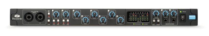
Front Panel
6 3 8 6 3 8
12 1 7 5 2 4 9 10 1 7 5 2 4 9 10 11
1. Input switch: selects the input source (mic, line or instrument)
2. Gain control: sets the gain of the input signal in stepped values of 10 dB
3. 30-60 switch: selects the range of the Gain control (0 to +30 dB, or +30 to +60 dB). The default
range is 0 to +30 dB
4. Trim control: allows an additional 20 dB of gain to be applied to a mic/line-level signal, or can
be used as a gain control for the Instrument Inputs
5. Phantom power switch: supplies +48 V to the corresponding mic input on the rear panel
6. Z In switch: sets the mic input impedance to 600 Ω (Low), 1.4 kΩ (ISA 110), 2.4 kΩ (Med) or
6.8 kΩ (High)
7. Phase switch: inverts the phase of the signal
8. Filter switch: activates a high pass filter (HPF)
9. Filter control: selects the frequency of the high pass filter between 16 Hz-420 Hz
10. Insert: allows the signal to be sent to additional external processors (via the send and return
connectors on the rear panel) prior to the output
11. Peak LED meters: show the main output levels in dBFS
12. Instrument Inputs: for connecting high impedance instruments such as guitars
Front Panel Sections
Input (1)
Pressing Input steps through each of the three inputs, as indicated by the corresponding LEDs.
When the Mic LED is lit, the microphone input is active. An XLR input for a microphone, as well as
3-pole (TRS) ¼” inputs for line-level sources, can be found on the rear panel. A 2-pole (TS) ¼” input
for an instrument (DI) is available on the front panel.
Mic input gain (2)
With the mic input selected, the user has access to the full gain range in 10 dB steps from 0 dB to
+60 dB. The range of operation of the gain control is determined by the setting of the mic gain range
switch (3) - see following page:
7English
Mode 1: Mic Gain Range 0-30
With the 30-60 switch (3) off, the stepped Gain control operates over a gain range of 0 dB to +30
dB, the gain setting being indicated on the front panel by the outer arc of numbers around the Gain
control.
Mode 2: Mic Gain Range 30-60
With the 30-60 switch (3) on (illuminated), the stepped gain dial operates over a gain range of +30 dB
to +60 dB, the gain setting being indicated on the front panel by the outer arc of numbers around the
gain knob. An additional 20 dB of gain can be applied to the signal after the mic/line stepped gain
control using the Trim control (4). (See Trim control text below for a full explanation).
Line Input Gain (2)
With the line input selected, the user has access to gain settings from –20 dB to +10 dB in 10 dB
steps, indicated on the front panel by the inner arc of numbers around the stepped gain knob. The
30-60 switch (3) is inactive when the line input is selected. An additional 20 dB of gain can be applied
to the signal after the stepped mic/line gain using the Trim control (4). (See the Trim control text
below for a full explanation.)
Trim - Mic or Line Modes (4)
The Trim control provides additional gain of up to +20 dB when mic or line inputs are selected. The
level of trim chosen is indicated on the front panel by the inner arc of numbers around the trim
knob. The additional 20 dB of gain that can be applied to the mic or line signal is very useful for two
reasons:
• When high gain is required - using trim in conjunction with a mic gain of +60 dB gives a
maximum available gain of +80 dB, making it very useful for getting good digital recording
levels from very low output dynamic and ribbon microphones.
• Gain adjustment during recording - when small amounts of gain adjustment are needed to
correct performance level variations during recording, use the Trim control rather than the
stepped mic/line Gain control, as switching the 10 dB gain steps would be too intrusive. It is
therefore good practice to apply some trim before using the 10 dB stepped gain control to find
the optimum recording level so that the Trim control can be used to gently add or reduce gain
later, if so required.
Trim - Inst Input Mode (4)
The Trim control provides variable gain of +10 dB to +40 dB when instrument mode is selected. The
level of trim chosen is indicated on the front panel by the outer arc of numbers around the Trim
control. Please note that the stepped Gain control (2) is not active in instrument mode, and gain is
only provided by the Trim control.
+48V (5)
Pressing the +48V switch (illuminated when active) provides phantom power, as required by
condenser microphones, at the rear panel XLR microphone connector. If you are unsure whether
your microphone requires phantom power, refer to its handbook, as it is possible to damage some
microphones (most notably ribbon microphones) by applying phantom power to them.
8English
Z In - Input Impedance (6)
Pressing the Z In switch steps through each of the four transformer preamp input impedance values,
as indicated by the corresponding LEDs. By selecting different values for the impedance of the ISA
Two transformer input (mic or line), the performance of both the ISA Two preamp and the microphone
connected can be tailored to set the desired level and frequency response.
The impedance values are as follows:
• Low – 600 Ω
• ISA 110 – 1.4 kΩ
• Med – 2.4 kΩ
• High – 6.8 kΩ
Phase (7)
Pressing the Phase switch (illuminated when active) inverts the phase of the selected input to correct
phase problems when using multiple microphones, or when incorrect wiring polarity has occurred.
Filter (8)
Pressing the Filter switch (illuminated when active) makes the high pass filter active in the audio
path. This is useful for removing any unwanted bass caused by proximity effect or rumble.
High Pass Filter Control (9)
The high pass filter is adjustable between 16 Hz and 420 Hz, with an 18 dB/octave roll-off.
Insert (10)
Pressing the Insert switch (illuminated when active) routes the insert return socket to the output
instead of the direct mic, line or instrument signal. The input signal is permanently routed to the
insert send output on the rear panel. Insert allows the input signal to be routed to other hardware
for processing before returning back into the ISA Two.
Metering (11)
ISA Two’s two front panel LED meters display the peak level at the output, after any insert processors,
and are calibrated to meter the dBFS scale.
Calibration
The LED meters can be calibrated using the PEAK METER CALIBRATION control on the rear panel
(see the Rear Panel diagram for the exact location) enabling the 0 dBFS point on the LED meters to
correspond with that on an external A/D converter. The meters are calibrated in the following way:
LED Meters
To calibrate the LED meters, use the rear panel PEAK METER CALIBRATION control. With the control
in the default central (‘detented’) position, 0 dBFS is equivalent to an analogue audio level of +22 dBu.
Rotating the control in either direction sets a new value for 0 dBFS from +16 dBu (fully anticlockwise)
to +24 dBu (fully clockwise). When performing a factory reset, the peak meter calibration control
must be in the central (‘detented’) position.
9English
Rear Panel
6 3 3
7 5 4 2 1 5 4 2 1
1. MIC INPUT (female XLR)
2. LINE INPUT (3-pole ¼”- TRS)
3. Insert SEND: sends the main mic/line/inst input for additional signal processing (3-pole ¼”-
TRS)
4. Insert RETURN: for externally processed signals - the Insert switch (10) on the front panel
should be active when in use (3-pole ¼”- TRS)
5. OUTPUT: the main mic/line/inst input signal, or the return signal when active, as selected by
the input switch on the front panel (male XLR)
6. PEAK METER CALIBRATION: allows calibration of the peak meters (see Metering for details)
7. Mains IEC connector
Rear Panel Sections
Analogue Inputs
The MIC INPUT and LINE INPUT can be used to connect an analogue source to the ISA Two. Phantom
power can be applied to the MIC INPUT connector by enabling the +48V switch. Note that phantom
power can be applied to the connector whether or not a microphone is connected, and is not recalled
after a power cycle. If you are unsure whether your microphone requires phantom power, refer to
its handbook. It is possible to damage some microphones (most notably ribbon microphones) by
providing phantom power to them.
Line-level signals use a balanced jack connector. Once connected, set the Input switch on the front
panel to Line.
Analogue Outputs
The analogue outputs at the rear of ISA Two use male XLR connectors.
Insert
The two insert connectors are for sending the selected signal to an external processor, such as a
compressor, and returning the processed signal back into the ISA Two. Connect SEND to the input of
the external processor and RETURN to the output of the processor, preferably with balanced cables
as both connectors are ¼” 3-pole TRS jacks. Make sure that the Insert switch is activated on the
front panel if using the insert facility.
10English
Setting a Microphone Level
To record a microphone signal using the ISA Two:
1. Using an XLR cable connect the microphone to one of the MIC INPUTS on the rear panel.
2. Select Mic as the input source using the Input switch.
3. If required, activate phantom power using the +48V switch. If you are unsure whether your
microphone requires phantom power, refer to its handbook. It is possible to damage some
microphones (most notably ribbon microphones) by providing phantom power to them.
4. Set the gain of the microphone using the Gain and Trim controls on the front panel while
observing the LED meter. The stepped gain sets the level in 10 dB steps, with Trim providing
a further 20 dB. If the level is too low, use the 30-60 switch to increase the gain range.
5. Use the Z In switch to adjust the input impedance (see “Mic Preamp Input Impedance” on
page 12 for details).
6. Activate the Phase and Filter switches if required.
7. The microphone signal will then be sent to the corresponding rear panel OUTPUT connector.
Setting a Line-level Signal
To record a line-level signal with the ISA Two:
1. Connect the line-level signal, using a ¼” 3-pole TRS jack cable, to one of the rear panel LINE
INPUTS.
2. Select Line as the input source using the front panel Input switch.
3. Set the gain of the line-level signal using the Gain and Trim controls on the front panel while
observing the LED meter. The stepped gain sets the level in 10 dB steps, with Trim providing
a further 20 dB. The 30-60 switch does not affect the line input.
4. The line-level signal signal will then be sent to the corresponding rear panel OUTPUT
connector.
Using the Instrument Input
To record a guitar, bass or other similar instrument with the ISA Two:
1. Plug the instrument directly into one of the Instrument Inputs on the front panel.
2. Select Inst as the input source using the front panel Input switch.
3. Set the gain of the instrument using the Trim control and observing the LED meter.
4. The instrument signal will then be sent to the corresponding rear panel OUTPUT connector.
11English
APPLICATIONS
Mic Preamp Input Impedance
A major element of the sound of a mic preamp is related to the interaction between the specific
microphone being used and the type of mic preamp circuit it is connected to. This interaction primarily
affects the level and frequency response of the microphone, as follows:
Level
A professional microphone tends to have a low output impedance and so more level can be achieved
with this type of microphone by selecting the higher impedance positions of the ISA Two mic preamp.
Frequency response
Microphones with defined presence peaks and tailored frequency responses can be further
‘enhanced’ by choosing different impedance settings. Choosing higher input impedance values will
tend to emphasise the high frequency response of the microphone connected, allowing you to get
improved ambient information and high-end clarity, even from average-performance microphones.
Various microphone/ISA Two preamp impedance combinations can be tried to achieve the appropriate
amount of colouration for the instrument or voice being recorded. To understand how to use the
impedance selection creatively, it may be useful to read the following section on how the microphone
output impedance and the mic preamp input impedance interact.
Switchable Impedance: In Depth Explanation
Dynamic moving coil and condenser microphones
Almost all professional dynamic and condenser microphones are designed to have a relatively low
nominal output impedance of between 150 Ω and 300 Ω at 1 kHz. Microphones are designed to have
such low output impedances because the following advantages result:
• They are less susceptible to noise pickup
• They can drive long cables without high frequency roll-off due to cable capacitance
The side effect of having such a low output impedance is that the mic preamp input impedance has
a major effect on the output level of the microphone. Low preamp impedance loads the microphone
output voltage, and emphasises any variation of mic output impedance with frequency. Matching the
mic preamp input impedance to the microphone output impedance (e.g., making a preamp input
impedance 200 Ω to match a 200 Ω microphone) still reduces the microphone output and signal-to-
noise ratio by 6 dB, which is undesirable.
To minimise microphone loading, and to maximise signal-to-noise ratio, preamps have traditionally
been designed to have an input impedance about ten times greater than the average microphone,
around 1.2 kΩ to 2 kΩ. (The original Focusrite ISA 110 preamp design followed this convention and
has an input impedance of 1.4 kΩ at 1 kHz.) Input impedance settings greater than 2 kΩ tend to
make the frequency-related variations of microphone outputs less significant than at low impedance
settings. Therefore high input impedance settings yield a microphone performance that is flatter
in the low and mid frequency areas and boosted in the high frequency area when compared to low
impedance settings.
Ribbon microphones
The impedance of a ribbon microphone is worthy of special mention, as this type of microphone is
affected enormously by mic preamp impedance. The ribbon impedance within this type of microphone
is incredibly low, around 0.2 Ω, and requires an output transformer to convert the extremely low
12English
voltage it can generate into a signal capable of being amplified by a mic preamp. The ribbon
microphone output transformer typically has a ratio of around 1:30 (primary: secondary) to increase
the ribbon voltage to a useful level, and this transformer ratio also has the effect of increasing the
output impedance of the mic to around 200 Ω at 1 kHz. This transformer impedance, however, varies
greatly with frequency - it can almost double at some frequencies (known as the resonance point)
and tends to roll off to very small values at low and high frequencies.
Therefore, as with the dynamic and condenser microphones, the mic preamp input impedance has
an effect on the signal levels and frequency response of the ribbon microphone output transformer,
and thus the ‘sound quality’ of the microphone. It is recommended that a mic preamp connected to
a ribbon microphone should have an input impedance of at least 5 times the nominal microphone
impedance.
For a ribbon microphone impedance of 30 Ω to 120 Ω, the input impedance of 600 Ω (Low) will work
fine. For 120 Ω to 200 Ω ribbon microphones, the input impedance setting of 1.4 kΩ (ISA 110) is
recommended.
Impedance Setting Quick Guide
In general, the following selections will yield these results:
High mic preamp impedance settings
• will generate more overall level
• will tend to make the low- and mid-frequency response of the microphone flatter
• will improve the high-frequency response of the microphone
Low mic preamp impedance settings
• will reduce the microphone output level
• will tend to emphasise the low- and mid-frequency presence peaks and resonant points of
the microphone
13English
EXAMPLE OF USAGE
Recording an analogue vocal signal to a DAW
14English
SPECIFICATIONS
Performance Specifications
Maximum Input and Output Levels
+24 dBu with a THD+N < 0.01% at 1kHz measured with 0 dBu input
Maximum Output Level level, with 150 Ω source impedance and 22Hz/22kHz band-pass
filter
Maximum Microphone +7 dBu with a THD+N < 0.7% at 1kHz measured at 0 dB of gain with
Transformer Input Level 150 Ω source impedance and 22Hz/22kHz band-pass filter
Mic Input Response
0 dB to +60 dB in 10 dB steps, plus 0 dB to +20 dB continuously
Gain range
variable trim
Low = 600 Ω
Switched Impedance setting ISA 110 = 1.4 kΩ
Input Impedance
Equivalent Input Impedance at 1 kHz Med = 2.4 kΩ
High = 6.8 kΩ
Measured at 60 dB of gain with 150 Ω
EIN
source impedance and 22 Hz-22 kHz -127 dB
(Equivalent Input Noise)
band pass filter
Noise at output with unity gain (0 dB)
Noise -97 dBu
and 22 Hz-22 kHz band pass filter
Measured with 150 Ω source impedance 121 dB relative to max
Signal-to-Noise Ratio
and 22 Hz-22 kHz band pass filter output +24 dBu
Measured with a -20 dBu input signal at
Total Harmonic Distortion
+30 dB of gain and with a 22 Hz-22 kHz < 0.0007% at 1 kHz
+ Noise
band pass filter
15English
-0.5 dB at 10 Hz,
At minimum gain (0 dB) -1 dB at 135 kHz, relative
to 1 kHz
Frequency Response
-6 dB at 10 Hz,
At maximum gain (+60 dB) -1 dB at 115 kHz, relative
to 1 kHz
CMRR (Common Mode -94 dB for mic input at 60 Hz for max. output = +24 dBu
Rejection Ratio) -91 dB for mic input at 10 kHz for max. output = +24 dBu
Crosstalk Channel to Mic input, with I/P = 0 dBu, gain = 0 dB @ 1 kHz input to channel A,
Channel channel B output = -85 dB
Line Input Response
-20 dB to +10 dB in 10 dB steps, plus 0 dB to +20 dB continuously
Gain Range
variable trim
Input Impedance 10 kΩ from 10 Hz to 200 kHz
Noise at main output with gain at unity
(0 dB) measured with 50 Ω source
Noise -97 dBu
impedance and a 22Hz - 22 kHz band
pass filter
Measured with 50 Ω source impedance 121 dB relative to max
Signal-to-Noise Ratio
and a 22 Hz-22 kHz band pass filter output +24 dBu
Measured with a 0 dBu input signal,
Total Harmonic Distortion
+10 dB of gain and a 22 Hz-22 kHz band < 0.002% at 1 kHz
+ Noise
pass filter
-0.3 dB at 10 Hz,
Frequency Response At unity gain (0 dB) -1 dB at 80 kHz, relative
to 1 kHz
Crosstalk Channel to Line input, with I/P = 0 dBu, gain = 0dB Channel B output
Channel @ 1 kHz input to channel A = -91 dB
16English
Instrument Input Response
Gain Range +10 dB to +40 dB continuously variable trim
Input Impedance > 2 MΩ
Measured with 22 Hz-22 kHz
Noise Minimum gain (+10 dB) = -95 dBu
band pass filter
-0.1 dB at 10 Hz,
At minimum gain (+10 dB)
-1 dB at 115 kHz, relative to 1 kHz
Frequency Response
-2.5 dB at 10 Hz,
At maximum gain (+40 dB)
-1 dB at 110 kHz, relative to 1 kHz
High Pass Filter
Roll-Off 18 dB per octave (3 pole filter)
Frequency Range Continuously variable from 16 Hz to 420 Hz (-3 dB)
Physical and Electrical Characteristics
Weight and Dimensions
WxDxH 480 mm x 280 mm x 44 mm
Weight 3.7 kg
17English
WARRANTY
All Focusrite products are covered by a warranty against manufacturing defects in material
or craftsmanship for a period of one year from the date of purchase. Focusrite in the UK, or its
authorised distributors worldwide, will do their best to ensure that any fault is remedied as quickly
as possible. This warranty is in addition to your statutory rights.
This warranty does not cover any of the following:
Carriage to and from the dealer or factory for inspection or repair
Labour charge if repaired other than by the distributor in the country of purchase or Focusrite in
the UK
Consequential loss or damage, direct or indirect, of any kind, however caused
Any damage or faults caused by abuse, negligence, improper operation, storage or maintenance
If a product is faulty, please first contact the dealer from which the product was purchased. If the
product is to be shipped back, please ensure that it is packed correctly, preferably in the original
packing materials. We will do our best to remedy the fault as quickly as possible.
Please help us to serve you better by registering online at http://www.focusrite.com. Thank you.
ACCURACY
Whilst every effort has been made to ensure the accuracy and content of this manual, Focusrite
Audio Engineering Ltd., makes no representations or warranties regarding the contents.
COPYRIGHT
Copyright 2011 Focusrite Audio Engineering Limited. All rights reserved. No part of this manual may
be reproduced, photocopied, stored on a retrieval system, transmitted or passed to a third party by
any means or in any form without the express prior consent of Focusrite Audio Engineering Limited.
18Mode d’emploi
www.focusrite.comINSTRUCTIONS DE SÉCURITÉ IMPORTANTES
1. Lisez ces instructions.
2. Conservez ces instructions.
Français
3. Tenez compte de tous les avertissements.
4. Suivez toutes les instructions.
5. N'utilisez pas cet appareil avec de l'eau à proximité.
6. Nettoyez-le uniquement avec un chiffon sec.
7. Ne l'installez pas près de sources de chaleur telles que des radiateurs, bouches de chauffage,
poêles ou autres appareils (y compris des amplificateurs) produisant de la chaleur.
8. Évitez de marcher sur le cordon d'alimentation et de le pincer, en particulier au niveau des
fiches, des prises secteur, et du point de sortie de l'appareil.
9. N'utilisez que des fixations/accessoires spécifiés par le fabricant.
10. Utilisez-le uniquement avec le chariot, socle, trépied, support ou table spécifié par le fabricant
ou vendu avec l'appareil. Si un chariot est utilisé, faites attention à ne pas être blessé par un
renversement lors du déplacement de l'ensemble chariot/appareil.
11. Débranchez cet appareil en cas d'orage ou de non utilisation prolongée.
12. Confiez toute réparation à des techniciens de maintenance qualifiés. Une réparation est
nécessaire si l'appareil a été endommagé d'une quelconque façon, par exemple si le cordon
ou la fiche d'alimentation est endommagé, si du liquide a été renversé sur l'appareil ou si
des objets sont tombés dedans, si l'appareil a été exposé à la pluie ou à l'humidité, s'il ne
fonctionne pas normalement, ou s'il est tombé.
13. Aucune source de flamme nue, comme une bougie allumée, ne doit être placée sur l'appareil.
AVERTISSEMENT : des niveaux de pression sonore excessifs dans les écouteurs ou dans le casque
peuvent entraîner une perte auditive.
ATTENTION : POUR RÉDUIRE LE RISQUE D'ÉLECTROCUTION, NE
RETIREZ PAS LE CAPOT (OU L'ARRIÈRE). AUCUNE PIÈCE INTERNE N'EST
RÉPARABLE PAR L'UTILISATEUR.
CONFIEZ TOUTE RÉPARATION À UN SERVICE APRÈS-VENTE QUALIFIÉ.
Le symbole d'éclair à tête de flèche dans un triangle équilatéral sert
à prévenir l'utilisateur de la présence dans l'enceinte du produit d'une
"tension dangereuse" non isolée d'une grandeur suffisante pour
constituer un risque d'électrocution pour les personnes.
Le point d'exclamation dans un triangle équilatéral sert à prévenir
l'utilisateur de la présence d'instructions importantes de fonctionnement
et de maintenance (entretien) dans les documents accompagnant
l'appareil.
20DÉCLARATION ENVIRONNEMENTALE
Pour le Canada
Français
À destination de l’utilisateur :
This Class B digital apparatus complies with Canadian ICES-003.
Cet appareil numérique de la classe B est conforme à la norme NMB-003 du Canada.
Avis RoHS
Focusrite Audio Engineering Limited s'est conformé, ainsi que ce produit s'il y a lieu, à la directive 2002/95/EC de l'Union Européenne
sur la restriction de l'utilisation de certaines substances dangereuses ou RoHS (Restrictions of Hazardous Substances).
21TABLE DES MATIÈRES
INSTRUCTIONS DE SÉCURITÉ IMPORTANTES . . . . . . . . . . . . . . . . . . . . . . . . . . . . . . . . . . . . . . 21
Français
TABLE DES MATIÈRES . . . . . . . . . . . . . . . . . . . . . . . . . . . . . . . . . . . . . . . . . . . . . . . . . . . . . . . . . . 22
GÉNÉRALITÉS . . . . . . . . . . . . . . . . . . . . . . . . . . . . . . . . . . . . . . . . . . . . . . . . . . . . . . . . . . . . . . . . . 23
Introduction . . . . . . . . . . . . . . . . . . . . . . . . . . . . . . . . . . . . . . . . . . . . . . . . . . . . . . . . . . . . . . . . 23
Caractéristiques . . . . . . . . . . . . . . . . . . . . . . . . . . . . . . . . . . . . . . . . . . . . . . . . . . . . . . . . . . . . 23
Contenu de l’emballage . . . . . . . . . . . . . . . . . . . . . . . . . . . . . . . . . . . . . . . . . . . . . . . . . . . . . . 23
PRISE EN MAIN ET MISE SOUS TENSION . . . . . . . . . . . . . . . . . . . . . . . . . . . . . . . . . . . . . . . . . . 24
DESCRIPTION DE L'APPAREIL . . . . . . . . . . . . . . . . . . . . . . . . . . . . . . . . . . . . . . . . . . . . . . . . . . . 25
Face avant . . . . . . . . . . . . . . . . . . . . . . . . . . . . . . . . . . . . . . . . . . . . . . . . . . . . . . . . . . . . . . . . . 25
Sections de la face avant . . . . . . . . . . . . . . . . . . . . . . . . . . . . . . . . . . . . . . . . . . . . . . . . . . . . . 25
Face arrière . . . . . . . . . . . . . . . . . . . . . . . . . . . . . . . . . . . . . . . . . . . . . . . . . . . . . . . . . . . . . . . . 28
Sections de la face arrière . . . . . . . . . . . . . . . . . . . . . . . . . . . . . . . . . . . . . . . . . . . . . . . . . . . . 28
APPLICATIONS . . . . . . . . . . . . . . . . . . . . . . . . . . . . . . . . . . . . . . . . . . . . . . . . . . . . . . . . . . . . . . . . 30
Impédance commutable : explication détaillée . . . . . . . . . . . . . . . . . . . . . . . . . . . . . . . . . . 30
EXEMPLE D'UTILISATION . . . . . . . . . . . . . . . . . . . . . . . . . . . . . . . . . . . . . . . . . . . . . . . . . . . . . . . 32
CARACTÉRISTIQUES TECHNIQUES . . . . . . . . . . . . . . . . . . . . . . . . . . . . . . . . . . . . . . . . . . . . . . . 33
Performances . . . . . . . . . . . . . . . . . . . . . . . . . . . . . . . . . . . . . . . . . . . . . . . . . . . . . . . . . . . . . . 33
Caractéristiques physiques et électriques . . . . . . . . . . . . . . . . . . . . . . . . . . . . . . . . . . . . . . . 35
GARANTIE . . . . . . . . . . . . . . . . . . . . . . . . . . . . . . . . . . . . . . . . . . . . . . . . . . . . . . . . . . . . . . . . . . . . 35
EXACTITUDE DES INFORMATIONS . . . . . . . . . . . . . . . . . . . . . . . . . . . . . . . . . . . . . . . . . . . . . . . . 35
COPYRIGHT . . . . . . . . . . . . . . . . . . . . . . . . . . . . . . . . . . . . . . . . . . . . . . . . . . . . . . . . . . . . . . . . . . . 35
22GÉNÉRALITÉS
Introduction
Français
L'ISA Two intègre deux des prestigieux préamplis microphone à transformateur de Focusrite. Il
bénéficie du circuit classique et de la qualité audio réputée de l'original mais en étant plus abordable.
Avec une impédance d'entrée réglable, des entrées directe pour instrument et des points d'insertion,
l'ISA Two est le frontal parfait pour le professionnel de l'enregistrement exigeant.
Sorti en 1985, le préampli microphone ISA possède une réputation de transparence hors du commun
associée à une délicate chaleur apportée par la saturation du cœur transformateur. L'ajout d'un
circuit à impédance variable permet aux utilisateurs de l'ISA de parfaitement adapter le préampli
à tout microphone ou d'utiliser des réglages différents de façon créative pour façonner le son du
microphone. Inchangée depuis des décennies, la topologie du préampli microphone ISA offre une
clarté incroyable et le son estampillé Focusrite qui en font aujourd'hui le premier choix de nombreux
professionnels de l'audio.
Caractéristiques
• Deux préamplis à transformateur de la gamme ISA
• Impédance d'entrée réglable
• Deux entrées instrument en face avant
• Points d'insertion analogique dédiés
• Filtre passe-haut variable
• Indicateurs de niveau précis à DEL pour les deux canaux
Contenu de l’emballage
• ISA Two
• Câble d'alimentation IEC
• Mode d'emploi imprimé en anglais, français et allemand
23PRISE EN MAIN ET MISE SOUS TENSION
L’ISA Two est un préamplificateur de haute qualité à deux canaux qui peut servir à enregistrer des
microphones, des sources de niveau ligne et des instruments. Les microphones et sources de niveau
Français
ligne se connectent en face arrière, tandis que les instruments se branchent directement en face
avant. La face avant possède aussi des commandes de gain et aussi d'autres commandes telles que
la sélection d'alimentation fantôme et d'impédance d'entrée. Des crête-mètres à DEL sont inclus,
avec une commande decalibrage en face arrière, pour assurer l'obtention d'un niveau de signal
convenable.
Un interrupteur à deux positions fournit l’alimentation à l’unité, à condition bien sûr que le câble
d’alimentation électrique IEC soit connecté à l’entrée électrique en face arrière. Veuillez vous assurer
que l’ISA Two est sous tension avant d’allumer tout appareil relié à ses sorties.
Le câble d’alimentation électrique IEC fourni avec l’unité doit posséder la prise moulée adaptée à
votre pays. Le code couleur du câblage est le suivant :
Phase Neutre Terre
Pour les unités livrées aux USA, au Canada, à Taiwan et Noir Blanc Vert
au Japon :
Pour les unités livrées dans tous les autres pays : Marron Bleu Vert et jaune
24DESCRIPTION DE L'APPAREIL
Face avant
Français
6 3 8 6 3 8
12 1 7 5 2 4 9 10 1 7 5 2 4 9 10 11
1. Sélecteur d'entrée : sélectionne la source d'entrée (micro [MIC], ligne [LINE] ou instrument
[INST])
2. Commande de gain : sélectionne le gain du signal d’entrée par paliers de 10 dB
3. Sélecteur 30-60 : sélectionne la plage de gain de la commande Gain (0 à 30 dB ou 30 à 60 dB).
La plage par défaut est 0 à 30 dB
4. Commande Trim : permet d'appliquer un gain supplémentaire de 20 dB à un signal de niveau
micro/ligne, ou peut servir de commande de gain pour les entrées instrument
5. Interrupteur d'alimentation fantôme : fournit +48 V à l'entrée micro de la face arrière
6. Sélecteur Z In : règle l'impédance de l'entrée micro sur 600 Ω (Low), 1,4 kΩ (ISA 110), 2,4 kΩ
(Med) ou 6,8 kΩ (High)
7. Inverseur de phase : inverse la phase du signal
8. Commutateur de filtre : active un filtre passe-haut (HPF)
9. Commande de filtre : sélectionne la fréquence du filtre passe-haut dans la plage 16 Hz -
420 Hz
10. Insert : permet au signal d'être envoyé à des processeurs externes supplémentaires (via les
connecteurs de départ et retour de la face arrière) avant la sortie
11. Crête-mètres à DEL : affichent les niveaux des niveaux générales en dBFS
12. Entrées instrument : pour brancher des instruments à haute impédance tels que des guitares
Sections de la face avant
Entrée (1)
Presser Input passe en revue les trois entrées, comme indiqué par les DEL correspondantes. Quand
la DEL Mic est allumée, c'est l'entrée microphone qui est active. Une entrée XLR pour microphone
ainsi que des entrées jack 6,35 mm 3 points (TRS) pour les sources de niveau ligne se trouvent en
face arrière. Une entrée jack 6,35 mm 2 points (TS) pour instrument (DI) est disponible en face avant.
Gain d’entrée micro (2)
Avec l’entrée micro (Mic) sélectionnée, l’utilisateur a accès à la totalité de la plage de gain par paliers
de 10 dB, de 0 à +60 dB. La plage de fonctionnement de la commande de gain est déterminée par le
réglage du sélecteur de plage de gain de micro (3) – voir page suivante :
25Mode 1 : plage de gain de micro 0-30
Avec le commutateur 30-60 (3) non enclenché, le sélecteur de gain à paliers fonctionne sur une
plage de 0 à +30 dB, le niveau de gain choisi étant indiqué en face avant par l’arc extérieur de valeurs
autour de la commande Gain.
Français
Mode 2 : plage de gain de micro 30-60
Avec le commutateur 30-60 (3) enclenché (allumé), le sélecteur de gain à paliers fonctionne sur une
plage de 30 à 60 dB, le niveau de gain choisi étant indiqué en face avant par l’arc extérieur de valeurs
autour de la commande Gain. Un gain supplémentaire de 20 dB peut être appliqué au signal après
le bouton de gain micro/ligne à paliers à l'aide de la commande Trim (4) (voir le paragraphe sur la
commande Trim ci-dessous pour une explication complète).
Gain d’entrée ligne (2)
Avec l’entrée ligne (Line) sélectionnée, l’utilisateur a accès à des réglages de gain allant de –20
à +10 dB par paliers de 10 dB, indiqués en face avant par l’arc intérieur de valeurs autour de la
commande de gain à paliers. Le sélecteur 30-60 (3) est inactif quand l'entrée ligne est sélectionnée.
Un gain supplémentaire de 20 dB peut être appliqué au signal après le bouton de gain micro/ligne à
l'aide du bouton (Trim ) (voir le paragraphe sur la commande Trim ci-dessous pour une explication
complète).
Trim - Modes Mic ou Line (4)
La commande Trim fournit un gain supplémentaire pouvant atteindre +20 dB quand les entrées
micro ou ligne sont sélectionnées. Le niveau de compensation (Trim) choisi est indiqué en face avant
par l'arc de graduation interne entourant le bouton Trim. Le gain supplémentaire de 20 dB qui peut
être appliqué au signal micro ou ligne est très utile pour deux raisons :
• Quand un gain élevé est requis
L’emploi de la commande Trim en conjonction avec le gain de micro de 60 dB donne au total
jusqu’à 80 dB de gain, ce qui est très utile pour obtenir de bons niveaux d’enregistrement
numérique à partir d’une dynamique de sortie très basse et de microphones à ruban.
• Réglage de gain durant l’enregistrement
Quand de petits réglages de gain sont nécessaires pour corriger des variations de niveau
d’interprétation durant un enregistrement, utilisez la commande Trim plutôt que le sélecteur
de gain micro/ligne à paliers, car passer d’un palier de gain à un autre éloigné de 10 dB
serait beaucoup trop audible. Il est par conséquent conseillé d’appliquer un peu de gain avec
la commande Trim avant d’utiliser le sélecteur de gain par paliers de 10 dB afin de trouver
le niveau d’enregistrement optimal pour que la commande Trim puisse ensuite servir à
délicatement augmenter ou réduire le gain si nécessaire.
Trim - Mode d'entrée Inst (4)
La commande Trim procure un gain variable de +10 dB à +40 dB quand le mode instrument est
sélectionné. Le niveau de compensation (Trim) choisi est indiqué en face avant par l'arc de graduation
externe entourant le bouton Trim. Veuillez notez que la commande de gain par paliers (2) n'est pas
active en mode instrument et que le gain n'est géré que par la commande Trim.
+48V (5)
Presser le commutateur +48V (allumé quand il est activé) fournit une alimentation fantôme
convenant aux microphones à condensateur par le connecteur XLR de microphone en face arrière.
Si vous n’êtes pas sûr que votre microphone ait besoin d’une alimentation fantôme, référez-vous
à son manuel car il est possible d’endommager certains microphones (surtout les microphones à
ruban) si on leur envoie une alimentation fantôme.
26Z In - Impédance d'entrée (6)
Presser le commutateur Z In fait passer en revue les quatre valeurs d’impédance du préampli
transformateur, comme indiqué par les DEL correspondantes. En sélectionnant différentes valeurs
Français
pour l’impédance de l’entrée du transformateur de l’ISA Two, les performances du préampli de
l’ISA Two et du microphone connecté peuvent être adaptées afin obtenir le niveau et la réponse en
fréquence désirés.
Les valeurs d’impédance sont les suivantes :
• Low – 600 Ω
• ISA 110 – 1,4 kΩ
• Med – 2,4 kΩ
• High – 6,8 kΩ
Phase (7)
Presser le commutateur Phase (allumé quand il est activé) inverse la phase de l’entrée sélectionnée
pour corriger les problèmes de phase lors de l’emploi de plusieurs microphones ou en cas de polarité
incorrecte due au câblage.
Filter (8)
Presser le commutateur Filter (allumé quand il est activé) active le filtre passe-haut sur le trajet
audio. C’est utile pour supprimer les graves indésirables causés par un effet de proximité ou un
grondement.
Commande High Pass Filter (9)
Elle règle le filtre passe-haut entre 16 Hz et 420 Hz, avec une pente de 18 dB/octave.
Insert (10)
Presser le commutateur Insert (allumé quand il est activé) envoie à la sortie la prise de retour d'insert
plutôt que le signal direct de micro, ligne ou instrument. Le signal entrant est en permanence routé
vers la sortie de départ d'insert en face arrière. L'insert permet au signal entrant d'être envoyé à un
autre équipement pour traitement avant retour dans l'ISA Two.
Mesure de niveau (11)
Les deux indicateurs de niveau à DEL de la face avant de l'ISA Two affichent le niveau crête des
signaux de l'entrée sélectionnée (avec le sélecteur Input) et sont calibrés pour une graduation dBFS.
Calibrage
Les indicateurs de niveau à DEL peuvent être calibrés à l'aide de la commande PEAK METER
CALIBRATION de la face arrière (voir la section Face arrière pour son emplacement exact) permettant
au point 0 dBFS des indicateurs de niveau à DEL de correspondre avec celui d'un convertisseur A/N
externe. Les indicateurs de niveau se calibrent de la façon suivante :
Indicateurs de niveau
Pour calibrer les indicateurs de niveau, utilisez la commande PEAK METER CALIBRATION de la
face arrière. Avec la commande en position centrale par défaut ("sur le cran"), 0 dBFS correspond à
un niveau audio analogique de +22 dBu. Tourner la commande dans l'une ou l'autre des directions
établit une nouvelle valeur pour le 0 dBFS, allant d'un équivalent +16 dBu (à fond dans le sens anti-
horaire) à +24 dBu (à fond dans le sens horaire).
27Face arrière
6 3 3
Français
7 5 4 2 1 5 4 2 1
1. MIC INPUT (XLR femelle) : entrée micro
2. LINE INPUT (jack 6,35 mm 3 points [TRS]) : entrée ligne
3. SEND : départ de l'entrée micro/ligne/instrument pour un traitement supplémentaire du
signal (jack 6,35 mm 3 points [TRS])
4. RETURN : pour recevoir les signaux traités en externe – le commutateur Insert (10) de la face
avant doit être enclenché pour utiliser cette prise (jack 6,35 mm 3 points [TRS])
5. OUTPUT : sortie générale du signal d'entrée micro/ligne/instrument comme choisi par le
sélecteur d'entrée de la face avant (XLR mâle)
6. PEAK METER CALIBRATION : permet le calibrage des crête-mètres (voir Mesure de niveau
pour des détails)
7. Connecteur d'alimentation électrique IEC
Sections de la face arrière
Entrées analogiques
Les entrées MIC INPUT et LINE INPUT peuvent servir à brancher une source analogique à l'ISA
Two. Une alimentation fantôme peut être fournie au connecteur MIC INPUT en enclenchant le
commutateur +48V (5). Notez que l'alimentation fantôme peut être fournie au connecteur, qu'un
microphone soit ou non connecté. Si vous n'êtes pas sûr que votre microphone nécessite une
alimentation fantôme, référez-vous à son mode d'emploi. Il est possible d'endommager certains
microphones (plus particulièrement les microphones à ruban) en leur fournissant une alimentation
fantôme.
Les signaux de niveau ligne utilisent un connecteur jack symétrique. Une fois la connexion faite,
réglez le sélecteur Input (1) de la face avant sur Line.
Sorties analogiques
Les sorties analogiques à l'arrière de l'ISA Two utilisent des connecteurs XLR mâles.
Insert
Les deux connecteurs d'insert servent à envoyer (Send) le signal sélectionné à un processeur externe,
tel qu'un compresseur, et à recevoir en retour (Return) dans l'ISA Two le signal traité. Reliez SEND à
l'entrée du processeur externe et RETURN à la sortie du processeur, de préférence avec des câbles
symétriques car les deux connecteurs sont des jacks 6,35 mm 3 points (TRS). Assurez-vous que le
commutateur Insert (10) est activé en face avant si vous utilisez cette possibilité d'insertion.
28Réglage d'un niveau de microphone
Pour enregistrer un signal de microphone avec l'ISA Two :
1. Avec un câble XLR, branchez le microphone à l'entrée MIC INPUT de la face arrière.
Français
2. Sélectionnez Mic comme source d'entrée avec le sélecteur Input (1).
3. Si nécessaire, activez l'alimentation fantôme avec le commutateur +48V (5) Si vous n'êtes
pas sûr que votre microphone nécessite une alimentation fantôme, référez-vous à son mode
d'emploi. Il est possible d'endommager certains microphones (plus particulièrement les
microphones à ruban) en leur fournissant une alimentation fantôme.
4. Réglez le gain du microphone avec les commandes Gain (2) et Trim (4) de la face avant tout en
surveillant l'indicateur de niveau à DEL. Le gain à paliers règle le niveau par paliers de 10 dB
tandis que Trim fournit 20 dB supplémentaires. Si le niveau est trop bas, utilisez le sélecteur
30-60 (3) pour augmenter la plage de gain.
5. Utilisez le sélecteur Z In pour régler l'impédance d'entrée (voir “Impédance d’entrée du
préampli micro” en page 30 pour des détails).
6. Activez les commutateurs Phase (7) et Filter (8) si nécessaire.
7. Le signal de microphone sera alors envoyé au connecteur de sortie OUTPUT de la face arrière.
Réglage d'un signal de niveau ligne
Pour enregistrer un signal de niveau ligne avec l'ISA Two :
1. Faites entrer le signal de niveau ligne à l'aide d'un câble jack 6,35 mm 3 points (TRS) dans le
connecteur d'entrée LINE INPUT de la face arrière.
2. Sélectionnez Line comme source d'entrée à l'aide du sélecteur Input de la face avant (1).
3. Réglez le gain du signal de niveau ligne avec les commandes Gain (2) et Trim (4) de la face
avant tout en surveillant l'indicateur de niveau à DEL. Le gain à paliers règle le niveau par
paliers de 10 dB tandis que Trim fournit 20 dB supplémentaires.
4. Le signal de niveau ligne sera alors envoyé au connecteur de sortie OUTPUT de la face arrière.
Emploi de l'entrée instrument
Pour enregistrer une guitare, une basse ou autre instrument similaire avec l'ISA Two :
1. Branchez directement l'instrument dans la prise Instrument Inputs (12) de la face avant.
2. Sélectionnez Inst comme source d'entrée à l'aide du sélecteur Input de la face avant (1).
3. Réglez le gain de l'instrument à l'aide de la commande Trim (4) et en surveillant l'indicateur
de niveau à DEL.
4. Le signal de l'instrument sera alors envoyé au connecteur de sortie OUTPUT de la face arrière.
29Sie können auch lesen