Betriebsanleitung Instruction Manual Notice d'instructions - Busch Vacuum Solutions
←
→
Transkription von Seiteninhalten
Wenn Ihr Browser die Seite nicht korrekt rendert, bitte, lesen Sie den Inhalt der Seite unten
Betriebsanleitung
Instruction Manual
Notice d'instructions
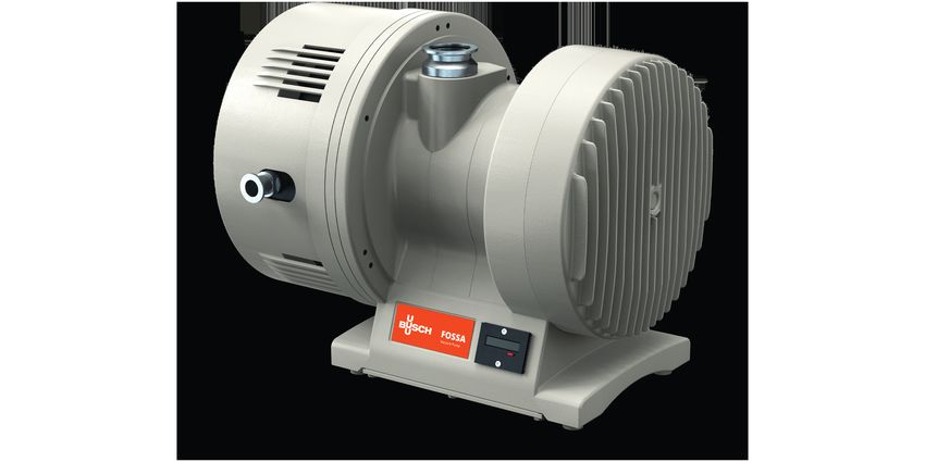
FOSSA
Scroll Vacuum Pumps
FO 0015 A
instruction manuals,
Get technical data,
service kits
Ateliers Busch S.A.
Zone industrielle, 2906 Chevenez
Switzerland
0870555373/-0001_de_en_fr / Original instructions / Modifications reserved 06/07/2021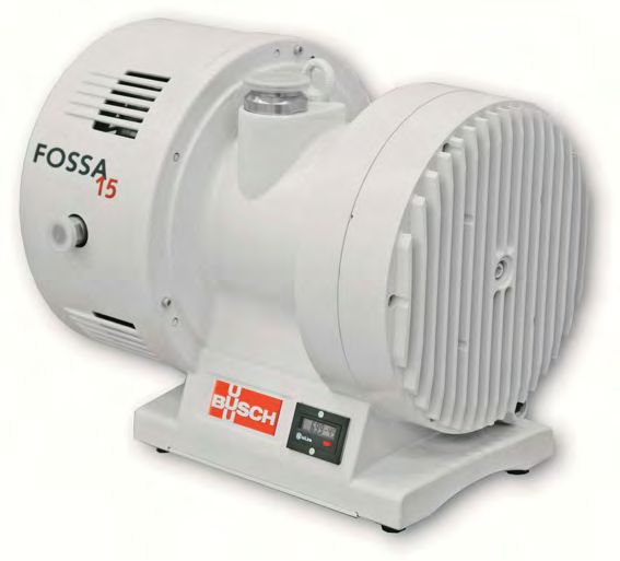
Inhaltsverzeichnis
Sicherheitshinweise 4
UK Declaration of Conformity. . . . . . . . . . . . . . . . . 32
33
33
34
35
35
35
35
36
36
Sicherheitshinweise 36
36
36
36
37
37
37
37
38
38
38
38
38
38
38
16 39
UK-Konformitätserklärung. . . . . . . . . . . . . . . . . . . 17 39
39
39
39
39
40
41
42
42
42
42
43
44
45
UE 46
Déclaration UK de conformité. . . . . . . . . . . . . . . . . 47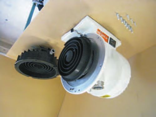
Deutsch

Einleitung
Herzlichen Glückwunsch zu der Vakuumpumpe von Busch. Mit auf-
merksamer Beobachtung der Bedürfnisse der Anwender, mit Innova-
tion und beständiger Weiterentwicklung liefert Busch moderne
Vakuum- und Drucklösungen weltweit.
Diese Betriebsanleitung enthält Information zu
–   Produktbeschreibung,
–   Sicherheit,
–   Transport,
–   Lagerung,
–   Installation und Inbetriebnahme,
–   Wartung,
–   Instandhaltung und
–   Störungsbehebung
der Vakuumpumpe.
„Umgang“ mit der Vakuumpumpe im Sinne dieser Betriebsanleitung
sind der Transport, die Lagerung, die Installation, die Inbetriebnahme,
die Einflussnahme auf Betriebsbedingungen, die Wartung, die Störung-
sbehebung und die Instandhaltung der Vakuumpumpe.
 Vor dem Umgang mit der Vakuumpumpe ist diese Betriebsanleitung
zu lesen und zu verstehen. Bei Unklarheiten wenden Sie sich bitte an
die zuständige Busch-Vertretung!
 Diese Betriebsanleitung und ggf. weitere zugehörige Betriebsanlei-
tungen am Einsatzort bereithalten.

FO 0015 A                                                                      Deutsch
                                                                          Seite / Page 3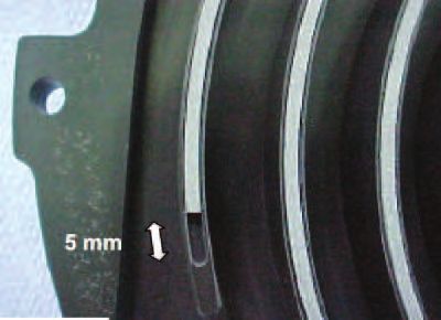
8
                 2

                 3

                 1                                                                                                     1   Haube
                                                                                                                       2   Ringschraube
                                                                                                                       3   Einlass
                                                                                                                       4   Auslass
                                                                                                                       5   Klemmenkasten mit
                                                                                                                           Betriebsstundenzähler
                 4                                                                                                     6   Schwingmetallpuffer
                                                                                                                           Befestigung
                                                                                                                       7   Buchse oder Stecker
                                                                                                                           (Option)
                                                                                                                       8   Verschlussschraube

                 5

                 7

                 6

                   Verdichtungsvorgang

        a   b            c   d            e

                Pos. 1           Pos. 2            Pos. 3              Pos. 4                Pos. 5
                                                                                                                      a    Feststehende Spirale
                                                                                                                      b    Bewegliche Spirale
                                                                                                                      c    Gaseinlass
                                                                                                                      d    Gasauslass
                                                                                                                      e    Gaseinschluss

Diese Betriebsanleitung hat Gültigkeit für folgende Pumpen:
                                                                                          ACHTUNG
–   FO 0015 A
                                                                                 Flüssigkeiten und Feststoffe dürfen nicht in die Pumpe gelangen.
              ACHTUNG
                                                                                 Nicht geeignet für aggressive Gase und für zündfähige Gemische.
 Diese Betriebsanleitung ist vor der Installation und Inbetriebnahme
 der Vakuumpumpe unbedingt zu lesen und zu befolgen.                             Im Zweifelsfall unbedingt Rücksprache mit Ihrer örtlichen
                                                                                 Busch-Vertretung halten.
Hersteller:
Ateliers Busch S.A.                                                             Sicherheitshinweise
Zone industrielle                                                               In dieser Installations- und Betriebsanleitung werden jeweils vor den
CH 2906 Chevenez                                                                betreffenden Handlungsschritten Sicherheitshinweise genannt. Diese
Schweiz
                                                                                Hinweise sind unbedingt zu beachten.
Telefon: +41 (0)32 476 02 00
Fax: +41 (0)32 476 03 99

Sicherheit
Diese Vakuumpumpen sind nach dem Stand der Technik und den
anerkannten sicherheitstechnischen Regeln gebaut. Dennoch können
bei unsachgemässer Installation oder nicht bestimmungsgemässem Be-
trieb Gefahren und Schäden entstehen.

Sicherheit                                                                                                                                   FO 0015 A

Seite / Page 4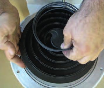
Ein Ansaugsieb (10) schützt die Pumpe vor dem Ansaugen von grösse-
Anwendung                                                                  ren Partikeln.
Diese Vakuumpumpen sind für den Einsatz im Feinvakuumbereich kon-
zipiert. Sie können für das Fördern von Gasen und Gasgemischen ver-
wendet werden.                                                                                                                             12
Andere Medien dürfen nicht gefördert werden. Wenden Sie sich im
                                                                                                                                           11
Zweifelsfall an Ihre örtliche Busch-Vertretung.                                      13                                                    10
Die zulässige Höchsttemperatur des angesaugten Gases hängt vom
Ansaugdruck und von der Art der angesaugten Gase ab. Je niedriger
der Ansaugdruck (Pa), desto höher darf die Temperatur des angesaug-
ten Gases (TGas) sein. Man kann für Luft die folgenden Hinweise in
Betracht ziehen:
–   Pa < 50 mbar, TGas < 200°C
–   Pa > 50 mbar, TGas < 70°C
Die Vakuumpumpe ist für den Einsatz in einer potentiell nicht explo-
sionsgefährlicher Umgebung vorgesehen.
                                                                                     13
Max. zulässige Anzahl von Starts pro Stunde: 6.

Funktionsprinzip und                                                       10 Sieb
Arbeitsweise                                                               11 O-Ring
Die Spiral-Vakuumpumpe Fossa besteht im wesentlichen aus einer fest-
                                                                           12 Sauganschluss
stehenden und einer beweglichen Spirale. Beide Spiralen greifen
während der Drehbewegung ineinander und bilden sichelförmige Gas-          13 Kühlluftaustritt
räume. Dabei wird durch die exzentrisch kreisende Spirale das Gas kon-
tinuierlich verdichtet und zum Zentrum der Spiralen gefördert, wo sich
                                                                           Die Vakuumpumpe ist mit einem Betriebsstundenzähler ausgerüstet.
der Gasaustritt befindet.
                                                                           Eine Gasballasteinrichtung ist zusammen mit der Pumpe unmontiert,
Fossa Spiral-Vakuumpumpen enthalten keinerlei Schmier-, Dicht- oder        geliefert.
Getriebeöl. Die Kugellager mit Dauerschmierung befinden sich nicht im
Pumpraum und sind dementsprechend nicht den angesaugten Gasen
ausgesetzt.                                                                Transport und Verpackung
                                                                                                 ACHTUNG

                                                                            Vor dem Anheben der Vakuumpumpe muss ihr Gewicht überprüft
                                                                            werden (siehe "Technische Daten").

                                                                            Die hierfür geeignete Hebevorrichtung versehen.

 Massblatt
 FO 0015 A

                                                      Eintrittsanschluss

                                 Austrittsanschluss
                                                                                                                  Betriebsstundenzähler

                                                                                                                  Kabelverschraubung
                                                                                                                  M20x1.5

FO 0015 A                                                                                             Funktionsprinzip und Arbeitsweise
                                                                                                                                     Seite / Page 5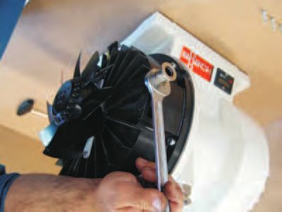
Die Vakuumpumpen werden im Werk auf Funktion überprüft und                –    Um kondensierbare Dämpfe ansaugen zu können, sollte das Gas-
fachgerecht verpackt. Achten Sie bei der Annahme der Pumpe auf                 ballastventil offen sein. So wird die Kondensation von Dämpfen in-
Transportschäden.                                                              nerhalb der Vakuumpumpe vermieden, indem die angesaugten
Die Saug- und Abluftanschlüsse sind mit Stopfen verschlossen, damit            Dämpfe verdünnt werden, bevor sie aus der Vakuumpumpe eva-
während des Transportes kein Schmutz in die Pumpe gelangen kann.               kuiert werden können.
Diese Stopfen müssen vor Inbetriebnahme der Pumpe entfernt werden.        Das Gasballastventil beinhaltet einen Filter, der pro Jahr mindestens
Die Pumpe kann an der Ringschraube (2) angehoben werden.                  einmal gereinigt werden sollte, oder alle zwei Jahre ausgewechselt wer-
                                                                          den sollte.
Das Verpackungsmaterial ist nach den geltenden Bestimmungen zu
entsorgen bzw. wiederzuverwenden.                                         Die folgenden Schritte sollten durchgeführt werden, um ein Gas-
                                                                          ballstventil zu installieren:
Diese Betriebsanleitung ist Bestandteil der Lieferung.
                                                                          •   Die Vakuumpumpe anhalten
Inbetriebnahme                                                            •   Mit einem 8 mm Inbusschlüssel den Blindstopfen entfernen
Die Einhaltung der Reihenfolge der hier beschriebenen Arbeitsschritte
ist für eine sicherheitsgerechte und funktionssichere Inbetriebnahme      •   Das Zubehör einschrauben und handfest anziehen
unbedingt erforderlich.
                                                                          •   Das Gasballastventil kann mit einem 8 mm Inbusschlüssel geéffnet
Die Inbetriebnahme darf nur von geschultem Fachpersonal durch-                oder geschlossen werden
geführt werden.

Aufstellung
Die Vakuumpumpe ist mit schwingmetallpuffer (mit M6-Gewinde für
die Befestigung) montiert.
Folgende Umgebungsbedingungen müssen gegeben sein:
–     Umgebungstemperatur: 5 - 40 °C
–     Umgebungsdruck: Atmosphäre
Um ein Überhitzen der Pumpe zu vermeiden, ist stets auf genügend
Frischluftzufuhr zu achten.
Die Pumpe wird mit senkrechter Anordnung der Ansaug- und
waagrechter Anordnung der Austrittanschlüsse geliefert.

Ansaug- und Austrittanschlüsse
Der Anschluss an den Saugflansch kann über einen vakuumdichten,
                                                                          Kühlluftrichtung prüfen
flexiblen Schlauch oder durch Rohrleitungen erfolgen.                     •   Zur Prüfung, ob Luft herausgeblasen wird (vom Axiallüfter), kann
Verengungen in den Anschlussleitungen sind zu vermeiden, da sonst             die Handfläche auf einen der Kühlluftaustritte der Haube gelegt
die Saugleistung vermindert wird. Die Nennweite der Anschlussleitun-          werden (13).
gen muss mindestens dem Querschnitt des Saugflansches der Pumpe
entsprechen.                                                              •   Bei zu kleinem, oder überhaupt keinem Luftstrom, muss die Verka-
                                                                              belung des Axiallüftermotors kontrolliert werden.
Sicherstellen, dass sich keine Fremdkörper oder Flüssigkeiten in der
Ansaugleitung befinden. Diese können die Vakuumpumpe zerstören.           •   Die Kühlluft-Öffnungen müssen frei bleiben.
Die Abgasleitung immer so anbauen, dass kein Kondensat in die
Pumpe gelangen kann (Gefälle, Siphon).
Um den Rücklauf des Prozessgases in den Prozess zu vermeiden, emp-
                                                                          Elektroanschluss
fehlen wir Ihnen, an der Ansaugseite eine Rückschlagklappe oder ein
Absperrorgan einzubauen.                                                                      WARNUNG

                                                                           Die Elektroinstallation darf nur von einem Fachmann durchgeführt
    Verschraubung     Sauganschluss        Abluftanschluss                 werden. Bestimmungen nach EMV-Richtlinie 2014/30/EU sowie
                      KF-DIN 28403         KF-DIN 28403                    die entsprechenden EN-Normen sind ebenso einzuhalten wie VDE/
                                                                           EVU-Richtlinien bzw. örtliche oder nationale Vorschriften. Der Be-
    FO 0015 A         DN 40                DN 16
                                                                           treiber der Vakuumpumpe hat dem Hersteller mitzuteilen, wenn
                                                                           elektrische oder elektromagnetische Störungen aus seinem Netz zu
                                                                           erwarten sind.
Zubehör                                                                   •   Die Spannungs- und Frequenzangaben auf dem Motorentypen-
Gas ballast                                                                   schild müssen mit der Netzspannung übereinstimmen.
–     Gas ballast, Busch Artikel-Nr: 0540 559 847                         •   Der Antriebsmotor ist nach VDE 0113 gegen Überlastung abzusi-
Eine Gasballasteinrichtung ist zusammen mit der Pumpe unmontiert,             chern.
geliefert.
                                                                          •   Zum Anschluss des Motors müssen folgende Schritte beachten wer-
Ein Gasballastventil kann an die Vakumpumpe montiert werden, um               den:
die Leistung der Pumpe zu optimisieren:
–     Um den bestmöglichen Enddruck erreichen zu können, sollte das       •   Den Deckel des Klemmenkastens entfernen
      Gasballastventil geschlossen bleiben. Falls die Vakuumpumpe be-          ¨ Die Pumpe auf die Seite legen
      nutzt wurde, um kondensierbare Dämpfe anzusaugen, kann es
      nötig sein, die Vakuumpumpe mindestens eine Stunde lang mit of-          ¨ Die Spannung und Frequenz der Stromversorgung kontrollieren
      fenem Gasballastventil laufen zu lassen, bevor dieses wieder ges-
      chlossen werden kann und die Vakuumpumpe wieder ihren besten             ¨ Die Elektrokabel durch der Kabelverschraubung durchziehen
      Enddruck erreichen kann.
Inbetriebnahme                                                                                                                        FO 0015 A

Seite / Page 6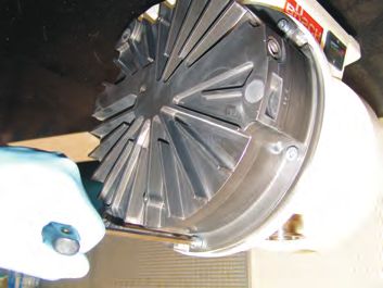
¨ Die Kabel gemäss ihrer vorliegenden Spannungsart anschliessen      Klemmenkasten-Anschlüsse Dreieckschaltung
    ¨ Den Deckel des Klemmenkastens schliessen                           190-220 V 50 Hz, 200-240 V 60 Hz

                                                                                         F4 F2

                                                                                                        V2       U2

                                                                                                        W1       V1

                                                                                    Dreickschaltung           Fan 1 (F1): weiss
•   Zur Prüfung der Drehrichtung (bei Drehstrommotor) Pumpe kurz                    Niedrige Spannung
                                                                                    190-220 V 50 Hz
                                                                                                              Fan 2 (F2): braun
                                                                                                              Fan 3 (F3): grün
    ein- und ausschalten. Zur Kontrolle, ob Luft angesaugt wird, kann
                                                                                    200-240 V 60 Hz           Fan 4 (F4): gelb
    die Handfläche auf den Ansaugflansch gelegt werden. Eine andere
    Möglichkeit besteht darin, die Drehrichtung des Motors mit der
    angegebenen Pfeilrichtung zu vergleichen. Von der Motorenseite
    ausgesehen ist die Drehrichtung nach rechts, im Uhrzeigersinn, die
    Verschlussschraube (8) entfernen.

    Bei falscher Drehrichtung, bei Drehstrom:                            Einphasige Verbindung
    ¨ Zwei der drei Phasen umpolen                                       Klemmenkasten-Anschlüsse 200-240 V
                                                                         50/ 60 Hz
Drehstrom Verbindung
Klemmenkasten-Anschlüsse Sternschaltung
380-415 V 50 Hz, 380-480 V 60 Hz
(Werkseinstellung)

                   F4 F2

                                 V2      U2

                                                                              Fan 1: weiss                   zur umgekehrten Drehrichtung
                                                                              Fan 2: braun                   => Z1-Z2 umkehren
                                                                              Fan 3: grün
                                                                              Fan 4: gelb
                                 W1      V1

               Sternschaltung           Fan 1 (F1): weiss
               Hohe Spannung            Fan 2 (F2): braun
               380-415 V 50 Hz          Fan 3 (F3): grün
               380-480 V 60 Hz          Fan 4 (F4): gelb

FO 0015 A                                                                                                                Elektroanschluss
                                                                                                                            Seite / Page 7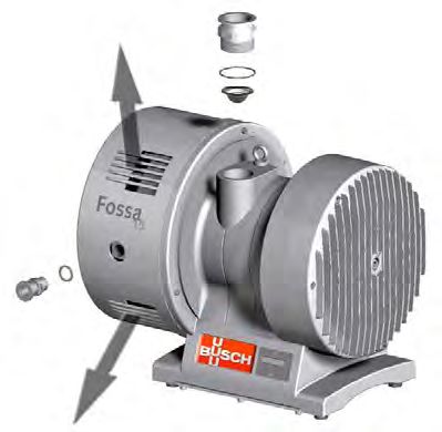
Klemmenkasten-Anschlüsse 110-115 V
50/ 60 Hz                                                                         ACHTUNG

                                                                         Die Vakuumpumpe darf nur von entsprechend geschultem Personal
                                                                         zerlegt werden. Vor dem Zerlegen muss der Betreiber der Vakuum-
                                                                         pumpe das Formular "Declaration of Contamination of vacuum
                                                                         Equipment and Components" ausfüllen, in dem auf jegliche Gefa-
                                                                         hren, die von der Vakuumpumpe ausgehen könnten, hingewiesen
                                                                         wird, sowie die entsprechenden Sicherheitsvorkehrungen getroffen
                                                                         werden. Ohne dieses vollständig ausgefülte Formular, welches von
                                                                         einem Verantwortlichen unterschrieben worden sein musss, darf die
                                                                         Vakuumpumpe nicht zerlegt werden.
                                                                         Vor sämtlichen Wartungsarbeiten muss die Vakuumpumpe vom
                                                                         Stromnetz genommen werden und gegen versehentliches Anlaufen
                                                                         geschützt werden.

                                                                        Servicetabelle
                                                                         Servicetabelle        Wartungsarbeit        Zeitabstand
     Fan 1: weiss                 zur umgekehrten Drehrichtung
     Fan 2: braun                 => Z1-Z2 umkehren                      Sieb                  Reinigung             je nach Anwendung
     Fan 3: grün
     Fan 4: gelb                                                         Gasballastventil      Reinigung             nach 8000 h,
                                                                         (Option)                                    je nach Anwendung

                                                                         Gasballastventil      Ersetzen              alle 2 Jahren,
                                                                         (Option)                                    je nach Anwendung

                                                                         Kopfdichtung          Ersetzen              alle 8000 h, je nach
Betriebshinweise                                                                                                     Anwendung
Diese Vakuumpumpen sind für das Fördern von sauberen und trocke-         Kugellager ersetzen   Ersetzen              alle 20000 Betriebs-
nen Gasen bestimmt, die weder aggressiv noch giftig sind. Nicht geei-    Kompletter Service    Nur durch Busch       stunden oder alle 4
gnet für zündfähige Gemische.                                                                  Kundendienst          Jahren
Andere Medien dürfen nicht gefördert werden. Wenden Sie sich im
Zweifelsfall an Ihre örtliche Busch-Vertretung.
                                                                        Die Wartungsintervalle sind sehr stark abhängig von den individuellen
                                                                        Betriebsbedingungen wenn die Vakuumpumpe aggressive Gase (wie
          ACHTUNG                                                       Lösemittel, organische Substanzen, Fettsäure¼) ansaugt oder unter
                                                                        besonders schwere Bedingungen betrieben wird (fördernden Gas, höhe
 Flüssigkeiten und Feststoffe dürfen nicht in die Pumpe gelangen.       Temperaturen¼).

 Nicht geeignet für aggressive Gase und für zündfähige Gemische.

Vor dem Betreiben mit Prozessgas muss die Vakuumpumpe kurz bei
                                                                        Sicherheitshinweise
Atmosphärendruck (offener Saugflansch) betrieben werden, um even-
tuell bei der Inbetriebnahme eingedrungene Staubpartikel aus der                            ACHTUNG
Pumpe zu entfernen.
Diese Luftspülung sollte nach Stillstand weitergeführt werden.           Vor dem Zerlegen muss die FOSSA Vakuumpumpe vom Strom- und
                                                                         Vakuumkreislauf getrennt werden.
Max. zulässige Anzahl von Starts pro Stunde: 6.

Wartung
           WARNUNG

 Vor der Installation, dem Anlaufen der FOSSA, FO 0015 A und je-
 glicher Wartungsarbeiten an dieser Vakuumpumpe, muss die Be-
 triebsanleitung der FOSSA, FO 0015 A unbedingt gelesen und
 verstanden werden.
 Bei Unklarheiten, wenden Sie sich bitte an die zuständige
 Busch-Vertretung!

Betriebshinweise                                                                                                                   FO 0015 A

Seite / Page 8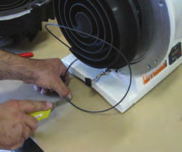
Reinigung des Siebes                                                  Reinigung des Gasballastventils
                                                                      (Zubehör)
             12                                                       Regelmässig überprüfen, ob das Gasballast ansaugt. Falls keine Luft
                                                                      oder Stickstoff angesaugt wird, muss das Gasballastventil abmontiert
             11                                                       und mit Druckluft ausgeblasen werden.
             10                                               9

9 Verschlussschraube
10 Sieb
11 O-Ring
12 Sauganschluss
                                                                      Auswechseln der Kopfdichtungen
                                                                      Verschleissteilsatz
                                                                      –   Verschleissteilsatz für die FOSSA, FO 0015 A: 0990 559 196
 Das Sieb ist regelmässig auf Verschmutzungen zu überprüfen. Eine
 Verschmutzung des Siebes kann das Saugvermögen absenken.             Werkzeug
 Gegebenenfalls muss das Sieb gereinigt werden.
                                                                      Folgende Werkzeuge werden für den Zusammenbau und die Demon-
•   Mit dem Werkzeug N° 0813 563 062, den Sauganschluss (12)          tage der FOSSA Vakuumpumpen benötigt:
    entfernen, denn das Sieb (10)

•   Sämtliche Verunreinigungen, die sich im Ansaugsieb angesammelt
    haben könnten, entfernen

•   Falls nötig, das Ansaugsieb mit einer Reinigungslösung säubern,
    welche mit den gepumpten Prozess-Substanzen verträglich ist

•   Das Ansaugsieb mit Druckluft durchblasen

•   Das Ansaugsieb wieder einsetzen, danach das Sauganschlussstück.
    Sicherstellen, das die Verbindung korrekt eingesetzt wurde und
    dicht ist

                                                                      Werkzeug

                                                                      Inbusschlüssel                       6 mm, idealerweise als T-Stück
                                                                                                                    ausgeführt

                                                                      Inbusschlüssel                                    4 mm

                                                                      Cutter-Messer                                       -

                                                                      Ring-Gabelschlüssel                              21 mm

                                                                      Für die Wartungsarbeiten an der Vakuumpumpe (Zerlegen, Zusam-
                                                                      menbau) sind keine Spezialwerkzeuge erforderlich.

FO 0015 A                                                                                                           Sicherheitshinweise
                                                                                                                              Seite / Page 9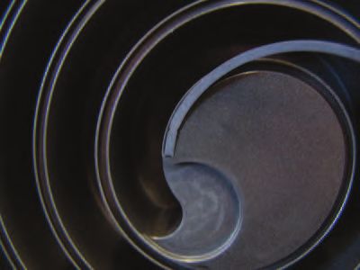
Zerlegen                                                                    •   Die feste Spirale auf einer flachen Arbeitsfläche ablegen
Die FOSSA Vakuumpumpe kann einfach zerlegt und wieder zusam-
mengebaut werden. Folgende Punkt müssen befolgt werden, damit
keine Schäden an Bauteilen entstehen und die Vakuumpumpe nach
dem Zusammenbau wieder einwandfrei funktionniert.

•   Die drei Schrauben der Schutzhaube abschrauben und die Schutz-
    haube abnehmen.

                                                                            •   Die alte Kopfdichtung mit einem spitzen Werkzeug, z.B. der Spitze
                                                                                des Cutter-Messers, am äussersten Rand am Spiralanfang anfangen,
                                                                                abzunehmen. Diesen Vorgang sowohl für die feste, als auch für die
                                                                                bewegliche Spirale durchführen.

•   Auf den Stecker drücken, um den Lüfteranschluss abzuschalten

 Beim Trennen, darauf achten, die Leitungen nicht zu reissen!

                                                                            •   Sicherstellen, dass sich keine Fremdkörper in der Nut der Spirale be-
                                                                                finden. Auch die Nut für die Kopfdichtung sollte überprüft werden.
                                                                                Alle Spiralen einschliesslich der Kopfdichtungsnut mit einem weichen
                                                                                und fusselfreien Tuch abwischen, welches in Alkohol getränkt
                                                                                wurde.

•   Die 6 Schrauben der festen Spirale abschrauben

                                                                            Neue Kopfdichtungen
•   Die feste Spirale vorsichtig entfernen, falls nötig, mit vorsichtigem   •   Mit dem Cutter-Messer nun zwei kleine Einkerbungen (jede etwa
    Hin- und Hebewegen der Spirale                                              0,3 mm tief) einschneiden. Diese Einkerbungen werden der Kopf-
                                                                                dichtung ermöglichen, sich am inneren Anfang der Spirale festsetz-
                                                                                ten zu können (Haltekrallen).

Sicherheitshinweise                                                                                                                         FO 0015 A

Seite / Page 10
• Die neue Dichtung in die Nut einlegen und einstellen, dabei von der • Nochmals überprüfen, dass sich keine Fremdkörper in der beiden
Mitte der Spirale aus anfangen. Ziel dieses Arbeitsschrittes ist, die Spiralen befinden.
Position der beiden Befestigungskrallen zu markieren.
• Die feste Spirale vorsichtig wieder einsetzen. Die sechs Schrauben
gleichmässig und regelmässig anziehen.
• In der Mitte der Spirale mit dem Einsetzen beginnen und dann die
Kopfdichtung weiter entlang der Nut einfädeln.
• Den Lüfteranschluss schalten
Beim Schalten, darauf achten, die Leitungen nicht zu reissen!
• Das Ende der Kopfdichtung soweit abschneiden, dass zwischen dem
Ende der Dichtung und dem Ende der Nut 5 mm übrig bleiben.
• Die Schutzhaube wieder einsetzen und mit den drei Schrauben fest-
machen.
Unter Fingerdruck sicherstellen, dass die Kopfdichtung richtig in
ihrer Nut sitzt und dass es keine Beule an den zwei Anschnitten
gibt
• Den gleichen Vorgang mit der anderen Spirale wiederholen
Zusammenbau
• Den mit Fomblin-Fett leichtgefetteten O-Ring auf der festen Spirale
auswechseln, dabei die Dichtfläche auf dem Pumpengehäuse
überprüfen.
FO 0015 A Sicherheitshinweise
Seite / Page 11Die Dichtung des Weitere Wartungsarbeiten
Rücksaugstopp-Ventils ersetzen Um den sicheren Betrieb der Pumpe zu gewährleisten, empfehlen wir,
mindestens alle 8000 Betriebsstunden einen Service von Busch
• Den Druckflansch mit Hilfe des 21 mm Schraubenschlüssels entfer- durchführen lassen.
nen: dieser Arbeitsschritt kann sowohl mit als auch ohne Entfernen
der Lüfterhaube durchgeführt werden. Dazu muss die Fossa Vakuumpumpe aus der Anlage des Betreibers
ausgebaut werden. Je nach Anwendungsfall muss die Pumpe zuvor mit
Stickstoff gespült oder gereinigt werden. Dabei sind alle für das ge-
fördete Medium relevanten Sicherheitsvorschriften einzuhalten.
Der Betreiber muss entweder beim Versand der Vakuumpumpe an die
örtliche Busch-Vertretung schriftlich bestätigen, dass die Vakuum-
pumpe nur mit unbedenklichen Substanzen in Berührung gekommen
ist.
Oder er muss eine Unbedenklichkeitsbescheinigung ausfüllen, in der
auf eventuelle Gefahren durch das geförderte Medium und auf die
geeigneten Schutzvorkehrungen hingewiesen werden muss.
Die Vakuumpumpe muss unbedingt vor dem Versand dekontaminiert
werden, und der Kontaminationszustand ist in einer Eklärung über die
Dekontaminierung der Vakuumpumpe zu dokumentieren ("Declaration
of Decontamination"), Formblatt bei www.buschvacuum.com herun-
O-Ring, der ersetzt werden soll terladbar.
• Den O-Ring am Abluftventil auswechseln
Informationen
Weitere Informationen senden wir Ihnen auf Anfrage gerne zu.
Verfügbar ist:
– Typenblatt Fossa FO
– Unbedenklichkeitsbescheinigung
• Die Einzelteile wieder in die feste Spirale einführen und vorsichtig
mit dem Schraubenschlüssel festziehen
VORSICHT
Die Abfallstoffe gemäss den geltenden Sicherheits- und Umwelt-
vorschriften entsorgen.
Besonders vorsichtig muss bei Bauteilen vorgegangen werden, die
mit gefährlichen Prozess-Substanzen in Berührung gekommen sind.
Einfahren
Falls die Stromkabel im Klemmenkasten entfernt worden sind, muss die
korrekte Drehrichtung der Vakuumpumpe ermittelt werden, indem
man die Vakuumpumpe mit geöffnetem Sauganschluss laufen lässt uns
sicherstellt, dass sie dann auch ansaugt.
Den Lüftergang kontrollieren.
Ein Helium-Lecktest kann durchgeführt werden, um die Leckrate zu
überprüfen.
Hersteller-Nennwert: 1x10⁻⁶mbar.l/s.
Informationen FO 0015 A
Seite / Page 12Störungsbehebung
Nr Fehler Ursache / Kontrolle Tätigkeit
1 Kein Vakuum · Motordrehrichtung falsch · Zwei Phasen des Elektroanschlusses umpolen
· Saugleitung verstopft · Saugleitung reinigen
· Saugleitung undicht · Saugleitung kontrollieren, ggf. austauschen
· Ansaugsieb verstopft · Sieb reinigen oder austauschen
2 Schlechter Enddruck · Vakuumsystem undicht · Vakuumsystem auf Dichtheit kontrollieren
· Kondensatbildung in der Pumpe · Pumpe mit geöffneter Saugleitung mit Luft
trockenfahren oder das Gasballastventil (Zubehör)
· Verschlissene Kopfdichtungen verwenden
· Kopfdichtungen auswechseln
3 Erhöhte Stromaufnahme · Gegendruck zu hoch · Auslassleitung kontrollieren
· Defekte Kugellager · Lager durch den Busch-Service austauschen
· Pumpe mit Prozessrückständen verstopft · Pumpe durch Busch-Service überprüfen lassen
4 Erwärmung der Pumpe · Frischluftzufuhr ungenügend · Frischluftzufuhr verbessern
· Pumpe mit Prozessrückständen verstopft · Pumpe durch Busch-Service überprüfen lassen
· Auslassleitung verstopft · Auslassleitung kontrollieren
· Motor defekt · Motor kontrollieren
· Umgebungstemperatur zu hoch · Umgebungstemperatur kontrollieren
5 Erhöhte Geräusche · Auslassleitung verstopft · Auslassleitung kontrollieren, ggf. reinigen
· Motordrehrichtung falsch · Zwei Phasen des Elektroanschlusses umpolen
· Pumpe mit Prozessrückständen verstopft · Pumpe durch Busch-Service überprüfen lassen
· Defekte Kugellager · Kugellager austauschen
6 Kondensation in der Pumpe · Kondensierbaren Dämpfe-Ansaugung zu hoch · Prozess kontrollieren
· Gasballastventil defekt (Zubehör) · Gasballastventil reinigen, ggf. austauschen
FO 0015 A Störungsbehebung
Seite / Page 13Explosionszeichnung Explosionszeichnung FO 0015 A Seite / Page 14
Technische Daten
 Technische Daten                                                                      FO 0015 A

                                                                               50 Hz                  60 Hz

                                                                    l/min      250                    300
                                                                      3
 Nennsaugvermögen                                                   m /h        15                     18
                                                                     cfm        8,8                   10,6

 Enddruck                                                         hPa (mbar)           £ 2,5 x 10⁻²

                                                                     hPa
 Enddruck mit Gasballastventil    (Option)                                             £ 3,5 x 10⁻²
                                                                    (mbar)

 Leckrate                                                          mbar. l/s            < 1 x 10⁻⁶

                                                                     kW
 Motornennleistung                                                                         0,4
                                                                      hp

 Motornenndrehzahl                                                  min-1      1480                   1780

                                                                                  D 3 x 190-220/
                                                                                Y 3 x 380-415 (50 Hz)
                                                                      V           D 3 x 200-240/
                                                                                Y 3 x 380-480 (60 Hz)

 Motorspannung                                                        V                   oder

                                                                                       1 x 200-240
                                                                      V                   oder

                                                                                       1 x 100-115

                                  Wechselstrom     100-115 V          A                  T 12,5
 Empfohlene Sicherungsauslegung
                                  Wechselstrom     200-240 V          A                    T8

                                  Drehstrom-Motor mit Kabelverschraubung                  IP 44
 IP Code                          Wechselstrom-Motor mit Kabelbuchse                      IP 44
                                  Wechselstrom-Motor mit Schalter (Option)                IP 40

 Schalldruckpegel                 EN ISO 2151    dB(A)                         < 57                   < 59

 Gewicht ca.                                                          kg                   48

FO 0015 A                                                                                 Technische Daten
                                                                                             Seite / Page 15
EU-Konformitätserklärung
Die vorliegende EU-Konformitätserklärung und die auf dem Typenschild angebrachte CE-Kennzeichnung gelten
für die Maschine im Rahmen des Lieferumfangs von Busch. Die alleinige Verantwortung für die Ausstellung dieser
Konformitätserklärung trägt der Hersteller.
Wird die Maschine in eine übergeordnete Maschinenanlage integriert, muss der Hersteller dieser Anlage (ggf. das
die Anlage betreibende Unternehmen) die übergeordnete Maschine bzw. Anlage, eine Konformitätserklärung aus-
stellen und die CE-Kennzeichnung anbringen.
Hersteller Ateliers Busch S.A.
Zone Industrielle
CH-2906 Chevenez
Erklärung für die Maschine(n) vom Typ: FOSSA FO 0015 A
alle relevanten Vorschriften der Europäischen Richtlinien erfüllen:
– „Maschinenrichtlinie“ 2006/42/EG
– „Richtlinie über elektromagnetische Verträglichkeit“ 2014/30/EU
– „RoHS-Richtlinie“ 2011/65/EU, Beschränkung der Verwendung bestimmter gefährlicher Stoffe in Elektro- und
Elektronikgeräten (einschließlich aller im Zusammenhang anwendbaren Änderungen)
und erfüllen die in der Folge genannte Normen, die verwendet wurden, um diesen Vorschriften nachzukommen:
Norm Name der Norm
EN ISO 12100:2010 Sicherheit von Maschinen – allgemeine Gestaltungsleitsätze
EN ISO 13857:2019 Sicherheit von Maschinen – Sicherheitsabstände gegen das Erreichen von Ge-
fährdungsbereichen mit den oberen und unteren Gliedmaßen
EN 1012-1:2010 Kompressoren und Vakuumpumpen – Sicherheitsanforderungen – Teil 1 und
EN 1012-2:1996 + A1:2009 Teil 2
EN ISO 2151 : 2008 Akustik – Geräuschmessnorm für Kompressoren und Vakuumpumpen – Ver-
fahren der Genauigkeitsklasse 2
EN 60204-1 : 2018 Sicherheit von Maschinen – Elektrische Ausrüstung von Maschinen – Teil 1:
Allgemeine Anforderungen
EN IEC 61000-6-2:2019 Elektromagnetische Verträglichkeit (EMV) – Fachgrundnormen. Störfestigkeit
für Industriebereiche
EN IEC 61000-6-4:2019 Elektromagnetische Verträglichkeit (EMV) – Fachgrundnormen. Störaussen-
dung für Industriebereiche
EN ISO 13849-1 : 2015 (1) Sicherheit von Maschinen – Sicherheitsbezogene Teile von Steuerungen – Teil
1: Allgemeine Gestaltungsleitsätze
(1)
Falls Steuerungen integriert sind.
Zur Erstellung der technischen Unterlagen befugte juristische Person und Busch Dienste GmbH
autorisierter Vertreter in der EU (wenn der Hersteller nicht in der EU an- Schauinslandstr. 1
sässig ist): DE-79689 Maulburg
Chevenez, 14.05.2021
Christian Hoffmann, General Direcktor
16UK-Konformitätserklärung
Die vorliegende Konformitätserklärung und die auf dem Typenschild angebrachte UKCA-Kennzeichnung gelten für
die Maschine im Rahmen des Lieferumfangs von Busch. Die alleinige Verantwortung für die Ausstellung dieser
Konformitätserklärung trägt der Hersteller.
Wird die Maschine in eine übergeordnete Maschinenanlage integriert, muss der Hersteller dieser Anlage (ggf. das
die Anlage betreibende Unternehmen) der übergeordneten Maschine bzw. Anlage, eine Konformitätserklärung
ausstellen und die UKCA-Kennzeichnung anbringen.
Hersteller Ateliers Busch S.A.
Zone Industrielle
CH-2906 Chevenez
Erklärung für die Maschine(n) vom Typ: FOSSA FO 0015 A
Erfüllt/Erfüllen alle relevanten Bestimmungen aus britischen Richtlinien:
– Verordnung über die Lieferung von Maschinen (Sicherheit) 2008
– Vorschriften zur elektromagnetischen Verträglichkeit 2016
– Beschränkung der Verwendung bestimmter gefährlicher Stoffe in Elektro- und Elektronikgeräten Regulierung
2012
und entspricht/entsprechen den folgenden bezeichneten Normen, die zur Erfüllung dieser Bestimmungen verwen-
det wurden:
Norm Name der Norm
BS EN ISO 12100 : 2010 Sicherheit von Maschinen. Grundlegende Konzepte, allgemeine Gestaltungslei-
tsätze. Risikobeurteilung und Risikoreduzierung
BS EN ISO 13857 : 2019 Sicherheit von Maschinen – Sicherheitsabstände gegen das Erreichen von Ge-
fährdungsbereichen mit den oberen und unteren Gliedmaßen.
BS EN 1012-1 : 2010 Kompressoren und Vakuumpumpen. Sicherheitsanforderungen. Luftverdichter
BS EN 1012-2 : 1996 + A1 : 2009 und Vakuumpumpen.
BS EN ISO 2151 : 2008 Akustik – Geräuschmessnorm für Kompressoren und Vakuumpumpen – Ver-
fahren der Genauigkeitsklasse 2
BS EN 60204-1 : 2018 Sicherheit von Maschinen. Elektrische Ausrüstung von Maschinen. Allgemeine
Anforderungen.
BS EN IEC 61000-6-2 : 2019 Elektromagnetische Verträglichkeit (EMV) – Fachgrundnormen. Störfestigkeits-
norm für industrielle Umgebungen.
BS EN IEC 61000-6-4 : 2019 Elektromagnetische Verträglichkeit (EMV) – Fachgrundnormen. Emissionsnorm
für industrielle Umgebungen.
BS EN 13849-1 : 2015 (1) Sicherheit von Maschinen. Sicherheitsbezogene Teile von Steuerungen. Allge-
meine Gestaltungsleitsätze
(1)
Falls Steuerungen integriert sind.
Juristische Person mit der Befugnis, die technischen Unterlagen Busch (UK) Ltd
zu erstellen, und Importeur im Vereinigten Königreich 30 Hortonwood
(wenn der Hersteller nicht im Vereinigten Königreich ansässig ist): Telford - UK
Chevenez, 14.05.2021
Christian Hoffmann, Generaldirektor
17English
Introduction
Congratulations on your purchase of the Busch vacuum pump. With wat-
chful observation of the field’s requirements, innovation and steady deve-
lopment Busch delivers modern vacuum and pressure solutions
worldwide.
These operating instructions contain information for
– product description,
– security,
– transport,
– storage,
– installation and commissioning
– maintenance,
– overhaul,
– troubleshooting
of the vacuum pump.
For the purpose of these instructions, “handling” the vacuum system
means the transport, storage, installation, commissioning, influence on
operating conditions, maintenance, troubleshooting and overhaul of the
vacuum system.
Prior to handling the vacuum system, these operating instructions shall
be read and understood. If anything remains to be clarified please
contact your Busch representative!
Keep these operating instructions and, if applicable, other pertinent
operating instructions available on site.
FO 0015 A English
Seite / Page 188
2
3
1 1 Cover
2 Eye bolt
3 Inlet flange
4 Outlet flange
5 Electrical box with operating
hours counter
4 6 Rubber feet
7 Cable gland or switch
(option)
8 Plug screw
5
7
6
Compression cycle
a b c d e
Pos. 1 Pos. 2 Pos. 3 Pos. 4 Pos. 5
a Fixed scroll
b Rotating scroll
c Gas inlet
d Gas outlet
e Gas pocket
These installation and operating instructions are valid for the following
pumps: CAUTION
– FO 0015 A Liquid and solid particles must not enter the pump.
Not to be used to evacuate aggressive gases or ignitable gas mixtu-
CAUTION
res.
It is mandatory that these operating instructions are read and un-
In case of doubt consult your local Busch Agency.
derstood prior to the vacuum pump installation and start-up.
Manufacturer: Safety advice
Ateliers Busch S.A. In these operating instructions safety measures are stated before each
Zone industrielle step. It is imperative that these safety precautions are observed.
CH 2906 Chevenez
Switzerland
Telefon: +41 (0)32 476 02 00
Fax: +41 (0)32 476 03 99
Safety
These vacuum pumps have been manufactured according to the tech-
nical standards and safety regulations. If not installed properly or not
used as directed, dangerous situations or damage might occur.
FO 0015 A Safety
Seite / Page 19A mesh (10) is installed at the pump’s inlet to prevent bigger particles
Application from entering into the pump.
These vacuum pumps are designed for use in the fields of fine vacuum.
They can be used to evacuate gas or gas mixtures.
Other agents should not be transported. In case of doubt, please
contact your local Busch-Agency 12
The maximum admissible temperature of drawn gas depends on the
inlet pressure and the nature of the gases. The lower the inlet pressure 11
13 10
(Pa), the higher can be the drawn gas temperature (TGas). We can
consider as air the following indications:
– Pa < 50 mbar, TGas < 200°C
– Pa > 50 mbar, TGas < 70°C
The vacuum pump is designed for use in an environment which is
non-explosive.
Max. permissible number of startings per hour: 6.
Principle of operation
Fossa scroll vacuum pumps mainly consist of a fixed scroll and a rota-
ting scroll when rotating both scrolls form crescent shaped gas pro- 13
ducts. By the eccentrically rotating scroll, the gas is compressed
continuously and conveyed to the center of the spirals and therefore to
the gas outlet.
Fossa scroll vacuum pumps contain neither lubricating, sealing nor gear
oil in the pumping chamber. The greased ball bearings are not in the 10 Mesh
pumping chamber, therefore not in direct contact with the pumped
11 O-ring
gas.
12 Inlet connection
13 Cooling air openings
The pump is equipped with an operating hours counter. A gas ballast
accessory is delivered unassembled with the pump.
Dimensional drawing 179 346
FO 0015 A
55 205
Inlet connection
DN40 ISO-KF
Outlet connection
DN16 ISO-KF Hours counter
369
347
207
Cable gland
M20x1.5
4xM6
180
260 36
338
450
Principle of operation FO 0015 A
Seite / Page 20may be necessary to run it for at least an hour with an open gas
Transport and packing ballast, before closing it again and obtaining the best end pressure.
– In order to pump condensable vapours, the gas ballast should be
CAUTION open. It will prevent the condensation of vapours in the pump
through dilution of the pumped gas and clearing the condensates
Please check out the weight of the vacuum pump before lifting it up out of the pump.
(see "Technical Data"). The gas ballast includes a filter, and this needs to be cleaned annually
or exchanged every 2 years.
Use adequate lifting gear for this.
The following steps must be undertaken to install the gas ballast :
The vacuum pumps pass a rigorous test in the factory and are packed
carefully to avoid transport damage. Please check packing on delivery • Stop the pump
for transport damage.
• Remove the plug with a 8mm Allen key
The inlet and outlet ports are sealed with plugs so that no dust can pe-
netrate during transport. The plugs must be removed before starting • Screw in and tighten the accessory by hand the accessory
the vacuum pump.
The pump can be lifted from the packing using the eye bolt (2).
• The gas ballast can be opened or closed with an 8mm Allen key.
Packing materials should be disposed of according to environmental
regulations.
These operating instructions are part of the consignment.
Start-up
It is essential to observe the following instructions step by step to en-
sure a safe start-up.
Start-up may only be carried out by trained specialists.
Setting-up
The vacuum pump is mounted with rubber foots (with M6-threads for
fixation).
The following operating environment must be observed:
– Ambient temperature: 5 - 40 °C
– Ambient pressure = Atmosphere Cooling air direction check
In order to avoid overheating of the pump, an undisturbed fresh • Put the palm of your hand on the cooling air openings (13) of the
airflow to the pump is necessary. cover in order to check if air is put out from the fan.
The vacuum pump is delivered with inlet connection in vertical position
and oulet connection in horizontal position.
• In case of too low or none cooling air supply, check the electrical
connection of the fan motor.
Inlet and outlet connections • The cooling air opennings must be released.
The inlet flange can be connected with a vacuumtight flexible hose or
pipe.
Electrical connection
Restriction of the pipes must be avoided in order not to decrease the
displacement of the pump.The nominal diameter of the pipes has to be
at least the same as the diameter of the vacuum pump’s inlet flange. WARNING
No foreign particles or liquids must enter the inlet line, as they could Electrical installation may only be carried out by a specialist. Regu-
damage the vacuum pump. Always connect the exhaust pipe in a man- lations following EMV Directive 2014/30/EU, and the appropriate
ner, so that no condensate can enter the pump (slope, siphon). EN Standards have to be applied as well as VDE/ EVU regulations
In order to avoid process gases flowing back into the process, we re- and local or national regulations. The operator of the vacuum
commend you insert a non-return valve or a shut-off device which pump must inform the manufacturer, if electric or electromagnetic
must be installed at the inlet flange. interference from his mains is to be expected.
• Voltage and frequency on the nameplate of the motor must match
Connection Inlet connection Outlet connection the supply voltage.
KF-DIN 28403 KF-DIN 28403
• The drive motor must be protected against overloads according to
FO 0015 A DN 40 DN 16 VDE 0113.
• The following steps must be considered when connecting the motor
to the mains:
Accessory ¨ Lay down the pump onto its side
Gas ballast ¨ Remove cover of the terminal box
– Gas ballast, Busch Art. N°: 0540 559 847
¨ Check supply voltage and frequency
A gas ballast accessory is delivered unassembled with the pump.
¨ Pass the electric cable through the cable gland
A gas ballast can be installed on the pump to optimise the performance
of the pump : ¨ Connect phase and earthwires, appropriate to the voltage
– To achieve the best possible end pressure, the gas ballast should be ¨ Close the terminal box cover
closed. If the pump has been used to draw condensable vapours, it
FO 0015 A Transport and packing
Seite / Page 21Terminal box connection Delta coupling
190-220 V 50 Hz, 200-240 V 60 Hz
F4 F2
V2 U2
• To check the pump’s direction of rotation (for three-phase motor), W1 V1
switch on the pump for a few seconds. Verify that there is vacuum
by putting the palm of your hand on the inlet flange. Another possi-
bility is to compare the direction of rotation of the motor with the
direction indicated by the arrow. Looking at the motor, remove the Delta coupling Fan 1 (F1): white
plug screw (8). Low voltage Fan 2 (F2): brown
190-220 V 50 Hz Fan 3 (F3): green
In case of wrong direction of rotation in three-phase current opera- 200-240 V 60 Hz Fan 4 (F4): yellow
tion:
¨ Reverse polarity of two of the three electrical phases.
Three-phase connection Single phase connection
Terminal box connection Star coupling Terminal box connection 200-240 V
380-415 V 50 Hz, 380-480 V 60 Hz (Factory 50/ 60 Hz
default setting)
F4 F2
V2 U2
W1 V1
Fan 1: white To reverse rotation
Fan 2: brown => reverse Z1-Z2
Fan 3: green
Star coupling Fan 1 (F1): white Fan 4: yellow
High voltage Fan 2 (F2): brown
380-415 V 50 Hz Fan 3 (F3): green
380-480 V 60 Hz Fan 4 (F4): yellow
Electrical connection FO 0015 A
Seite / Page 22Terminal box connection 110-115 V Service schedule
50/ 60 Hz
Service schedule Service job Interval
Mesh Cleaning depending on the
applications
Gas ballast valve (option) Cleaning 8000 h, or as required
depending on the
applications
Gas ballast valve (option) Replacing Every 2 years, or as
required
depending on the
applications
Tip seal Replacing 8000 h, or as required
depending on the
applications
Bearings replacement Replacement Every 20000 hours of
Complete service Only by Busch main- operation or every 4
tenance service years
engineer
Fan 1: white To reverse rotation
Fan 2: brown => reverse Z1-Z2 The frequency of maintenance may have to be adjusted if the pump is
Fan 3: green used to pump aggressive gases (like solvents, organics substances,
Fan 4: yellow acids, ...) or if the pump operates in difficult conditions (like heavy cy-
cling, high temperatures, ...).
Safety advice
All safety measures indicated in these maintenance and repair instruc-
Operation advice tions must be observed.
These vacuum pumps can be used to evacuate dry and neutral gases,
which are not aggressive or poisonous. Not to be used to suck off igni- CAUTION
table gas mixtures.
The FOSSA vacuum pump must be disconnected from the electrical
Other agents must not be transported. In case of doubt, please contact power supply and the vacuum circuit prior to the disassembly.
your local Busch agency.
Cleaning of mesh
CAUTION
12
Liquid and solid particles must not enter the pump.
11
Not to be used to evacuate aggressive gases or explosive gas mixtu- 10 9
res.
Before operating with process gases, run shortly the pump at the at-
mospheric pressure to remove the possible dusts accumulated in the
pump during the operation.
Purge the pump with air after use.
Max. permissible number of startings per hour: 6.
Maintenance
WARNING
The operating instructions for the FOSSA, FO 0015 A must be read
and understood prior to any installation work, start-up, or mainte- 9 Plug screw
nance on the vacuum pump. If in any doubt, please contact your 10 Mesh screen
local Busch representative.
11 O-ring
12 Inlet connection
CAUTION
Dismantling of the vacuum pump may only be done by duly autho- The mesh should be inspected yearly for dirt. A dirty and partially
rized staff. Before dismantling, the user of the vacuum pump must blocked mesh screen can lower the flow rate. If necessary, it must
fill out a form “Declaration of Decontamination of Vacuum Equip- be cleaned.
ment and Components”, in which any potential danger and the cor-
responding safety measures to be taken must be indicated.
Without such an official form, signed by a responsible
• Unscrew the inlet fitting (12) with the tool N° 0813 563 062, re-
move the mesh screen (10).
representative, the pump may not be dismantled.
The vacuum pump must be switched off and isolated against acci- • Remove any debris trapped in the mesh screen.
dental re-start for all maintenance.
• If necessary, clean the mesh screen with a cleaning solution which is
suitable for the substances drawn through the pump.
FO 0015 A Operation advice
Seite / Page 23• Blow through mesh screen with compressed air. Replace tip seals
• Reinstall the mesh screen and the inlet fitting. Make sure the Spare parts
connection is in place and tight.
Consumables kit for Fossa FO 0015 A, Busch Art. N°: 0990 559 196
Cleaning of gas ballast valve Tools
(accessory) The following tools are necessary for the assembly/ disassembly of
Check regularly if the gas ballast valve works. If no air or nitrogen en- FOSSA vacuum pumps :
ters correctly the gas ballast valve, remove it and blow it out with com-
pressed air.
Tools
Allen key 6 mm, ideally T-shape
Allen key 4 mm
Cutter -
Spanner 21 mm
No special tools are needed for the assembly/ disassembly and mainte-
nance operations of the pump.
Disassembly
The Fossa vacuum pump can easily be disassembled and re-assembled.
The following points must be adhered to in order to prevent any da-
mage to the parts and to ensure correct operation of the pump after
reassembling.
• Unscrew the 3 screws of the protection cover and take it off.
Maintenance FO 0015 A
Seite / Page 24• Unplug the connector of the ventilator by pressing the grip • Remove the used tip seal, using a pointed tool, for instance the
point of the cutter, at the outer beginning of the scroll.
By disconnecting, be careful not to tear the wires! Repeat this operation for both fixed and moving scrolls.
• Unscrew the six screws of fixed scroll
• Make sure there is no debris visible on the inside of the scroll, inclu-
ded inside the tip seal groove.
Wipe all spirals with a soft, lint-free cloth, impregnated with alcohol,
including the tip seal grooves.
• Carefully remove the fixed scroll. Use gentle lateral force, if required
New tip seal
• With a cutter, cut two small notches (0,3 mm deep each) which will
allow the seal to settle in the groove at the internal start of the scroll
(holding claws)
• Place the fixed scroll assembly on a flat surface
• Set and adjust the seal in the groove, starting from the center. The
aim of this step is to mark the location of the two holding claws.
Holding claws
FO 0015 A Maintenance
Seite / Page 25• Start at the center of the scroll and press the tip seal into the groove • Carefully refit the fixed scroll again. Tighten the six fixing screws
progressively and evenly
• Cut the end at the seal outer part for a 5 mm set back compared to
the groove at the outlet
• Plug the connector of the ventilator
By connecting, be careful not to tear the wires!
Ensure that the tip seal is pushed fully home with a finger pressure
and that there is no bump at the level of the two incisions
• Repeat the above operations for the other scroll • Fit the cover again and tight up the three screws
Reassembly
• Change the lightly greased with Fomblin-grease o-ring seal on the
fixed scroll, and check the sealing surface on the pump body
• Double-check again if no particles remains inside the two scroll
areas
Maintenance FO 0015 A
Seite / Page 26Replace the non-return valve seal Additional maintenance
• Unscrew the exhaust flange using a 21 mm spanner. This operation To guarantee safe operation, we recommend that the pump is serviced
can be done with or without the fan cover by Busch at least every 8000 hours of operation.
For that, the pump must be disconnected from your installation. De-
pendent on application, the pump must be cleaned or purged with ni-
trogen. All safety precautions concerning the product must be
observed.
In case of return to your local Busch Agency, please send back with the
pump a written form which confirms that the pump only was in
contact with harmless substances.
Otherwise you must complete a certificate of absence of danger in
which however any incidental danger and the corresponding safety
measures must be indicated.
Prior the shipping, the vacuum pump must imperatively be decontami-
nated and the degree of contamination must be documented in a de-
claration of decontamination ("Declaration of Decontamination of
Vacuum Equipment and Components"), which can be downloaded
from www.buschvacuum.com.
• Replace the o-ring seal of the exhaust valve
Informations
We would be happy to supply further information if needed, as fol-
lows:
O-ring seal to replace
– Type sheet Fossa FO
– Declaration of Decontamination
• Fit the parts back into the fixed scroll, and tighten up carefully using
a 21 mm spanner
CAUTION
Dispose of any waste material in accordance with all the relevant
and applicable safety and environmental requirements.
Particular care must be taken with components that have been
contaminated with dangerous process substances.
Running-in
If the electrical wiring has been removed inside the terminal box, check
for the right direction of rotation of the pump by running the pump
with a opened inlet, and by checking that the air is drawn in.
Check the ventilator running.
A helium leak test can be performed to check the leak rate.
Nominal factory level: 1x10⁻⁶ mbar.l/s.
FO 0015 A Informations
Seite / Page 27Troubleshooting
No Troubles Causes/ check items Actions
1 Evacuation difficulties · Incorrect direction of motor rotation · Reverse polarity of 2 phases of the power supply
· Suction pipe obstructed · Clean suction pipe
· Leakage of suction pipe · Check suction pipe
· Inlet gauge obstructed · Clean or replace inlet gauge
2 Difficulty in obtaining the · Leakage in vacuum system · Check the vacuum system
ultimate vacuum
· Condensate formation within the vacuum · Vent the vacuum pump to atmospheric pressure or
pump use the gas ballast accessory (if fitted)
· Worn tip seals · Let check the vacuum pump by Busch Service
· Change tip seals
3 Overload · Back pressure too high · Check discharge pipe
· Defective bearings · Replace bearings by Busch Service
· Vacuum pump contamined by process · Let check the vacuum pump by Busch Service
residuals
4 Heating of the vacuum · Ventilation too low · Check the location of the vacuum pump
pump
· Vacuum pump contamined by process resi- · Let check the vacuum pump by Busch Service
duals
· Discharge pipe obstructed · Check discharge pipe
· Defective motor · Check motor
· Ambient temperature too high · Check ambient temperature
5 Anormal noise of the · Discharge pipe obstructed · Incorrect direction of motor rotation
vacuum pump
· Incorrect direction of motor rotation · Reverse polarity of 2 phases of the power supply
· Vacuum pump contamined by process resi- · Let check the vacuum pump by Busch Service
duals
· Defective bearings · Replace bearings by Busch Service
6 Condensation within the · Suction of condensable vapours too high · Check process
vacuum pump
· Defective gas ballast valve (accessory) · Clean or replace gas ballast valve
Troubleshooting FO 0015 A
Seite / Page 28Exploded view
FO 0015 A Exploded view
Seite / Page 29Technical Data
Technical data FO 0015 A
50 Hz 60 Hz
l/min 250 300
3
Nominal displacement m /h 15 18
cfm 8,8 10,6
Ultimate pressure hPa (mbar) £ 2,5 x 10⁻²
hPa
Ultimate pressure with gas ballast valve (option) £ 3,5 x 10⁻²
(mbar)
Leak rate mbar. l/s < 1 x 10⁻⁶
kW
Nominal motor rating 0,4
hp
Nominal motor speed min-1 1480 1780
V D 3 x 190-220/
Y 3 x 380-415 (50 Hz)
D 3 x 200-240/
Motor supply voltage Y 3 x 380-480 (60 Hz)
or
V
1 x 200-240
or
V
1 x 100-115
Single phase 100-115 V A T 12,5
Recommended fuse rating
Single phase 200-240 V A T8
Three-phase motor with cable gland IP44
IP Code Single-phase motor with cable gland IP 44
Single-phase motor with switch (option) IP 40
Sound level EN ISO 2151 dB(A) < 57 < 59
Weight approx. kg 48
Technical Data FO 0015 A
Seite / Page 30EU Declaration of Conformity
This Declaration of Conformity and the CE-mark affixed to the nameplate are valid for the machine within the
Busch scope of delivery. This Declaration of Conformity is issued under the sole responsibility of the manufacturer.
When this machine is integrated into a superordinate machinery the manufacturer of the superordinate machinery
(this can be the operating company, too) must conduct the conformity assessment process for the superordinate
machine or plant, issue the Declaration of Conformity for it and affix the CE-mark.
The manufacturer Ateliers Busch S.A.
Zone Industrielle
CH-2906 Chevenez
declares that the machine(s): FOSSA FO 0015 A
fulfil(s) all the relevant provisions from European directives:
– ‘Machinery’ 2006/42/EC
– ‘Electromagnetic Compatibility’ 2014/30/EU
– ‘RoHS’ 2011/65/EU Restriction of the use of certain hazardous substances in electrical and electronic equip-
ment (incl. all related applicable amendments)
and comply(-ies) with the following designated standards that have been used to fulfil those provisions:
Standard Title of the Standard
EN ISO 12100 : 2010 Safety of machinery - Basic concepts, general principles of design
EN ISO 13857 : 2019 Safety of machinery - Safety distances to prevent hazard zones being reached
by the upper and lower limbs
EN 1012-1 : 2010 Compressors and vacuum pumps - Safety requirements - Part 1 and Part 2
EN 1012-2 : 1996 + A1 : 2009
EN ISO 2151 : 2008 Acoustics - Noise test code for compressors and vacuum pumps - Engineering
method (grade 2)
EN 60204-1 : 2018 Safety of machinery - Electrical equipment of machines - Part 1: General re-
quirements
EN IEC 61000-6-2 : 2019 Electromagnetic compatibility (EMC) - Generic standards. Immunity for indus-
trial environments
EN IEC 61000-6-4 : 2019 Electromagnetic compatibility (EMC) - Generic standards. Emission standard
for industrial environments
EN ISO 13849-1 : 2015 (1) Safety of machinery - Safety-related parts of control systems - Part 1: General
principles for design
(1)
In case control systems are integrated.
Legal person authorized to compile the technical file Busch Dienste GmbH
and authorized representative in the EU Schauinslandstr. 1
(if the manufacturer is not located in the EU): DE-79689 Maulburg
Chevenez, 14.05.2021
Christian Hoffmann, General Director
31UK Declaration of Conformity
This Declaration of Conformity and the UKCA-mark affixed to the nameplate are valid for the machine within the
Busch scope of delivery. This Declaration of Conformity is issued under the sole responsibility of the manufacturer.
When this machine is integrated into a superordinate machinery the manufacturer of the superordinate machinery
(this can be the operating company, too) must conduct the conformity assessment process for the superordinate
machine or plant, issue the Declaration of Conformity for it and affix the UKCA-mark.
The manufacturer Ateliers Busch S.A.
Zone Industrielle
CH-2906 Chevenez
declares that the machine(s): FOSSA FO 0015 A
fulfil(s) all the relevant provisions from UK legislations:
– Supply of Machinery (Safety) Regulations 2008
– Electromagnetic Compatibility Regulations 2016
– Restriction of the use of certain hazardous substances in electrical and electronic equipment Regulations 2012
and comply(-ies) with the following designated standards that have been used to fulfil those provisions:
Standard Title of the Standard
BS EN ISO 12100 : 2010 Safety of machinery. Basic concepts, general principles of design. Risk assess-
ment and risk reduction.
BS EN ISO 13857 : 2019 Safety of machinery - Safety distances to prevent hazard zones being reached
by the upper and lower limbs.
BS EN 1012-1 : 2010 Compressors and vacuum pumps. Safety requirements. Air compressors and
BS EN 1012-2 : 1996 + A1 : 2009 vacuum pumps.
BS EN ISO 2151 : 2008 Acoustics - Noise test code for compressors and vacuum pumps - Engineering
method (grade 2)
BS EN 60204-1 : 2018 Safety of machinery. Electrical equipment of machines. General requirements.
BS EN IEC 61000-6-2 : 2019 Electromagnetic compatibility (EMC) - Generic standards. Immunity standard
for industrial environments.
BS EN IEC 61000-6-4 : 2019 Electromagnetic compatibility (EMC) - Generic standards. Emission standard
for industrial environments.
BS EN 13849-1 : 2015 (1) Safety of machinery. Safety-related parts of control systems. General principles
for design.
(1)
In case control systems are integrated.
Legal person authorized to compile the technical file Busch (UK) Ltd
and importer in the UK 30 Hortonwood
(if the manufacturer is not located in the UK): Telford - UK
Chevenez, 14.05.2021
Christian Hoffmann, General Director
32Français
Introduction
Félicitations pour l’achat d’une pompe à vide Busch. Grâce à une inno-
vation et un développement régulier de ses produits, répondant ainsi
aux besoins des utilisateurs, Busch fournit des solutions de vide et de
pression modernes dans le monde entier.
Ce manuel d’instructions contient des informations sur
– la description du produit,
– la sécurité,
– le transport,
– le stockage,
– l’installation et la mise en service
– l’entretien,
– la remise en état et
– la recherche de pannes
de la pompe à vide.
Dans un soucis de compréhension correcte, la «manipulation» de la
pompe à vide sous-entend le transport, le stockage, l’installation, la
mise en service, l’influence sur les conditions de fonctionnement, l’en-
tretien, la remise en état et la révision de la pompe à vide.
Avant de manipuler la pompe à vide, il est indispensable que ce ma-
nuel d’instructions soit lu et compris. En cas de doutes, prendre
contact avec votre représentant Busch.
Ce manuel, et si nécessaire d’autres manuels associés, doivent être
accessibles par tous et rapidement.
FO 0015 A Français
Seite / Page 32Sie können auch lesen