Betriebsanleitung Messumformer für Drehwinkel KINAX WT 707-SSI Mode d'emploi Convertisseur de mesure pour angle de rotation - KINAX WT 707-SSI

Die Seite wird erstellt Fiete Stephan
 
WEITER LESEN
Betriebsanleitung Messumformer für Drehwinkel KINAX WT 707-SSI Mode d'emploi Convertisseur de mesure pour angle de rotation - KINAX WT 707-SSI
Betriebsanleitung
                            Messumformer für Drehwinkel KINAX WT 707-SSI

                            Mode d’emploi
                            Convertisseur de mesure pour angle de rotation
                            KINAX WT 707-SSI

                            Operating Instructions
                            Transmitter for angular position KINAX WT 707-SSI

                            WT707-SSI Bdfe      157 009-01                   09.09

Camille Bauer AG
Aargauerstrasse 7
CH-5610 Wohlen/Switzerland
Phone +41 56 618 21 11
Fax +41 56 618 35 35
e-Mail: info@camillebauer.com
http://www.camillebauer.com
                                                                                 1
2
Betriebsanleitung
KINAX WT707-SSI, Messumformer für Drehwinkel

1. Sicherheitshinweise                                          1.4 Reparaturen und Änderungen

                                                                                  Reparaturen und Änderungen sind aus-
1.1 Symbole                                                                       schliesslich durch den Hersteller auszu-
Die Symbole in dieser Anleitung weisen auf Risiken hin und                        führen. Das Gehäuse darf nicht geöffnet
haben folgende Bedeutung:                                                         werden. Bei Eingriffen in das Gerät erlischt
                                                                                  der Garantieanspruch. Änderungen, die
               Warnung bei möglichen Gefahren.                                    zur Verbesserung des Produktes führen,
                                                                                  behalten wir uns vor.
               Nichtbeachtung kann zu Betriebsstörungen
               führen.

                                                                1.5 Entsorgung
               Nichtbeachtung kann zu Betriebsstörungen
               und Personenschäden führen.                                        Geräte und Bestandteile dürfen nur fach-
                                                                                  gerecht und nach länderspezifischen
                                                                                  Vorschriften entsorgt werden.
               Info für bestimmungsgerechte
               Produkthandhabung.

                                                                1.6 Transport und Lagerung
1.2 Bestimmungsgemässe Verwendung
•   Der Messumformer KINAX WT707-SSI ist ein Präzisions-                          Transport und Lagerung der Geräte aus-
    messgerät. Er dient zur Erfassung von Winkelpositionen                        schliesslich in Originalverpackung. Geräte
    und Umdrehungen, Aufbereitung und Bereitstellung von                          nicht fallen lassen oder grösseren Erschüt-
    Messwerten als elektrische Ausgangssignale für das Fol-                       terungen aussetzen.
    gegerät. Drehgeber nur zu diesem Zweck verwenden.
•   Das Gerät ist für den Einbau industrieller Anlagen vorge-   2. Kurzbeschreibung
    sehen und erfüllt die Anforderungen nach EN 61010-1.
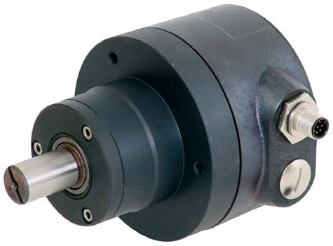
                                                                Der Messumformer KINAX WT707-SSI erfasst kontaktlos
•   Der Hersteller haftet nicht für Schäden, die auf unsach-    die Winkelstellung einer Welle und stellt sie binary-codiert
    gemässe Behandlung, Modifikationen oder nicht bestim-        an der SSI-Schnittstelle zur Verfügung.
    mungsgemässe Anwendungen zurückzuführen sind.

                                                                3. Lieferumfang
1.3 Inbetriebnahme                                              1 Messumformer für Drehwinkel KINAX WT707-SSI

               • Einbau, Montage, Installation und In-
                                                                1 Betriebsanleitung deutsch, englisch, französisch
                  betriebnahme des Gerätes muss aus-
                  schliesslich durch eine Fachkraft ausge-
                  führt werden.                                 4. Technische Daten
               • Betriebsanleitung des Herstellers muss
                                                                4.1 Allgemeine Daten
                  beachtet werden.
                                                                Betriebsspannung:          10 – 30 V DC
               • Vor Inbetriebnahme der Anlage alle elek-
                  trischen Verbindungen überprüfen.             Stromaufnahme
                                                                ohne Last:                 typ. 50 mA (bei 24 V DC)
               • Wenn Montage, elektrischer Anschluss
                  oder sonstige Arbeiten am Gerät und an        Ausgangsschaltung:         SSI, RS 422
                  der Anlage nicht fachgerecht ausgeführt       Signalcodierung:           Binär-Code
                  werden, kann es zu Fehlfunktionen oder
                                                                Max. Auflösung:             12 Bit (1 Messschritt = 5'16")
                  Ausfall des Gerätes führen.
                                                                Fehlergrenze:              ± 1°
               • Eine Gefährdung von Personen, eine Be-
                  schädigung der Anlage und eine Beschä-        Wiederholbarkeit:          0,3°
                  digung von Betriebseinrichtungen durch        Max. Taktfrequenz:         1 MHz
                  den Ausfall oder Fehlfunktion des Gerätes
                                                                Nullsetzsignal:            Nullsetzen: < 0,4 V, min. 2 ms
                  muss durch geeignete Sicherheitsmass-
                                                                                           Ruhestand: 3,3 V oder offen
                  nahmen ausgeschlossen werden.
                                                                Drehrichtung:              Mit Blick auf Flansch und
               • Das Gerät nicht ausserhalb der Grenz-                                     Drehung im Uhrzeigersinn
                  werte betreiben, welche in der Anleitung                                 ergeben sich steigende
                  angegeben sind.                                                          Positionswerte

                                                                                                                             3
4.2 Mechanische Daten                                                          Takteingang:
Material:                          Gehäuse:             Stahl                              encoder                                typical
                                   Rückenteil:          Aluminium                          circuit                                user
                                                                                           schematic                              interface
Steckverbinder:                    Metall (M12/8 Pol)
Gehäuseschutzart:                  IP 66 nach EN 60529                         +Vs                                                                     +Vs

Zulässige statische
Belastung der Welle:               Max. 1000 N (radial)                                         100 Ω         Clock
                                   Max. 500 N (axial)
                                   Bei Rüttelbetrieb wird zur Erhö-
                                   hung der Lebensdauer der Lager               0V                                                                     0V
                                   weitgehende Entlastung der Welle
                                   empfohlen

4.3 Umgebungsbedingungen
Temperaturbereich:                 – 20 bis + 70 °C
                                                                               4.7 Anschlussbelegung Stecker
Luftfeuchtigkeit:                  max. relative Feuchte im Jahres-
                                   mittel ≤ 95%                                                   Pin       Kabel-           Signale            Beschreibung
Transport- und                                                                                              farbe
Lagerungs-Temperatur: – 40 bis + 80 °C                                                             1        Weiss            0V               Betriebsspannung
Betriebshöhe:                      max. 2000 m
                                                                                                   2        Braun            +Vs              Betriebsspannung
Vibration:                         ≤ 300 m/s2 / 10 – 2000 Hz
                                   (nach IEC 60068-2-6)                                            3        Grün             Clock+           Taktleitung
Schock:                            ≤ 1000 m/s2 / 6 ms                                              4        Gelb             Clock–           Taktleitung
                                   (nach IEC 60068-2-27)
                                                                                                   5        Grau             Data+            Datenleitung
4.4 Abmessungen (ohne Stecker)                                                                     6        Rosa             Data–            Datenleitung
                                                      M6 × 15
                                                                                                   7        Blau             Zero             Nullsetzeingang
                                                                                                                                              Nicht
                                                                                                   8        Rot              open
Ø 62 f8

Ø 19 f6

                                                                                                                                              angeschlossen
 Ø 60

                                                                                                  Abschirmung                                 Gehäuse

             32,5
                    76,5                                        82 ±0,2
                           147                                   102
                                                                               5. Montage
                                                                               Der KINAX WT707-SSI kann auf drei verschiedene Mon-
4.5 Auslesen der Positionswerte
                                                                               tagearten montiert werden.

                                                                                                   Befestigungsart für Anbauteil
                                                                                     Unmittelbar                   Mit Fuss                      Mit Flansch
                                                                                        82 ±0,2                        71 ±0,2                         9

                                                                                            6,5
                                                                                                                                    90 ±0,2

                                                                                                                                                      11
                                                                                                    62 H8

                                                                                                                                                       0
                                                                                                                                                           H
                                                                                                                                                           7

Impulszeiten:                      T = 1 bis 10 μs /t1 = 0,5 bis 5 μs
                                                                                         120º                      9                                 130 ±0,2
                                   I2 = < 0,2 μs / t3 = > 12 bis 25 μs

4.6 Ausgangsschaltungen
                                                                               Die «unmittelbare» Befestigung verlangt 3 Schrauben
Datenausgang:                                                                  M6, wohingegen die «mit Fuss» und die «mit Flansch» je
            encoder                       typical                              4 Schrauben M8 mit Muttern erfordern. Die Schrauben
            circuit                       user                                 gehören nicht zum Lieferumfang, da ihre Längen durch
            schematic                     interface                            die von Fall zu Fall schwankende Dicke des Anbauteils am
                                                                               Messobjekt bestimmt wird.
+Vs                                                         +Vs

                                                                                                   • Schläge oder Schocks auf Gehäuse und
e.g.                             Data       100 Ω                                                       Welle vermeiden.
                                                            e.g.MC 3489
MAX 490                                                         SN 75175
                                                                AM 26 LS 32A                       • Gehäuse nicht verspannen.
    0V                                                          0V
                                                                                                   • Gerät nicht öffnen oder mechanisch ver-
                                                                                                        ändern.

4
6. Elektrische Anschlüsse                                                                                8. Ersatzteile
Zum Anschliessen der elektrischen Leitungen hat der Mess-                                                  Bezeichnung                                                           Bestell-Nr.
umformer einen Steckverbinder. Bei kundenspezifischer
Kabelkonfektionierung ausschliesslich geschirmte Leitungen                                                 Fuss                                                                   997 182
und Steckverbinder in EMV-Ausführung verwenden. Mon-                                                       Zur Befestigung des KINAX WT707-SSI
tageanleitung des Steckerlieferanten beachten.                                                             3 Sechskantschrauben M6 x 30
                                                                                                           3 Federringe B6
               • Das Gerät darf elektrisch nicht verändert                                                 3 Unterlegescheiben 6,4/12,5 x 1,6
                 werden und es dürfen keine Verdrahtungs-                                                  Flansch                                                                997 190
                 arbeiten unter Spannung vorgenommen                                                       Zur Befestigung des KINAX WT707-SSI
                 werden.                                                                                   3 Zylinderschrauben m I-6kt, M6 x 20
               • Der elektrische Anschluss darf unter Span-                                                3 Federringe B6
                 nung nicht aufgesteckt oder abgenommen                                                    Dichtung                                                               991 861
                 werden.                                                                                   Zwischen Rückenteil und Gehäuse als
                                                                                                           O-Ring 94,97 x 1,78

7. Elektrische Inbetriebnahme
•   Bei Verbrauchern mit hohen Störpegeln separate Span-                                                 9. Wartung
    nungsversorgung für das Gerät bereitstellen.                                                         Das Gerät arbeitet wartungsfrei.
•   Die gesamte Anlage EMV gerecht installieren. Einbauum-
    gebung und Verkabelung können die EMV des Gerätes
    beeinflussen.

                                     EG - KONFORMITÄTSERKLÄRUNG
                                     DECLARATION OF CONFORMITY
                  Dokument-Nr./                 WT707-SSI.DOC
                  Document.No.:

                  Hersteller/                   Camille Bauer AG
                  Manufacturer:                 Switzerland

                  Anschrift /                   Aargauerstrasse 7
                  Address:                      CH-5610 Wohlen

                  Produktbezeichnung/           Messumformer für Drehw inkel
                  Product name:                 Tranmitter for angular position

                  Typ / Type:                   Kinax WT 707-SSI

                  Das bezeichnete Produkt stimmt mit den Vorschriften folgender Europäischer Richtlinien
                  überein, nachgewiesen durch die Einhaltung folgender Normen:

                  The above mentioned product has been manufactured according to the regulations of the fol-
                  lowing European directives proven through compliance with the following standards:

                  Nr. / No.             R i c h t l i n i e / D i r e c t i ve
                  2004/108/EG           Elektromagnetische Verträglichkeit - EMV - Richtlinie
                  2004/108/EC           Electromagnetic compatibility -EMC directive

                  EMV /                 Fachgrundnorm /                                       M e s s ve r f a h r e n /
                  EMC                   Generic Standard                                      Measurement methods
                  Störaussendung /      EN 61000-6-4 : 2007                                   EN 55011 : 2007+A2:2007
                  Emission
                  Störfestigkeit /      EN 61000-6-2 : 2005                                   IEC    61000-4-2: 1995+A1:1998+A2:2001
                  Immunity                                                                    IEC    61000-4-3: 2002+A1:2002
                                                                                              IEC    61000-4-4: 2004
                                                                                              IEC    61000-4-6: 1996+A1:2001
                                                                                              IEC    61000-4-11:2004

                  Nr. / No.             R i c h t l i n i e / D i r e c t i ve
                  2006/95/EG            E l e k t r i s c h e B e t r i e b s m i t t e l z u r V e r we n d u n g i n n e r h a l b b e s t i m m t e r S p a n n u n g s -
                                        grenzen – Niederspannungsrichtlinie – CE-Kennzeichnung : 95
                  2006/95/EC            E l e c t r i c a l e q u i p m e n t f o r u s e wi t h i n c e r t a i n v o l t a g e l i m i t s – L o w V o l t a g e D i r e c -
                                        tive – Attachment of CE mark : 95

                  EN/Norm/Standard IEC/Norm/Standard
                  EN 61 010-1 : 2001    IEC 1010-1 : 2001

                  Ort, Datum /                        Wohlen, 2.Oktober.2008
                  Place, date:

                  Unterschrift / signature:

                 M. Ulrich                                      J. Brem
                 Leiter Technik                                 Qualitätsmanager

                                                                                                                                                                                               5
Mode d’emploi
KINAX WT707-SSI, convertisseur de mesure pour angle de rotation

1. Consignes de sécurité                                           1.4 Réparations et modifications

                                                                                      Les réparations et les modifications doi-
1.1 Symboles                                                                          vent être effectuées exclusivement par le
Les symboles de ce mode d’emploi indiquent les risques et                             fabricant. Le boîtier ne doit pas être ouvert.
ont la signification suivante:                                                         Toute intervention sur l’appareil annule la
                                                                                      garantie. Nous nous réservons le droit de
               Avertissement en cas de danger possible.                               procéder à des modifications dans le but
                                                                                      d’améliorer le produit.
               Le non-respect de ces instructions peut
               entraîner des dysfonctionnements.

               Le non-respect de ces instructions peut             1.5 Mise au rebut
               entraîner des dysfonctionnements et des
                                                                                      Les appareils et les composants doivent
               blessures.
                                                                                      être mis au rebut conformément aux di-
                                                                                      rectives locales en vigueur.
               Informations pour une utilisation conforme
               du produit.

                                                                   1.6 Transport et stockage

                                                                                      Les appareils ne doivent être transportés et
1.2 Utilisation conforme
                                                                                      stockés que dans leur emballage d’origine.
•   Le convertisseur de mesure KINAX WT707-SSI est un                                 Ne pas faire tomber les appareils et ne pas
    appareil de mesure de précision. Il sert à déterminer la                          les soumettre à des chocs.
    position des angles et rotations, à la préparation et la
    conversion des valeurs mesurées en signaux de sorties
    électriques pour l’appareil de suivi. Utiliser le capteur de   2. Description
    rotation uniquement à cet effet.
                                                                   Le convertisseur de mesure KINAX WT707-SSI détermine,
•   L’appareil est conçu pour être monté dans des installations    sans contact, la position d’angle d’un axe et la convertit en
    industrielles et est conforme à la norme EN 61010-1.           code binaire pour l’interface SSI.
•   Le fabricant décline toute responsabilité en cas de dom-
    mages entraînés par une manipulation inadaptée, des            3. Contenu de la livraison
    modifications ou des applications non conformes.
                                                                   1 convertisseur de mesure pour angle de rotation
                                                                     KINAX WT707-SSI
                                                                   1 mode d’emploi en allemand, anglais et français
1.3 Mise en service

               • La pose, le montage, l’installation et la mise    4. Données techniques
                 en service de l’appareil doivent impérative-
                 ment être confiés à un personnel qualifié.          4.1 Données générales

               • Respecter le mode d’emploi du fabricant.
                                                                   Tension de service:         10 à 30 V CC
                                                                   Consommation de
               • Contrôler tous les branchements électriques
                                                                   courant sans charge:        type. 50 mA (pour 24 V CC)
                 avant la mise en service de l’installation.
                                                                   Circuit de sortie:          SSI, RS 422
               • Si le montage, le raccordement électrique ou
                 les travaux sur l’appareil et l’installation ne   Codage du signal:           code binaire
                 sont pas effectués par un personnel qualifié,      Résolution max.:            12 bits (1 pas = 5'16")
                 cela peut entraîner des dysfonctionnements
                                                                   Limite d’erreur:            ± 1°
                 ou des pannes de l’appareil.
                                                                   Reproductibilité:           0,3°
               • Des mesures de sécurité appropriées doi-
                 vent permettre d’exclure tout risque de bles-     Fréquence d’horloge
                 sure, d’endommagement de l’installation ou        max.:                       1 MHz
                 des dispositifs de sécurité dû à une panne        Signal de remise à zéro: remise à zéro: < 0,4 V, 2 ms min.
                 ou à un dysfonctionnement de l’appareil.                                   repos: 3,3 V ou ouvert
                                                                   Sens de rotation:           en regardant la flasque et rotation
               • Respecter les valeurs limites indiquées dans                                  dans le sens des aiguilles d’une
                 la mode d’emploi pour le fonctionnement                                       montre, les valeurs de position sont
                 de l’appareil.                                                                croissantes

6
4.2 Données mécaniques                                                            Entrée d’horloge:
Matériau:                         boîtier:                 acier                             encoder                                  typical
                                  dos:                     aluminium                         circuit                                  user
                                                                                             schematic                                interface
Connecteurs:                      métal (M12/8 pôles)
Type de protection                                                                +Vs                                                                        +Vs
de boîtier:                       IP 66 selon EN 60529
Charge statique
autorisée de l’axe:               1000 N max. (radial)                                            100 Ω            Clock
                                   500 N max. (axial)
                                  En cas de fonctionnement dans
                                                                                   0V                                                                        0V
                                  un environnement soumis aux
                                  vibrations, il est recommandé
                                  d’éliminer toute charge sur l’axe
                                  afin d’optimiser la durée de vie des
                                  paliers
                                                                                  4.7 Raccordement des connecteurs
4.3 Conditions environnementales
Plage de température:             – 20 à + 70 °C                                                    Pin       Couleur                Si-            Description
Humidité de l’air:                humidité relative max. en moyenne                                           du câble              gnaux
                                  annuelle ≤ 95%
                                                                                                     1        Blanc             0V               Tension de service
Température de transport
et de stockage:        – 40 à + 80 °C                                                                2        Marron            +Vs              Tension de service
Hauteur d’exploitation: 2000 m max.                                                                  3        Vert              Clock+           Ligne du signal
Vibrations:                       ≤ 300 m/s2 / 10 à 2000 Hz                                                                                      d’horloge
                                  (selon CEI 60068-2-6)
                                                                                                     4        Jaune             Clock–           Ligne du signal
Choc:                             ≤ 1000 m/s2 / 6 ms                                                                                             d’horloge
                                  (selon CEI 60068-2-27)
                                                                                                     5        Gris              Data+            Ligne de données
4.4 Dimensions (sans connecteurs)
                                                         M6 × 15
                                                                                                     6        Rose              Data–            Ligne de données
                                                                                                     7        Bleu              Zero             Entrée de remise
                                                                                                                                                 à zéro
Ø 62 f8

Ø 19 f6
 Ø 60

                                                                                                     8        Rouge             open             Non raccordé
                                                                                                    Protection                                   Boîtier

            32,5
                   76,5                                            82 ±0,2
                          147                                       102
                                                                                  5. Montage
4.5 Lecture des positions                                                         Il existe trois possibilités de montage pour le KINAX WT707-
                                                                                  SSI.

                                                                                                                 Type de fixation
                                                                                    Montage direct                   Avec pied                      Avec flasque
                                                                                          82 ±0,2                         71 ±0,2                            9

                                                                                              6,5
                                                                                                                                       90 ±0,2

                                                                                                                                                           11
                                                                                                      62 H8

                                                                                                                                                             0
                                                                                                                                                                H
                                                                                                                                                                 7

Durée d’impulsion:                T = 1 à 10 μs /t1 = 0,5 à 5 μs
                                  I2 = < 0,2 μs / t3 = > 12 à 25 μs                        120º                                                            130 ±0,2
                                                                                                                      9

4.6 Circuits de sortie
Sortie de données:                                                                Le «montage direct» nécessite 3 vis M6. Pour la fixation
          encoder                            typical                              «avec pied» et la fixation «avec flasque», il faut utiliser 4 vis
          circuit                            user                                 M8 avec écrous. Ces vis ne sont pas fournies avec l’appareil
          schematic                          interface
                                                                                  car leur longueur varie selon l’épaisseur du support.
+Vs                                                            +Vs
                                                                                                     • Eviter tout choc et coup sur le boîtier et
                                                                                                          l’axe.
e.g.                            Data           100 Ω
                                                               e.g.MC 3489                           • Ne pas soumettre le boîtier à des tensi-
MAX 490                                                            SN 75175
                                                                   AM 26 LS 32A                           ons.
 0V                                                                0V                                • Ne pas ouvrir l’appareil ni procéder à des
                                                                                                          modifications mécaniques.

                                                                                                                                                                      7
6. Raccordements électriques                                                                            8. Pièces de rechange
Le convertisseur de mesure est doté d’un connecteur pour                                                   Désignation                                                            Référence.
le raccordement électrique. Pour la confection de câbles
spécifiques au client, utiliser exclusivement des câbles                                                    Pied                                                                    997 182
blindés et des connecteurs CEM. Respecter les instructions                                                 Pour la fixation de KINAX WT707-SSI
de montage du fabricant de connecteurs.                                                                    3 vis hexagonales M6 x 30
                                                                                                           3 rondelles grower B6
               • Ne pas effectuer de modifications élec-                                                    3 rondelles plates 6,4/12,5 x 1,6
                  triques sur l’appareil et ne pas réaliser                                                Flasque                                                                 997 190
                  de câblages lorsque l’appareil est sous                                                  Pour la fixation de KINAX WT707-SSI
                  tension.                                                                                 3 vis à tête cylindrique à six pans creux,
               • Ne pas brancher ou débrancher les rac-                                                    M6 x 20
                  cordements électriques lorsque l’appareil                                                3 rondelles grower B6
                  est sous tension.                                                                        Joint                                                                   991 861
                                                                                                           Entre le dos et le boîtier,
                                                                                                           joint torique 94,97 x 1,78
7. Mise en service électrique
•   En cas de niveaux de parasitage élevés, prévoir une
    alimentation séparée pour l’appareil.                                                               9. Entretien
•   Installer l’installation complète conformément aux normes                                           L’appareil fonctionne sans entretien.
    CEM. L’environnement et le câblage peuvent avoir une
    influence sur la CEM de l’appareil.

                                       EG - KONFORMITÄTSERKLÄRUNG
                                       DECLARATION OF CONFORMITY
                   Dokument-Nr./                 WT707-SSI.DOC
                   Document.No.:

                   Hersteller/                   Camille Bauer AG
                   Manufacturer:                 Switzerland

                   Anschrift /                   Aargauerstrasse 7
                   Address:                      CH-5610 Wohlen

                   Produktbezeichnung/           M e s s u m f o r m e r f ü r D r e h w in k e l
                   Product name:                 Tranmitter for angular position

                   Typ / Type:                   Kinax WT 707-SSI

                   Das bezeichnete Produkt stimmt mit den Vorschriften folgender Europäischer Richtlinien
                   überein, nachgewiesen durch die Einhaltung folgender Normen:

                   The above mentioned product has been manufactured according to the regulations of the fol-
                   lowing European directives proven through compliance with the following standards:

                    Nr. / No.            R i c h t l i n i e / D i r e c t i ve
                    2004/108/EG          Elektromagnetische Verträglichkeit - EMV - Richtlinie
                    2004/108/EC          Electromagnetic compatibility -EMC directive

                    EMV /                Fachgrundnorm /                                       M e s s ve r f a h r e n /
                    EMC                  Generic Standard                                      Measurement methods
                    Störaussendung /     EN 61000-6-4 : 2007                                   EN 55011 : 2007+A2:2007
                    Emission
                    Störfestigkeit /     EN 61000-6-2 : 2005                                   IEC    61000-4-2: 1995+A1:1998+A2:2001
                    Immunity                                                                   IEC    61000-4-3: 2002+A1:2002
                                                                                               IEC    61000-4-4: 2004
                                                                                               IEC    61000-4-6: 1996+A1:2001
                                                                                               IEC    61000-4-11:2004

                    Nr. / No.            R i c h t l i n i e / D i r e c t i ve
                    2006/95/EG           E l e k t r i s c h e B e t r i e b s m i t t e l z u r V e r we n d u n g i n n e r h a l b b e s t i m m t e r S p a n n u n g s -
                                         grenzen – Niederspannungsrichtlinie – CE-Kennzeichnung : 95
                    2006/95/EC           E l e c t r i c a l e q u i p m e n t f o r u s e wi t h i n c e r t a i n v o l t a g e l i m i t s – L o w V o l t a g e D i r e c -
                                         tive – Attachment of CE mark : 95

                    EN/Norm/Standard IEC/Norm/Standard
                    EN 61 010-1 : 2001   IEC 1010-1 : 2001

                   Ort, Datum /                        Wohlen, 2.Oktober.2008
                   Place, date:

                   Unterschrift / signature:

                   M. Ulrich                                     J. Brem
                   Leiter Technik                                Qualitätsmanager

8
Operating Instructions
KINAX WT707-SSI, Transmitter for Angular Position

1. Safety instructions                                             1.4 Repair work and modifications

                                                                                     Repair work and modifications shall exclusi-
1.1 Symbols                                                                          vely be carried out by the manufacturer. Do
The symbols in these instructions point out risks and have                           not open the housing of the device. In case of
the following meaning:                                                               any tampering with the device, the guaranty
                                                                                     claim shall lapse. We reserve the right of
                                                                                     changing the product to improve it.
                Warning in case of risks.
                Non-observance can result in malfunc-
                tioning.
                                                                   1.5 Disposal
                Non-observance can result in malfunctio-
                ning and personal injury.
                                                                                     The disposal of devices and components
                                                                                     may only be realised in accordance with
                                                                                     good professional practice observing the
                Information on proper product handling.                              country-specific regulations.

                                                                   1.6 Transport and storage

                                                                                     Transport and store the devices exclusively
1.2 Intended use                                                                     in their original packaging. Do not drop
                                                                                     devices or expose them to substantial
•   The KINAX WT707-SSI transmitter is a precision instru-                           shocks.
    ment. It serves the acquisition of angular position and
    rotation, processing and the provision of measured values
    as electric output signals for the downstream device. Use
    the transmitter for this purpose only.                         2. Brief description
•   The device is intended for installation in industrial plants   The KINAX WT707-SSI transmitter records the angular po-
    and meets the requirements of EN 61010-1.                      sition of a shaft without contact and makes it available in a
                                                                   binary code at the SSI interface.
•   Manufacturer is not liable for any damage caused by
    inappropriate handling, modification or any application
    not according to the intended purpose.
                                                                   3. Scope of delivery
                                                                   1 Transmitter for angular position KINAX WT707-SSI
                                                                   1 Operating instructions German, English, French
1.3 Commissioning

                • Installation, assembly, setup and commis-
                  sioning of the device has to be carried out      4. Technical data
                  exclusively by skilled workers.
                                                                   4.1 General data
                • Observe manufacturer’s operating instruc-
                  tions.                                           Power supply:              10 – 30 V DC

                • Check all electric connections prior to
                                                                   Power consumption
                  commissioning the plant.                         without load:              typ. 50 mA (at 24 V DC)
                                                                   Output circuit:            SSI, RS 422
                • If assembly, electric connection or other
                  work on the device and the plant are not         Signal coding:             Binary code
                  carried out properly, this may result in mal-    Max. resolution:           12 Bit (1 measuring step = 5'16")
                  functioning or breakdown of the device.
                                                                   Fault limit:               ± 1°
                • Safety measures should be taken to avoid
                                                                   Repeatability:             0.3°
                  any danger to persons, any damage of the
                  plant and any damage of the equipment            Max. clock rate:           1 MHz
                  due to breakdown or malfunctioning of            Zero setting signal:       Zero setting: < 0.4 V, min. 2 ms
                  the device.                                                                 Idle position: 3.3 V or open
                • Do not operate the device outside of             Direction of rotation:     Looking at the flange in clockwise
                  the limit values stated in the operating                                    rotation increasing position values
                  instructions.                                                               result

                                                                                                                                      9
4.2 Mechanical data                                                            Clocked input:
Material:                          Housing:             Steel                            encoder                                typical
                                   Back part:           Aluminium                        circuit                                user
                                                                                         schematic                              interface
Connectors:                        Metal (M12/8 pin)
Housing protection:                IP 66 according to EN 60529                 +Vs                                                                    +Vs

Permissible static load
on shaft:               Max. 1000 N (radial)                                                  100 Ω          Clock
                        Max. 500 N (axial)
                                   If subjected to vibration, the shaft
                                   load should be as low as possible            0V                                                                      0V
                                   to ensure optimum life of the bear-
                                   ings

4.3 Ambient conditions
Temperature range:                 – 20 to + 70 °C
                                                                               4.7 Pin configuration of connector
Humidity:                          Max. mean annual relative humidity
                                   ≤ 95%                                                        Pin        Cable           Signals             Description
Transport and                                                                                              colour
storage temperature:               – 40 to + 80 °C                                               1        White            0V               Power supply
Operating altitude:                max. 2000 m
                                                                                                 2        Brown            +Vs              Power supply
Vibration:                         ≤ 300 m/s2 / 10 – 2000 Hz
                                   (according to IEC 60068-2-6)                                  3        Green            Clock+           Clocking lead
Schock:                            ≤ 1000 m/s2 / 6 ms                                            4        Yellow           Clock–           Clocking lead
                                   (according to IEC 60068-2-27)
                                                                                                 5        Grey             Data+            Data line
4.4 Dimensions (without connector)                                                               6        Pink             Data–            Data line
                                                      M6 × 15
                                                                                                 7        Blue             Zero             Zero setting input
                                                                                                 8        Red              Open             Not connected
Ø 62 f8

Ø 19 f6
 Ø 60

                                                                                                Shield                                      Housing

             32,5
                    76,5                                        82 ±0,2
                           147                                   102

                                                                               5. Mounting
4.5 Readout of positional values                                               Three different ways to mount KINAX WT707-SSI are avail-
                                                                               able.

                                                                                              Mounting options for the attachment
                                                                                     Directly                Using a base                     Using a flange
                                                                                      82 ±0,2                        71 ±0,2                            9

                                                                                          6,5
                                                                                                                                  90 ±0,2

                                                                                                                                                    11
                                                                                                  62 H8

                                                                                                                                                        0
                                                                                                                                                         H
                                                                                                                                                            7

Impulse times:                     T = 1 to 10 μs /t1 = 0.5 to 5 μs
                                   I2 = < 0.2 μs / t3 = > 12 to 25 μs                  120º                      9                                 130 ±0,2

4.6 Output circuits
Data output:                                                                   Direct mounting requires 3 M6 screws, whereas the variants
            encoder                       typical                              using a base or a flange require 4 M8 screws and nuts.
            circuit                       user                                 Screws are not included in the scope of delivery since their
            schematic                     interface
                                                                               length is determined by the thickness of the attachment at
                                                                               the measured object, which fluctuates from case to case.
+Vs                                                         +Vs

                                 Data       100 Ω                                                • Avoid impacts or shocks on the housing
e.g.                                                        e.g.MC 3489
                                                                SN 75175
                                                                                                      and shaft.
MAX 490
                                                                AM 26 LS 32A
                                                                                                 • Do not deform housing.
 0V                                                             0V
                                                                                                 • Do not open or mechanically modify tghe
                                                                                                      device.

10
6. Electric connections                                                                                 8. Spare parts
The transmitter is equipped with a plug to connect the electric                                            Description                                                             Order No.
lines. In case of customized cable assembly, use shielded
lines and plugs in EMC-design exclusively. Observe assembly                                                Base                                                                    997 182
instructions of the plug supplier.                                                                         To fasten KINAX WT707-SSI
                                                                                                           3 M6 x 30 hexagon screws
                • Do not electricly modify the device nor                                                  3 spring washers B6
                  carry out any wiring work when energi-                                                   3 6.4/12.5 x 1.6 washers
                  sed.                                                                                     Flange                                                                  997 190
                • Do not plug in or unplug electric connection                                             To fasten KINAX WT707-SSI
                  when energised.                                                                          3 cheese head screws m I-6kt, M6 x 20
                                                                                                           3 spring washers B6
                                                                                                           Seal                                                                    991 861
                                                                                                           Between rear part and housing as
                                                                                                           an o-ring 94.97 x 1.78
7. Electric commissioning
•   Provide a separate power supply for the device in case
    of consumer loads with high interference levels.                                                    9. Maintenance
•   Install the entire plant in an EMC-compatible manner.                                               The device is free of maintenance.
    Installation environment and wiring can affect the EMC
    of the device.

                                       EG - KONFORMITÄTSERKLÄRUNG
                                       DECLARATION OF CONFORMITY
                    Dokument-Nr./                 WT707-SSI.DOC
                    Document.No.:

                    Hersteller/                   Camille Bauer AG
                    Manufacturer:                 Switzerland

                    Anschrift /                   Aargauerstrasse 7
                    Address:                      CH-5610 Wohlen

                    Produktbezeichnung/           M e s s u m f o r m e r f ü r D r e h w in k e l
                    Product name:                 Tranmitter for angular position

                    Typ / Type:                   Kinax WT 707-SSI

                    Das bezeichnete Produkt stimmt mit den Vorschriften folgender Europäischer Richtlinien
                    überein, nachgewiesen durch die Einhaltung folgender Normen:

                    The above mentioned product has been manufactured according to the regulations of the fol-
                    lowing European directives proven through compliance with the following standards:

                    Nr. / No.             R i c h t l i n i e / D i r e c t i ve
                    2004/108/EG           Elektromagnetische Verträglichkeit - EMV - Richtlinie
                    2004/108/EC           Electromagnetic compatibility -EMC directive

                    EMV /                 Fachgrundnorm /                                       M e s s ve r f a h r e n /
                    EMC                   Generic Standard                                      Measurement methods
                    Störaussendung /      EN 61000-6-4 : 2007                                   EN 55011 : 2007+A2:2007
                    Emission
                    Störfestigkeit /      EN 61000-6-2 : 2005                                   IEC    61000-4-2: 1995+A1:1998+A2:2001
                    Immunity                                                                    IEC    61000-4-3: 2002+A1:2002
                                                                                                IEC    61000-4-4: 2004
                                                                                                IEC    61000-4-6: 1996+A1:2001
                                                                                                IEC    61000-4-11:2004

                    Nr. / No.             R i c h t l i n i e / D i r e c t i ve
                    2006/95/EG            E l e k t r i s c h e B e t r i e b s m i t t e l z u r V e r we n d u n g i n n e r h a l b b e s t i m m t e r S p a n n u n g s -
                                          grenzen – Niederspannungsrichtlinie – CE-Kennzeichnung : 95
                    2006/95/EC            E l e c t r i c a l e q u i p m e n t f o r u s e wi t h i n c e r t a i n v o l t a g e l i m i t s – L o w V o l t a g e D i r e c -
                                          tive – Attachment of CE mark : 95

                    EN/Norm/Standard IEC/Norm/Standard
                    EN 61 010-1 : 2001    IEC 1010-1 : 2001

                   Ort, Datum /                         Wohlen, 2.Oktober.2008
                   Place, date:

                    Unterschrift / signature:

                   M. Ulrich                                      J. Brem
                   Leiter Technik                                 Qualitätsmanager

                                                                                                                                                                                             11
12
Sie können auch lesen