CSN Flanschheizkörper CSN Flange Heaters CSN Durchlauferhitzer CSN Flow Heaters - seit 1829
←
→
Transkription von Seiteninhalten
Wenn Ihr Browser die Seite nicht korrekt rendert, bitte, lesen Sie den Inhalt der Seite unten
Unabhängigkeit = Ressourcen x Innovation

                                    seit 1829 unter Strom

CSN       Flanschheizkörper
      ®

CSN   ®
          Flange Heaters
CSN       Durchlauferhitzer
      ®

CSN   ®
          Flow Heaters

seit 1829

                                        EW 2.92
                                          EW 2.92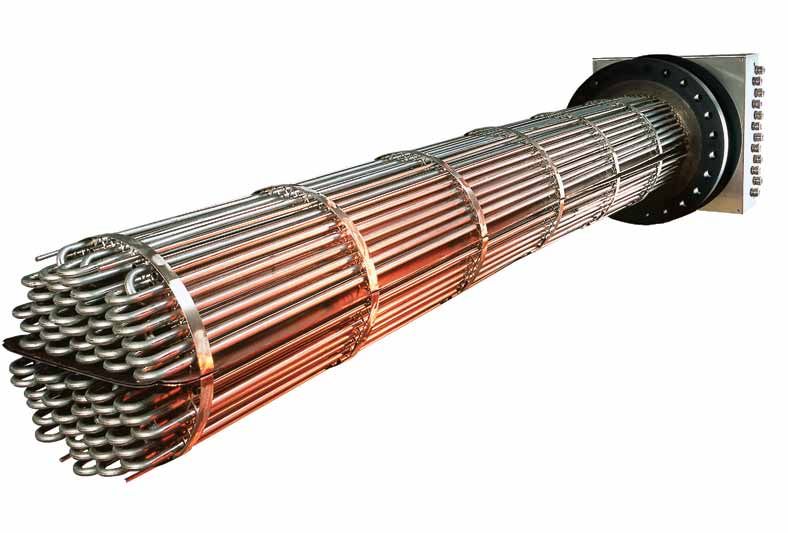
CSN Flanschheizkörper
CSN Flange Heaters

CSN Flanschheizkörper
werden mit hochverdichteten Rohrheizkörpern in den Durchmessern 8,5 mm, 11,5 mm oder 16 mm gefertigt.
Typische Anwendungsfelder sind in der chemischen Industrie, dem Schiffbau, der Bahnindustrie, der Kunststoffindustrie sowie der
Wärmeübertragungstechnologie.
CSN Flanschheizkörper gewährleisten eine lange Lebensdauer durch den Einsatz prozessoptimierter Rohrheizkörper mit Giso-Verschluss.
CSN Flanschheizkörper sind sowohl für flüssige Medien wie Wasser, verschiedene Öle, Laugen etc. als auch für Gase (Luft, Stickstoff,
Rauchgase) hervorragend geeignet. Sie zeichnen sich durch einen hohen Wirkungsgrad (direkte Erwärmung des Mediums) und durch minimale
Wartungskosten aus.
Produktvorteile:
Hervorragende Korrosionsbeständigkeit durch an den Prozess angepasste Heizkörperwerkstoffe. Hohe Isolationseigenschaften im Langzeit-
bereich bei Verwendung des Giso-Verschlusses.
Ausführungen:
Hochverdichtete U-förmig gebogene CSN Rohrheizkörper werden in Flansche bis DN 800 eingeschweisst, hart verlötet oder auswechselbar
montiert.Die verwendeten Rohrheizkörper sind auf Wunsch nach dem Giso-Verfahren verschlossen. Isolationswiderstände im Gigaohm-
bereich werden erreicht. Verschiedene Edelstahlwerkstoffe für unterschiedliche Medien- und Temperaturanforderungen stehen zur Verfügung.
Heizleistungen realisieren wir nach Kundenwunsch bis in den Megawattbereich. Für eine präzise Temperaturüberwachung stehen
Thermoelemente, PT 100 oder mechanische Regler bzw. Temperaturbegrenzer zur Verfügung. Die Schaltungsart und Anzahl der
Schaltgruppen ist individuell in Absprache mit dem Kunden realisierbar.

CSN flange heaters
are manufactured with high-compression tubular heating elements in the diameters 8.5 mm, 11.5 mm or 16 mm.
Typical areas of application are the chemical industry, shipbuilding, railroad industry, plastics industry and the heat transfer technology.
CSN flange heaters ensure a long service life by employing process optimized tubular heating elements with GISO closure.
CSN flange heaters are uniquely suitable, both for liquid media such as water, various oils, caustic solution, etc. as well as for gases (air,
nitrogen, smoke gases). They are marked by a high degree of efficiency (direct heating of the medium) and minimum maintenance costs.
Product benefits:
Superb corrosion resistance through heating element materials that have been adapted to the process.
High insulation properties in the long range when using the GISO closure.
Versions:
High-compression U-shaped bent CSN tubular heating elements are welded into flanges up to DN 800, hard soldered or installed
interchangeably. The tubular heating elements used can be closed using the GISO process if desired. Insulation resistances in the gigaohm
range are achieved.
Various special steel materials are available for different media and temperature requirements.
If requested by the customer, we realize heating capacities into the megawatt range.
Thermocouples, PT 100 or mechanical regulators or temperature limiters are available for precise temperature control.
The connection method and number of connection groups can be implemented according to customer specifications.
CSN Flanschheizkörper
Typenreihe 96 F/…
CSN Flanschheizkörper werden in der Verfahrentechnik, Reinigungstechnik, chemischen Industrie, Kunststoffindustrie, sowie im Maschinenbau- und Schiffbau
verwendet.
Anwendung:
CSN Flanschheizkörper eignen sich insbesondere zum Aufheizen von Wasser, Laugen, Wärmeübertragungsflüssigkeiten, Schweröl, Bitumen, Turbinenöl, Hydrauliköl
strömender oder ruhender Luft, nicht brennbare Gase oder Dämpfe,
Technische Daten:
Nennleistungen: bis 1000 kW Nennweite: DN 80 bis DN 800
Abstufung: nach Vereinbarung Nenndruck: PN 6 bis PN 100
Betriebstemperatur: Einbaulänge: bis max. 3500 mm
Flüssigkeiten bis 520°C Nennspannung: bis 1100 Volt 3~
Gasförmige Medien: bis 650°C
Aufbau:
CSN Flanschheizkörper bestehen im wesentlichen aus:
Hochverdichteten CSN Rohrheizkörpern in den Durchmessern 8,5; 11,5; 16 mm, Blindflansch, Distanz- oder Umlenkblechen, Anschlusshaube,
Thermostate , Temperaturfühler, Anschlussklemmen und Kabelverschraubungen.
CSN Rohrheizkörper:
Die hochverdichteten Rohrheizkörper werden nach DIN 44874, 44875 bzw. in Anlehnung daran, gefertigt.
Über den CSN Giso-Verschluss wird der hohe Isolationswiderstand des Rohrheizkörpers auf Dauer sichergestellt.
Je nach Anwendung fertigen wir nachfolgende Rohrheizkörper:
Werkstoff Rohrheizkörper Ø 8,5 Ø 11,5 Ø 16 Oberflächentemperatur
Kupfer X 250° C
1.4404 AISI 316L X 750° C
1.4541 AISI 321 X 750° C
1.4571 AISI 316Ti X X X 750° C
1.4828 AISI 309 X X X 900° C
1.4876 Incoloy 800 X X 950° C
2.4858 Incoloy 825 X 750° C
Blindflansche:
Die verwendeten Flansche entsprechen DIN 2527 Form ”B”. Andere Flansche z.B. nach ASME oder Sonderflansche werden realisiert.
Anschlusshaube:
Die Anschlusshaube besteht aus einem eckigen oder zylindrischen Gehäuse. Bei Temperauren bis 100°C wird die Anschlusshaube direkt mit dem Blindflansch
verbunden. Bei höheren Temperaturen wird zwischen Blindflansch und Anschlusshaube eine Kühlstrecke vorgesehen.
Mediumtemperatur °C Ausführung Kühlstrecke mm Kühlbleche Anzahl
~ 100 I - -
< 150 II 120 1
< 250 II 200 2
< 350 II 400 4
> 350 II wird individuell festgelegt wird individuell festgelegt
Thermostate / Temperaturfühler:
Zur Temperaturüberwachung verwenden wir Kapillarrohrregler und –Begrenzer, Sicherheitstemperaturbegrenzer, Widerstandsthermometer oder Thermoelemente.
Kabelverschraubungen:
Die Kabelverschraubungen entsprechen der Schutzart IP 54. Bei höheren Anforderungen werden Spezialverschraubungen der Schutzart IP 68 verwendet.
Anschlussklemmen:
Je nach Leistung und Abstufung sind für den elektrischen Anschluss Schienensysteme, Anschlussbolzen oder Anreihklemmen vorgesehen.
Dauerhafte Verbindungen:
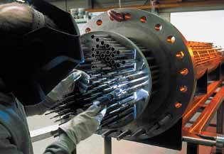
Abhängig vom Einsatzzweck werden Rohrheizkörper und Fühlerschutzrohre entweder eingeschweißt oder eingelötet. Das Einschweißen erfolgt im WIG-Verfahren.
Die Schweißarbeiten werden durch qualifiziertes Schweißpersonal (DIN EN 287/ASME IX) durchgeführt. Gültige Verfahrensprüfungen nach DIN EN 288 und ASME
IX liegen vor.
Zeugnisbelegung / Abnahmen
CSN Flanschheizkörper können mit Abnahmeprüfzeugnis EN 10204/3.1B über die verwendeten Werkstoffe, Druckprobe und über die elektrischen Daten
(z.B. Isolationswiderstand) geliefert werden.
Die Herstellung erfolgt entsprechend den Maßgaben der Richtlinie 97/23/EG (Druckgeräterichtlinie).
Auf Wunsch sind weitere Abnahmen und Zeugnisbelegungen möglich, z.B. Schwingungs- und Schockprüfung nach DIN EN 61373.
Qualitätsstandards
AD 2000-Merkblatt HP 0 / DIN EN 729-3, Reg.-Nr. 04 202 H 460 03 0025
Zertifikat nach DIN EN ISO 9001:2000 Zertifikat Register Nr. 041006676
Q1 Lieferant der Deutschen Bahn AG
Zertifizierung QM-System gemäß Richtlinie 97/23/EG
(Druckgeräterichtlinie) nach Modul D, D1 und H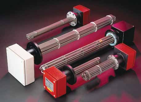
CSN flange heaters
Type series 96 F/…

CSN flange heaters are used in process control, cleaning technology, chemical industry, plastics industry as well an in mechanical engineering and shipbuilding.
Application:
CSN flange heaters are particularly suitable for heating water, caustic solutions, heat transfer liquids, heavy oil, bitumen, turbine oil, hydraulics oil, flowing air, resting
air, non-combustible gases or vapors.

Technical data:
Nominal output:      up to 1000 kW                                                Nominal width:           DN 80 to DN 800
Gradation:           per agreement                                                Nominal pressure:        PN 6 to PN 100
Operating temperature:                                                            Installation length:     up to max. 3500 mm
Liquids:             up to 520 °C                                                 Rated voltage:           up to 1100 Volt 3~
Gaseous media:       up to 650°C

Structure:
CSN flange heaters are essentially made up of:
High-compression CSN tubular heating elements in the diameters 8.5, 11.5, 16 mm, blind flange, spacer sheets or deflector plates, connection box, thermostat,
temperature probe, terminal clamps and screwed cable glands.
CSN tubular heating elements:
The high-compression tubular heating elements are manufactured according to or similar to DIN 44874, 44875.
With the help of the CSN GISO1 Closure, the high insulation resistance of the tubular heating element is permanently ensured.
Depending on the application, we manufacture the following tubular heating elements:

  Material                                    Tubular Heating element Ø 8,5                       Ø 11,5          Ø 16         Surface temperature
  Copper                                                                            X                                          250° C
  1.4404 AISI 316L                                                                  X                                          750° C
  1.4541 AISI 321                                                                   X                                          750° C
  1.4571 AISI 316Ti                                                                 X              X               X           750° C
  1.4828 AISI 309                                                                   X              X               X           900° C
  1.4876 Incoloy 800                                                                X              X                           950° C
  2.4858 Incoloy 825                                                                X                                          750° C

Blind flanges:
The flanges used correspond to DIN 2527 Form ”B”. Other flanges, e.g., according to ASME or special flanges can be used.

Connection box:
The connection box consists of a square or cylindrical housing. For higher temperatures up to 100 °C, the connection box is connected directly with the blind flange.
For higher temperatures, a cooling zone is incorporated between blind flange and connection box.

 Medium temperature °C                       Design                                      Cooling zone mm                            Cooling plates Qty.
                  ~ 100                                         I                                         -                                          -
                  < 150                                        II                                        120                                         1
                  < 250                                        II                                        200                                         2
                  < 350                                        II                                        400                                         4
                  > 350                                        II                               determined individually                    determined individually

Thermostat / Temperature probe
For the temperature control, we use capillary tube regulators and limiters, safety temperature limiters, resistance bulb thermometers or thermocouples.

Screwed cable glands
The screwed cable glands correspond to protection type IP 54. For higher requirements, special screw connections of protection type IP 68 are used.

Terminal clamps:
Depending on the output and the gradation, track systems, terminal studs or modular terminals are used for the electrical connection.

Permanent connections:
Depending on the application purpose, tubular heating elements and sensor protection sheaths are either welded or soldered on.
Welding is done according to the TIG procedure. The welding jobs are performed by qualified welders (DIN EN 287/ASME IX). Applicable process inspections
according to DIN EN 288 and ASME IX are available.

Certificates / Inspections

CSN flange heaters can be supplied with inspection certificates EN 10204/3.1B on the materials used, on pressure testing and electrical data (e.g., insulation
resistance).

Manufacturing follows the specifications of guideline 97/23/EG (Pressure equipment guideline)
Upon request, other inspections and confirming certificates can be performed or issued, respectively, e.g., vibration and shock testing according to DIN EN 61373.

Quality standards
AD 2000-Technical bulletin HP 0 / DIN EN 729-3, Reg.-No. 04 202 H 460 03 0025
Certificate according to DIN EN ISO 9001:2000 Certificate Register No. 041006676
Q1 Supplier of the Deutsche Bahn AG (German Railroad)
Certification QM System according to guideline 97/23/EG
(Pressure equipment guideline) according to module D, D1 and H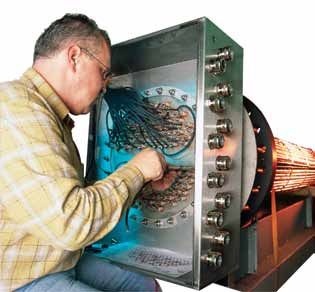
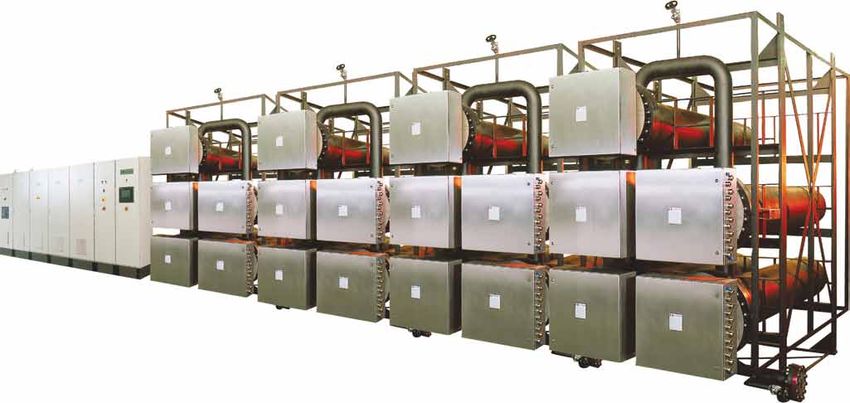
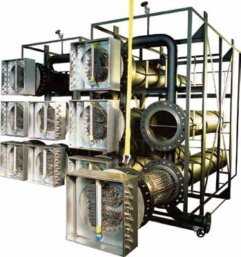
CSN Durchlauferhitzer
CSN Flow Heaters
CSN Durchlauferhitzer für verfahrenstechnische Prozesse
Typische Anwendungsfelder sind in der chemischen-petrochemischen Industrie, der Bahn- und Schiffsindustrie, im Machinen- und Anlagenbau.
CSN Durchlauferhitzer fertigen wir in enger Absprache mit unseren Kunden von einigen Watt bis Megawatt, unterschiedliche Schaltstufen realisieren
wir nach Kundenwunsch. Anlagen im explosionsgefährdeten Umfeld fertigen wir in den Zündschutzarten “EEx d” , “EEx de” , “EEx e”. CSN
Durchlauferhitzer fertigen wir auf Wunsch mit optimal abgestimmten Prozesssteuerungen. Sprechen Sie mit uns über zweckmäßige Regel- und
Steuerungsmöglichkeiten. Schniewindt ist durch Lloyd´s Register zertifiziert Geräte nach der Druckgeräterichtlinie 97/23/EG herzustellen, ein
Zertifikat des TÜV bescheinigt uns die Voraussetzungen für schweisstechnische Verfahren nach AD 2000-Merkblatt HP 0 / DIN EN 729-3.
Produktvorteile:
Vielseitige Einsatzmöglichkeiten bei der elektrischen Beheizung von Fluiden und gasförmigen Medien, hochwertige elektrische CSN Rohrheizkörper
aus dem Haus Schniewindt und eine auf den jeweiligen Anwendungsprozess abgestimmte Oberflächenbelastung in Verbindung mit der Verwendung
hochwertiger Edelstähle gewährleisten eine lange Lebensdauer, hohen Wirkungsgrad durch direkte Mediumerwärmung, einfache Bedienbarkeit und
geringe Wartungskosten.
Ausführungen:
Hochverdichtete U-förmig gebogene CSN Rohrheizkörper werden in Flansche bis DN 800 eingeschweisst,hart verlötet oder auswechselbar montiert
und mit zylindrischen Behältern oder Druckbehältern mechanisch fest verbunden. Die Behälter werden je nach Kundenforderung mir Rohrstutzen, Rohrmuffen
oder Vorschweissflanschen ausgeführt. Die Anschlusshauben erfüllen die Schutzart IP 65. Die Herstellung der CSN Durchlauferhitzer erfolgt entsprechend den
Maßgaben der Richtlinie 97/23/EG (Druckgeräterichtlinie), die verwendeten CSN Rohrheizkörper in den Durchmessern 8,5 mm, 11,5 mm oder 16 mm sind
auf Wunsch nach dem Giso-Verfahren verschlossene Heizelemente mit einer Isolationsfestigkeit Gigaohm je Rohrheizkörper. Verschiedene Edelstahlwerkstoffe
für unterschiedliche Medien stehen zur Verfügung. Heizleistungen realisieren wir nach Kundenwunsch bis in den Megawattbereich. Für eine präzise
Temperaturüberwachung stehen Thermoelemente, PT 100 oder mechanische Regler bzw. Temperaturbegrenzer zur Verfügung.

CSN flow heaters for process control applications
Typical areas of application are the chemical/petrochemical industry, railroad and shipping industry, in machinery and plant construction.
We manufacture CSN flow heaters in close cooperation with our customers, from only a few watt up to megawatt, we can implement different switch
steps according to customer request. We manufacture installations in explosion hazard environments also in the types of protection “EEx d” ,
“EEx de”, “EEx e”. Upon request, we produce CSN flow heaters with optimally coordinated process controls. Please contact us to discuss appropriate
regulating and control options. Schniewindt is certified by the Lloyd’s register, to manufacture equipment according to the pressure equipment
guideline 97/23/EG, a certificate of the TÜV (Technical Monitoring Agency) certifies that we meet the prerequisites for welding processes according to
AD 2000 Technical bulletin HP 0 / DIN EN 729-3.
Product benefits:
A wide range of possible applications with the electric heating of fluids and gaseous media, high-quality electrical CSN tubular heating elements
from Schniewindt corporation and a surface load balanced with the respective application process in conjunction with use of high quality special steels
ensure a long service life, a high degree of efficiency through direct medium heating, easy operation and low maintenance costs.
Versions:
High-compression U-shaped bent CSN tubular heating elements are welded into flanges up to DN 800, hard soldered or installed interchangeably
and joined firmly mechanically with cylindrical tanks or pressure tanks. Depending on customer requirements, the tanks are equipped with connection
pieces, connecting sleeves or welding neck flanges. The connection boxes meet protection type IP 65. The production of the CSN flow heaters follows
the specifications of guideline 97/23/EG (pressure tanks guidelines). Upon request, the CSN tubular radiators in the diameters 8.5 mm, 11.5 mm or
16 mm can be in the form of closed heating elements according to the GISO process exhibiting an insulation strength of gigaohms per tubular heating
element. Various special steel materials are available for different media. If requested by the customer, we deliver heating capacities into the megawatt
range. Thermocouples, PT 100 or mechanical regulators or temperature limiters are available for precise temperature control.
CSN Durchlauferhitzer
Typenreihe 97 D/…
CSN Durchlauferhitzer werden in der Verfahrentechnik, Reinigungstechnik, chemischen Industrie,
Kunststoffindustrie, Maschinenbau, Bahn- und Schiffsindustrie usw. verwendet.
Anwendung:
CSN Durchlauferhitzer eignen sich insbesondere zum Aufheizen von Wasser, Laugen,
Wärmeübertragungsflüssigkeiten, Schweröl, strömender oder ruhender Luft, nicht brennbaren Gasen oder Dämpfen.
Auslegung:
Die optimale Bauform und Heizflächenbelastung in Verbindung mit der Filmtemperatur wird über
computergestützte Auslegungsprogramme realisiert.
Aufbau:
CSN Durchlauferhitzer bestehen im wesentlichen aus:
CSN Flanschheizkörper mit Anschlusshaube
aus Stahlblech oder Edelstahl. Eingebaut sind Anschlussklemmen sowie optional Temperaturüberwachungselemente.
Die Kühlstrecke zwischen Flansch und Anschlusshaube ist so gewählt, dass die Komponenten in der Anschlusshaube
nicht überhitzt werden können. Die elektrische Schutzart der Anschlusshaube mit metallischen metrischen
Kabelverschraubungen entspricht IP 54. IP 65 auf Wunsch lieferbar.
Erhitzergehäuse aus Stahl, Kesselblech oder Edelstahl, Eintritts- und Austrittsflansche werden in ihrer Lage und Dimensionierung den jeweiligen Anforderungen
angepasst. Dichtungen liefern wir je nach Anforderung oder Kundenwunsch.
Optionen:
Die Erhitzer können auf Wunsch mit folgenden Optionen versehen werden:
• Standfüße –mit Fest- oder Gleitlager –
• Befestigungs- oder Aufhängelaschen
• Wärmeisolierung
• Förderpumpe
• Optimierung der Strömungsgeschwindigkeit durch zusätzliche Einbauten
• Armaturen
• Schütz- oder Thyristorsteuerung
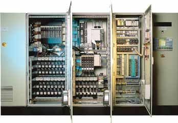
CSN Steuerungen
Für sämtliche CSN Wärmegeräte und Systeme fertigen wir optimal abgestimmte
Prozesssteuerungen.
Sprechen Sie mit uns über zweckmäßige Regel- und Steuerungsmöglichkeiten.
CSN Standard Schützsteuerungen bestehen aus:
• Schaltschrank
• Hauptschalter
• Lastsicherung
• Steuersicherung
• Stufensicherung
• Leuchtmelder
In wirtschaftlichen Heizsystemen wird die Regellast über Thyristorsteller geregelt,
somit ist eine genau dosierte Leistungszufuhr sichergestellt
CSN Thyristorsteuerungen bestehen aus:
• Schaltschrank
• Hauptschalter
• Halbleitersicherungen
• Leistungsschütz
• Halbleiterrelais in 3 Phasensparschaltung oder Thyristorsteller
• Steuerschalter
• Steuersicherung
• PID-Regler
• Leuchtmelder
Wir fertigen Prozesssteuerungen selbstverständlich auch nach Ihren individuellen
Ansprüchen!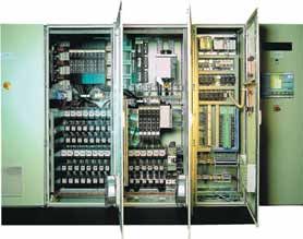
CSN flow heaters
Type series 97 D/…

CSN flow heaters are used in process control, cleaning technology, chemical industry, plastics industry,
mechanical engineering, railroad and shipbuilding industry, etc.

Application:
CSN flow heaters are particularly suitable for heating water, caustic solutions, heat transfer liquids, heavy oil,
flowing air, resting air, non-combustible gases or vapors.

Design:
The optimal structural design and heating surface load in connection with the film temperature is realized
with the help of computer based design programs.

Structure:
CSN flow heaters are essentially made up of:
CSN flange heating elements with connection box of steel sheets or special steel. Terminal clamps as well as optional
temperature control elements are installed. The cooling zone between flange and connection box is chosen to prevent
overheating of the components in the connection box. The electrical protection type of the connection box with metallic
metric screwed cable glands corresponds to IP 54. IP 65 can be supplied upon request.
Position and dimensions of the heater housing, made of steel, boiler plate or special steel, intake and outlet flanges, are adjusted according to the respective
requirements. We supply seals according to requirements or per customer request.

Options:
If requested, the heaters can be equipped with the following options:
      •     Support bases with fixed or friction bearings
      •     Mounting or suspension straps
      •     Heat insulation
      •     Supply pump
      •     Optimization of the velocity of flow through additionally installed elements
      •     Fittings
      •     Contactor or thyristor control

CSN Controls
We produce optimally coordinated controls for all CSN heating devices and systems.
Please contact us to discuss appropriate regulating and control options.

CSN Standard contactor controls consist of:
    •    Switch cabinet
    •    Main switch
    •    Load protection
    •    Control protection
    •    Step protection
    •    Light indicator

In an economic heating system, the standard loading is controlled via thyristor actuators,
an accurately controlled power supply is thereby ensured.

CSN Thyristor controls consist of:
    •    Switch cabinet
    •    Main switch
    •    Semi-conductor protections
    •    Power contactor
    •    Semi-conductor relays in 3 phase economy circuit or thyristor actuators
    •    Control switch
    •    Control protection
    •    PID Controller
    •    Light indicator

Of course, we also manufacture process controls according to your individual requirements!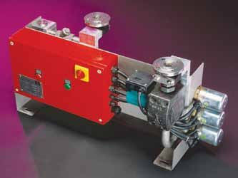
Elektro Vorwärmer als
                                                       Durchlauferhitzer für Fluidanwendungen

                 Für wässrige Lösungen besteht der Vorwärmer aus einem Strömungsrohr aus Aluminium LW = 63 mm mit
                                            themperaturbegrenzten Einschraubheizkörpern,
                                11,5 mm Ø einer Verschraubung G2“ und Rohrheizkörpern aus Edelstahl.
                                                 Der max. Betriebsdruck beträgt 15 Bar.

                                                         Belastung der Heizkörper : 6 Watt/cm2

  Typ                                 Leistung                        Spannung                   Gesamtlänge        Anzahl
                                      in Watt                           Volt                       in mm            Erhitzer

  97-ASW-0017                            1700                           400/2~                      390                1
  97-ASW-0021                            2100                           400/2~                      390                1
  97-ASW-0038                            3800                           400/2~                      590                1
  97-ASW-0050                            5000                           400/3~                      590                1
  97-ASW-0077                            7700                           400/3~                      790                1
  97-ASW-0100                            10000                          400/3~                      940                1
  97-ASW-0120                            12000                          400/3~                      1140               1
  97-ASW-0150                            15000                          400/3~                       790               2
  97-ASW-0200                            20000                          400/3~                       940               2
  97-ASW-0230                            23000                          400/3~                       790               3
  97-ASW-0240                            24000                          400/3~                      1140               2
  97-ASW-0300                            30000                          400/3~                       940               3
  97-ASW-0360                            36000                          400/3~                      1140               3
  97-ASW-0380                            38000                          400/3~                       650               4
  97-ASW-0400                            40000                          400/3~                       940               4
  97-ASW-0460                            46000                          400/3~                       790               6
  97-ASW-0480                            48000                          400/3~                      1140               4
  97-ASW-0500                            50000                          400/3~                       940               5
  97-ASW-0600                            60000                          400/3~                      1140               5
  97-ASW-0620                            62000                          400/3~                       940               6
Der Mindestdurchsatz für diese Geräte liegt bei ca. 2 m3/h

      Die max. Temperatur am Anschlußkopf darf 110 °C nicht überschreiten!
Electric pre-heater as
flow heaters for fluid applications
For aqueous solutions, the pre-heater comprises an aluminium jacket, I.D.= 63mm,
with G2”-threading, screw-in heating elements with temperature limiter, and stainless steel
tubular heating elements. Ø 11.5mm,
The max. operating pressure is 15 bar.
Surface load of the heating element: 6 Watt/cm2
Type Output Voltage Total length No. of
(W) (V) (mm) heaters
97-ASW-0017 1700 400/2~ 390 1
97-ASW-0021 2100 400/2~ 390 1
97-ASW-0038 3800 400/2~ 590 1
97-ASW-0050 5000 400/3~ 590 1
97-ASW-0077 7700 400/3~ 790 1
97-ASW-0100 10000 400/3~ 940 1
97-ASW-0120 12000 400/3~ 1140 1
97-ASW-0150 15000 400/3~ 790 2
97-ASW-0200 20000 400/3~ 940 2
97-ASW-0230 23000 400/3~ 790 3
97-ASW-0240 24000 400/3~ 1140 2
97-ASW-0300 30000 400/3~ 940 3
97-ASW-0360 36000 400/3~ 1140 3
97-ASW-0380 38000 400/3~ 650 4
97-ASW-0400 40000 400/3~ 940 4
97-ASW-0460 46000 400/3~ 790 6
97-ASW-0480 48000 400/3~ 1140 4
97-ASW-0500 50000 400/3~ 940 5
97-ASW-0600 60000 400/3~ 1140 5
97-ASW-0620 62000 400/3~ 940 6
The min. flow rate for these units is approx. 2 m3/h
The max. temperature at the terminal box is 110°C!Elektro Vorwärmer als
Durchlauferhitzer für Fluidanwendungen
Für Oel besteht der Vorwärmer aus einem Strömungsrohr aus Aluminium LW = 63 mm
mit themperaturbegrenzten Einschraubheizkörpern, 11,5 mm Ø
einer Verschraubung G2“ und Rohrheizkörpern aus Edelstahl.
Der max. Betriebsdruck beträgt 15 Bar.
Belastung der Heizkörper : 2 Watt/cm2
Typ Leistung Spannung Gesamtlänge Anzahl
in Watt Volt in mm Erhitzer
97-ASO-0006 600 230/400 3N 340 1
97-ASO-0009 900 230/400 3N 390 1
97-ASO-0013 1300 230/400 3N 490 1
97-ASO-0017 1700 230/400 3N 590 1
97-ASO-0025 2500 230/400 3N 790 1
97-ASO-0032 3200 230/400 3N 940 1
97-ASO-0041 4100 230/400 3N 1140 1
97-ASO-0050 5000 230/400 3N 790 2
97-ASO-0064 6400 230/400 3N 940 2
97-ASO-0068 6800 230/400 3N 590 4
97-ASO-0075 7500 230/400 3N 790 3
97-ASO-0082 8200 230/400 3N 1140 2
97-ASO-0085 8500 230/400 3N 590 5
97-ASO-0096 9600 230/400 3N 940 3
97-ASO-0100 10000 230/400 3N 790 4
97-ASO-0102 10200 230/400 3N 590 6
97-ASO-0123 12300 230/400 3N 1140 3
97-ASO-0125 12500 230/400 3N 790 5
97-ASO-0128 12800 230/400 3N 940 4
97-ASO-0150 15000 230/400 3N 790 6
97-ASO-0160 16000 230/400 3N 940 5
97-ASO-0164 16400 230/400 3N 1140 4
97-ASO-0192 19200 230/400 3N 940 6
97-ASO-0205 20500 230/400 3N 1140 5
97-ASO-0246 24600 230/400 3N 1140 6
Der Mindestdurchsatz für diese Geräte liegt bei ca. 2 m3/h
Die max. Temperatur am Anschlußkopf darf 110 °C nicht überschreiten!Electric pre-heater as
flow heaters for fluid applications
For oil, the pre-heater comprises an aluminium jacket, I.D.= 63mm,
with G2”-threading, screw-in heating elements with temperature limiter, and
stainless steel tubular heating elements. Ø 11.5mm,
The max. operating pressure is 15 bars.
Surface load of the heating element: 2 Watt/cm2
Type Output Voltage Total length No. of
(W) (V) (mm) heaters
97-ASO-0006 600 230/400 3N 340 1
97-ASO-0009 900 230/400 3N 390 1
97-ASO-0013 1300 230/400 3N 490 1
97-ASO-0017 1700 230/400 3N 590 1
97-ASO-0025 2500 230/400 3N 790 1
97-ASO-0032 3200 230/400 3N 940 1
97-ASO-0041 4100 230/400 3N 1140 1
97-ASO-0050 5000 230/400 3N 790 2
97-ASO-0064 6400 230/400 3N 940 2
97-ASO-0068 6800 230/400 3N 590 4
97-ASO-0075 7500 230/400 3N 790 3
97-ASO-0082 8200 230/400 3N 1140 2
97-ASO-0085 8500 230/400 3N 590 5
97-ASO-0096 9600 230/400 3N 940 3
97-ASO-0100 10000 230/400 3N 790 4
97-ASO-0102 10200 230/400 3N 590 6
97-ASO-0123 12300 230/400 3N 1140 3
97-ASO-0125 12500 230/400 3N 790 5
97-ASO-0128 12800 230/400 3N 940 4
97-ASO-0150 15000 230/400 3N 790 6
97-ASO-0160 16000 230/400 3N 940 5
97-ASO-0164 16400 230/400 3N 1140 4
97-ASO-0192 19200 230/400 3N 940 6
97-ASO-0205 20500 230/400 3N 1140 5
97-ASO-0246 24600 230/400 3N 1140 6
The min. flow rate for these units is approx. 2 m3/h
The max. temperature at the terminal box is 110°C!Elektrische Vorwärmaggregate Aufgabenstellung Verbrennungsmotoren, bei denen eine sofortige Betriebsbereitschaft wichtig ist, müssen vor dem Einschalten vorgewärmt werden. Die bekannten Kaltstartschwierigkeiten entfallen und der Motor kann sofort mit hoher Leistung betrieben werden. Ferner werden durch Kaltstarts bedingte Verschleißerscheinungen an der Maschine erheblich verringert. Typische Anwendungsbereiche für entsprechende Vorwärmanlagen sind z. B. Notstromaggregate (Dieselmaschine + Generator) oder Lokomotiven (Dieselmaschine für Antrieb). Gerätefunktion Bei stillstehendem, kalten Verbrennungsmotor wird die Kühlflüssigkeit durch den Kühlkreislauf des Verbrennungsmotors und durch den Durchlauferhitzer gepumpt. Die Umwälzung der Kühlflüssigkeit erfolgt hierbei durch die Pumpe des elektrischen Vorwärmaggregates. Über die Vorwärmung des Kühlmittelkreislaufs wird eine gleichmäßige Erwärmung des Motors bewirkt. Die Temperatur wird, nach Aufheizung des Kühlsystems, konstant auf der am Temperaturregler eingestellten Temperatur gehalten. Bei laufendem Motor wird der Erhitzer abgeschaltet. Die eingebaute Rückschlagklappe verhindert, dass bei laufendem Motor das Kühlwasser über das Vorwärmaggregat gepumpt wird. Geräteaufbau / Komponenten: Durchlauferhitzermodul mit kompaktem Aufbau Heizelemente: Einschraub-Heizkörper G2“ mit Rohrheizkörpern Ø 11,5 Umwälzpumpe Rückschlagklappe Einstellbarer Temperaturregler Sicherheitstemperaturbegrenzer Steuerschrank mit elektrischen Steuerungs- und Sicherungselementen Strömungskontrollschalter (optional) Sicherheitsventil (optional) Wärmeisolierung (optional) Standfüße Gerät ist funktionsbereit montiert und elektrisch verschaltet Vorteile bei der Verwendung Erheblich reduzierter Verschleiß des Verbrennungsmotors Startschwierigkeiten entfallen Sofortige Betriebsbereitschaft
Electric pre-heater assemblies

Tasks
Combustion engines requiring immediate operational readiness must be pre-heated before they are started.
The well-known cold-start problems are omitted and the engine can immediately operate at a high performance level.
Furthermore, cold start wear is considerably reduced. Typical fields of application for this type of pre-heater units
are e.g. emergency power units (Diesel engine + generator) or locomotives
(Diesel engine for propulsion).

Assembly functions
With a standing, cold combustion engine the cooling liquid is pumped through the cooling circuit of the engine and through
the flow heater. The pump of the electric pre-heater assembly circulates the cooling liquid.

The preheating of the cooling circuit provides a homogeneous heating of the engine. When the cooling system is heated,
the temperature is constantly maintained at the temperature set on the thermostat.

As soon as the engine is started, the pre-heater switches off. The integrated one-way valve prevents the cooling liquid
from being pumped through the pre-heater unit once the engine is started.

Assembly design/ components
Flow heater unit with compact design
Heating elements: screw-in heating element G2” with tubular heating elements Ø 11.5
Circulation pump
One-way valve
Adjustable thermostat
Safety temperature limiter
Control panel with electric control and safety fuses
Flow switch (optional)
Safety valve (optional)
Thermal insulation (optional)
Support
The assembly is delivered in operating condition

Advantages
Considerably reduced wear of the engine
No cold start problems
Immediate operational readiness
Typ      Leistung          Spannung            Ausführung/      Pumpe         Abmessung LxBxH      Gewicht
            KW                                   Abnahme                             mm               kg
 ASP        10/20                                                                945 x 296 x 427     ca. 66

                                         Nach Bestellvorlage
                        400V 3 ~ 50 Hz
 ASP        20/30                                              Max. 185 W        945 x 296 x 507     ca. 75
                                                               Föderleistung
 ASP        20/40                                              2m3/h 5,3 m       945 x 296 x 587     ca. 85
                                                                4m3/h 4 m
 ASP        20/50                                                                945 x 296 x 667     ca. 94

 ASP        36/60                                                                1145 x 296 x 667   ca. 102

Optional lieferbar:
- Pumpe mit höherer Förderleistung, z. B.:
  Max. 400 W
  Förderleistung
  4m3/h 5m
  8m3/h 4m
- Sicherheitsventil
- Montagerahmen
Type Output Voltage Execution/ Pump Dimensions LxWxH Weight
KW Approval mm kg
ASP 10/20 945 x 296 x 427 ca. 66
To customer specification
400V 3 ~ 50 Hz
ASP 20/30 Max. 185 W 945 x 296 x 507 ca. 75
flow rate
ASP 20/40 2m3/h 5,3 m 945 x 296 x 587 ca. 85
4m3/h 4 m
ASP 20/50 945 x 296 x 667 ca. 94
ASP 36/60 1145 x 296 x 667 ca. 102
Options:
- Pump with higher flow rate, e.g.:
Max. 400 W
Flow rate
4m3/h 5m
8m3/h 4m
- Safety valve
- Support frameSie können auch lesen