DREHGEBER BAUREIHE: 582 802 - 1102 - DRIVE-CLIQ - TR ELECTRONIC GMBH
←
→
Transkription von Seiteninhalten
Wenn Ihr Browser die Seite nicht korrekt rendert, bitte, lesen Sie den Inhalt der Seite unten
SIEMENS System-Schnittstelle
                                      D    Seite 2 - 20
   DRIVE-CLiQ                         GB   Page 21 - 39

  Drehgeber
  Baureihe:
    - 582
    - 802
    - 1102
                                                          TR-ECE-BA-DGB-0145 v01 01/27/2022

_Zusätzliche Sicherheitshinweise
_Installation
_Inbetriebnahme
_Fehlerursachen und Abhilfen

                                   Benutzerhandbuch
TR-Electronic GmbH
D-78647 Trossingen
Eglishalde 6
Tel.: (0049) 07425/228-0
Fax: (0049) 07425/228-33
E-mail: info@tr-electronic.de
www.tr-electronic.de
Urheberrechtsschutz
Dieses Handbuch, einschließlich den darin enthaltenen Abbildungen, ist urheber-
rechtlich geschützt. Drittanwendungen dieses Handbuchs, welche von den urheber-
rechtlichen Bestimmungen abweichen, sind verboten. Die Reproduktion, Überset-
zung sowie die elektronische und fotografische Archivierung und Veränderung bedarf
der schriftlichen Genehmigung durch den Hersteller. Zuwiderhandlungen verpflichten
zu Schadenersatz.
Änderungsvorbehalt
Jegliche Änderungen, die dem technischen Fortschritt dienen, vorbehalten.
Dokumenteninformation
Ausgabe-/Rev.-Datum: 01/27/2022
Dokument-/Rev.-Nr.: TR-ECE-BA-DGB-0145 v01
Dateiname: TR-ECE-BA-DGB-0145-01.docx
Verfasser: STB
Schreibweisen
Kursive oder fette Schreibweise steht für den Titel eines Dokuments oder wird zur
Hervorhebung benutzt.
Courier-Schrift zeigt Text an, der auf dem Display bzw. Bildschirm sichtbar ist und
Menüauswahlen von Software.
< > weist auf Tasten der Tastatur Ihres Computers hin (wie etwa ).
Marken
DRIVE-CLiQ ist eine geschützte Marke der SIEMENS AG
TR-Electronic GmbH 2018, All Rights Reserved Printed in the Federal Republic of Germany
Page 2 of 39 TR-ECE-BA-DGB-0145 v01 01/27/2022Inhaltsverzeichnis
Inhaltsverzeichnis .............................................................................................................................. 3
Änderungs-Index ................................................................................................................................ 4
1 Allgemeines ..................................................................................................................................... 5
1.1 Geltungsbereich ...................................................................................................................... 5
2 Zusätzliche Sicherheitshinweise ................................................................................................... 6
2.1 Symbol- und Hinweis-Definition .............................................................................................. 6
2.2 Organisatorische Maßnahmen ............................................................................................... 6
3 DRIVE-CLiQ Informationen ............................................................................................................. 7
4 Informationen / Dokumente zu den einzelnen Nutzungsphasen ................................................ 8
5 Installation ........................................................................................................................................ 9
5.1 Allgemeines ............................................................................................................................ 9
5.2 Mess-System - Leitung ........................................................................................................... 9
5.3 Anschluss ................................................................................................................................ 10
6 Inbetriebnahme ................................................................................................................................ 11
6.1 LED-Statusanzeige „RDY“ ...................................................................................................... 12
6.2 Parameter – Zugriff / Gesamtübersicht .................................................................................. 12
6.3 Für die Inbetriebnahme relevante Parameter / Register ........................................................ 14
6.3.1 Mess-System .......................................................................................................... 14
6.3.1.1 P0410 Drehrichtungsumkehr .................................................................................................. 14
6.3.1.2 R0482/R0483 Mess-System – Lageistwerte XIST1/XIST2 ..................................................... 15
6.3.2 Steuerung................................................................................................................ 15
7 Fehlerursachen und Abhilfen ......................................................................................................... 16
7.1 Optische Anzeigen .................................................................................................................. 16
7.2 Störungen und Warnungen..................................................................................................... 17
7.3 Sonstige Störungen ................................................................................................................ 18
8 Austauschen des Mess-Systems (Antriebsmotor) ...................................................................... 19
Printed in the Federal Republic of Germany TR-Electronic GmbH 2018, All Rights Reserved
01/27/2022 TR-ECE-BA-DGB-0145 v01 Page 3 of 39Änderungs-Index Änderungs-Index Änderung Datum Index Erstausgabe 06.12.2018 00 Kapitel „Sonstige Störungen“ keine paarig verdrillten Adern für Versorgung 27.01.2022 01 TR-Electronic GmbH 2018, All Rights Reserved Printed in the Federal Republic of Germany Page 4 of 39 TR-ECE-BA-DGB-0145 v01 01/27/2022
1 Allgemeines
Das vorliegende schnittstellenspezifische Benutzerhandbuch beinhaltet folgende
Themen:
Ergänzende Sicherheitshinweise zu den bereits in der Montageanleitung defi-
nierten grundlegenden Sicherheitshinweisen
Installation
Inbetriebnahme
Fehlerursachen und Abhilfen
Da die Dokumentation modular aufgebaut ist, stellt dieses Benutzerhandbuch eine Er-
gänzung zu anderen Dokumentationen wie z.B. Produktdatenblätter, Maßzeichnun-
gen, Prospekte und der Montageanleitung etc. dar.
Das Benutzerhandbuch kann kundenspezifisch im Lieferumfang enthalten sein, oder
kann auch separat angefordert werden.
1.1 Geltungsbereich
Dieses Benutzerhandbuch gilt ausschließlich für folgende Mess-System-Baureihen mit
DRIVE-CLiQ Schnittstelle:
582
802
1102
Die Produkte sind durch aufgeklebte Typenschilder gekennzeichnet und sind Bestand-
teil einer Anlage.
Es gelten somit zusammen folgende Dokumentationen:
siehe Kapitel „Mitgeltende Dokumente“ in der Montageanleitung
- Baureihe 582: www.tr-electronic.de/f/TR-ECE-BA-DGB-0035
- Baureihe 802: www.tr-electronic.de/f/TR-ECE-BA-DGB-0075
- Baureihe 1102: www.tr-electronic.de/f/TR-ECE-BA-DGB-0081
Produktdatenblätter
- Baureihe 582: www.tr-electronic.de/s/S019656
- Baureihe 802: www.tr-electronic.de/s/S019657
- Baureihe 1102: www.tr-electronic.de/s/S019658
optional: -Benutzerhandbuch
Printed in the Federal Republic of Germany TR-Electronic GmbH 2018, All Rights Reserved
01/27/2022 TR-ECE-BA-DGB-0145 v01 Page 5 of 39Zusätzliche Sicherheitshinweise
2 Zusätzliche Sicherheitshinweise
2.1 Symbol- und Hinweis-Definition
bedeutet, dass Tod oder schwere Körperverletzung eintre-
ten kann, wenn die entsprechenden Vorsichtsmaßnahmen
nicht getroffen werden.
bedeutet, dass eine leichte Körperverletzung eintreten kann,
wenn die entsprechenden Vorsichtsmaßnahmen nicht ge-
troffen werden.
bedeutet, dass ein Sachschaden eintreten kann, wenn die
entsprechenden Vorsichtsmaßnahmen nicht getroffen wer-
den.
bezeichnet wichtige Informationen bzw. Merkmale und An-
wendungstipps des verwendeten Produkts.
2.2 Organisatorische Maßnahmen
Dieses Benutzerhandbuch muss ständig am Einsatzort des Mess-Systems
griffbereit aufbewahrt werden.
Das mit Tätigkeiten am Mess-System beauftragte Personal muss vor Arbeits-
beginn
- die Montageanleitung, insbesondere das Kapitel „Grundlegende Sicher-
heitshinweise“,
- und dieses Benutzerhandbuch, insbesondere das Kapitel „Zusätzliche Si-
cherheitshinweise“,
gelesen und verstanden haben.
Dies gilt in besonderem Maße für nur gelegentlich, z. B. bei der Parametrie-
rung des Mess-Systems, tätig werdendes Personal.
TR-Electronic GmbH 2018, All Rights Reserved Printed in the Federal Republic of Germany
Page 6 of 39 TR-ECE-BA-DGB-0145 v01 01/27/20223 DRIVE-CLiQ Informationen
Die von der SIEMENS AG entwickelte Systemschnittstelle DRIVE-CLiQ ist ein Kern-
element des Antriebssystems SINAMICS S120 und auch weiterer Antriebe der
SINAMICS-Familie.
SINAMICS S120 ist innerhalb der Antriebsfamilie SINAMICS das Antriebssystem der
SIEMENS AG für Motion Control Anwendungen im Maschinen- und Anlagenbau.
Über DRIVE-CLiQ werden dabei alle die zur Lösung einer Anwendung erforderlichen
Systemkomponenten zu einem Antriebsverband miteinander verbunden. Über die of-
fene Geberschnittstelle DRIVE-CLiQ ist es somit möglich, auch das TR-Mess-System
in einfacher Weise in das Antriebssystem SINAMICS zu integrieren.
DRIVE-CLiQ setzt auf industriell bewährter Ethernet-Technik auf und bietet Echtzeit-
Übertragungsraten von 100 Mbit/s.
Durch das im Mess-System integrierte elektronische Typenschild wird gewährleistet,
dass das Mess-System durch die Steuerung automatisch in Betrieb (Autokonfigura-
tion) genommen werden kann und benötigt deshalb keine separate Konfigurations-
datei.
Das Mess-System ist mit folgenden festen Auflösungen verfügbar:
Singleturn Mess-System
Schritte pro Umdrehung: 4096 bis 262144 in 2er Potenzen (12 bis 18 Bits)
Multiturn Mess-System
Schritte pro Umdrehung: 4096 bis 262144 in 2er Potenzen (12 bis 18 Bits)
Anzahl der Umdrehungen: 4096 (12 Bits)
Für die Erst-Inbetriebnahme wird das von der Firma SIEMENS bereitgestellte so ge-
nannte „Inbetriebnahme-Tool STARTER“ empfohlen.
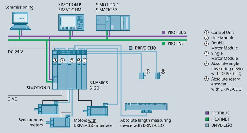
Abbildung 1: Konfigurationsschema SINAMICS S120 [Quelle: SIEMENS AG]
Weitere Informationen
Motion Control System SIMOTION:
www.siemens.com/simotion
Antriebsfamilie SINAMICS:
www.siemens.com/sinamics
Motion Control Systeme:
www.siemens.com/motioncontrol
Printed in the Federal Republic of Germany TR-Electronic GmbH 2018, All Rights Reserved
01/27/2022 TR-ECE-BA-DGB-0145 v01 Page 7 of 39Informationen / Dokumente zu den einzelnen Nutzungsphasen
4 Informationen / Dokumente zu den einzelnen Nutzungsphasen
Das Mess-System wird ausschließlich durch SIEMENS-eigene Komponenten (Soft-
ware, Hardware, Programm-Tools, Steuerungen, Kabel etc.) in Betrieb genommen,
bzw. betrieben. Aus diesem Grund ist es unabdingbar, in den einzelnen Nutzungs-
phasen des Mess-Systems, die von SIEMENS bereitgestellten Informationen bzw.
Dokumente zu nutzen.
Für das komplexe Antriebssystem SINAMICS S120 zeigt nachfolgende Tabelle bei-
spielhaft eine Übersicht der wichtigsten Dokumente und Tools:
Nutzungsphase Dokument/Tool
Projektierungs-Tool SIZER
Planen/Projektieren
Projektierungshandbücher Motoren
SINAMICS S120 Gerätehandbuch Control Units und er-
gänzende Systemkomponenten
SINAMICS S120 Gerätehandbücher für die einzelnen
Leistungsteile
Aufbauen/Montage SINAMICS S120 Gerätehandbuch AC Drive
SINAMICS S120 Gerätehandbuch Combi
SINAMICS S120M Gerätehandbuch Dezentrale Antriebs-
technik
SINAMICS HLA Systemhandbuch Hydraulic Drive
Inbetriebnahme-Tool STARTER
SINAMICS S120 Getting Started mit STARTER
SINAMICS S120 Inbetriebnahmehandbuch mit STARTER
Inbetriebsetzen
SINAMICS S120 Funktionshandbuch Antriebsfunktionen
SINAMICS S120/S150 Listenhandbuch
SINAMICS HLA Systemhandbuch Hydraulic Drive
SINAMICS S120 Inbetriebnahmehandbuch mit STARTER
Nutzen/Betreiben SINAMICS S120/S150 Listenhandbuch
SINAMICS HLA Systemhandbuch Hydraulic Drive
SINAMICS S120 Inbetriebnahmehandbuch mit STARTER
Instandhalten/Service
SINAMICS S120/S150 Listenhandbuch
Literaturverzeichnis SINAMICS S120/S150 Listenhandbuch
Weiterführende Informationen
Dokumentation bestellen/Druckschriftenübersicht
Weiterführende Links für den Download von Dokumenten
Dokumentation online nutzen
www.siemens.com/motioncontrol/docu
TR-Electronic GmbH 2018, All Rights Reserved Printed in the Federal Republic of Germany
Page 8 of 39 TR-ECE-BA-DGB-0145 v01 01/27/20225 Installation
5.1 Allgemeines
Leitungen in Maschinen und Schaltschränken unterliegen hohen Anforderungen wie
z.B. Biegebeständigkeit in Schleppketten, hochdynamische Bewegungen von Moto-
ren, Beständigkeit gegen Schneidöle und EMV-Eigenschaften. Daher sind nur solche
Leitungen zu verwenden, die für diese Einsatzfälle freigegeben sind, z.B. die von der
Firma SIEMENS angebotenen „MOTION-CONNECT“ - Leitungen.
Weitere Hinweise zur Planung, Aufbau und Installation sind dem SIEMENS Projektie-
rungshandbuch „EMV-Aufbaurichtlinie / Grundlegende Systemanforderungen“,
6FC5297-0AD30-0AP3 zu entnehmen.
Regeln zum Verdrahten mit DRIVE-CLiQ können z.B. dem SIEMENS Inbetriebnahme-
handbuch „SINAMICS S120“, 6SL3097-4AF00-0AP1 entnommen werden.
Siehe hierzu auch Kapitel 4 auf Seite 8.
5.2 Mess-System - Leitung
Die Mess-System – Leitung gehört mit zu den empfindlichsten Teilen einer Anlagen-
verdrahtung. Hier ist bei gestörten Signalen, z. B. bei Werkzeugmaschinen, mit Ober-
flächenfehlern oder sporadischen Fehlern der Maschine zu rechnen. Bei doppelt ge-
schirmten Mess-System - Leitungen ist der äußere Schirm beidseitig, der innere
Schirm einseitig nur am Antriebsverband aufzulegen.
Bei Mess-Systemen mit Steckverbindern ist der Schirm üblicherweise über den Ste-
cker angeschlossen. Bei besonders hohen Anforderungen, z. B. Umfeld mit sehr ho-
hen EMV-Pegeln, ist eine weitere Auflage dicht am Stecker empfehlenswert.
Die Schirmkontaktierung der DRIVE-CLiQ-Mess-System - Leitung erfolgt über den
Anschluss-Stecker.
Zusätzlich zu den DRIVE-CLiQ-Signalen besitzt die Leitung zwei Adern und Kontakte
für die 24V Versorgung des Mess-Systems. Die Stromversorgung und die Signalüber-
tragung erfolgt somit über ein Kabel.
Hierfür werden von der Firma SIEMENS bereits vorkonfektionierte DRIVE-CLiQ-
Signalleitungen „MOTION-CONNECT“ mit DC-24-V-Adern angeboten.
Zum Beispiel das Kabel (Bestell-Nr.: 6FX.002-2DC30-1DA0) als Basisleitung zwi-
schen dem DRIVE-CLiQ-Mess-System und dem SINAMICS S120 Motor Modules und
Power Modules:
Motorseitig mit RJ45-Stecker (Schutzart IP20) und Mess-System – seitig mit 8-poliger
M12-Buchse (Schutzart IP67), 30 m Leitungslänge.
Die maximale Leitungslänge mit beidseitigen RJ45-Steckern (IP20/IP67) beträgt
100 m, was auch der maximalen Summenleitungslänge für DRIVE-CLiQ entspricht.
Befindet sich auf einer Seite ein genormter 8-poliger M12-Stecker (IP67), beträgt die
maximale Leitungslänge nur noch 30 m!
Weitere Kabel-Varianten sind direkt von SIEMENS zu beziehen:
https://w3.siemens.com/mcms/mc-systems/de/automatisierung/motion-connect/Seiten/
verbindungstechnik-motion-connect.aspx.
Die Verwendung handelsüblicher Ethernet-Leitungen ist nur innerhalb des Steue-
rungsaufbaus möglich. Die Verbindung zum Mess-System sind mit dem speziellen
MOTION-CONNECT-Kabel mit aufgelegter Versorgungsspannung auszuführen.
Printed in the Federal Republic of Germany TR-Electronic GmbH 2018, All Rights Reserved
01/27/2022 TR-ECE-BA-DGB-0145 v01 Page 9 of 39Installation
5.3 Anschluss
Die Steckerbelegung entspricht den Vorgaben von SIEMENS und ist abhängig von
der Geräteausführung, deshalb ist bei jedem Mess-System auf dem Typenschild als
Steckerbelegungsnummer vermerkt. Bei der Auslieferung des Mess-Systems wird je-
weils eine gerätespezifische Steckerbelegung in gedruckter Form beigelegt.
Download:
www.tr-electronic.de/service/downloads/steckerbelegungen.html
TR-Electronic GmbH 2018, All Rights Reserved Printed in the Federal Republic of Germany
Page 10 of 39 TR-ECE-BA-DGB-0145 v01 01/27/20226 Inbetriebnahme
Für die Inbetriebnahme des Mess-Systems ist es erforderlich, dass die Inbetriebnah-
me des Antriebssystems SINAMICS bereits erfolgt ist. Die Inbetriebnahmevorberei-
tungen und die eigentliche Inbetriebnahme für das Antriebssystem SINAMICS werden
z.B. im SIEMENS Inbetriebnahmehandbuch „SINAMICS S120“, 6SL3097-4AF00-
0AP1 beschrieben.
Um das Mess-System in Betrieb nehmen zu können, wird ein PC oder PG mit dem
SIEMENS Inbetriebnahme-Tool STARTER benötigt. Wird die Verbindung vom PC/PG
über die Ethernet-Schnittstelle hergestellt, wird ein INTEL Ethernet-Adapter gefordert,
das Verbindungskabel muss dabei gekreuzt sein.
Systemvoraussetzungen, Installationsablauf und Online-Betrieb, sowie Informationen
zum Thema „Auswahl und Konfiguration von Gebern“, können ebenfalls dem
SIEMENS Inbetriebnahmehandbuch „SINAMICS S120“ entnommen werden.
Abbildung 2: Beispielhafter Komponentenaufbau – Mess-System - Inbetriebnahme
Nach dem ein Mess-System in das Projekt mit aufgenommen oder ersetzt wurde,
muss zum Abgleich des Mess-Systems mit dem Servomotor eine „Pol-Lage-
Identifikation“ und die „Automatische Reglereinstellung“ durchgeführt werden.
Die sogenannte „Pol-Lage-Identifikation“ Parameter P0431 (Ermittlung des Kommutie-
rungswinkeloffsets) ermittelt die elektrische Pol-Lage bei Synchronmotoren, die für die
feldorientierte Regelung benötigt wird. Die „Pol-Lage-Identifikation“ wird über den Pa-
rameter „P1990 Geberjustage Kommutierungswinkeloffset ermitteln“ gesteuert. Um
den Vorgang zu starten, muss der Parameter P1990 von „0“ auf „1“ gesetzt werden.
Die Rücksetzung erfolgt automatisch mit dem Abschluss der „Automatischen Regler-
einstellung“. Der ermittelte Kommutierungswinkeloffset muss anschließend gespei-
chert werden und wird dabei in Parameter P0431 eingetragen.
Nähere Informationen zur „Pol-Lage-Identifikation“ werden z.B. im SIEMENS Funkti-
onshandbuch, „SINAMICS S120“, 6SL3097-4AB00-0AP2 gegeben.
Die „Automatischen Reglereinstellung“ muss über die entsprechende Schaltfläche im
„Inbetriebnahme-Tool STARTER“ ausgeführt werden.
Vor Ausführung der Pol-Lage-Identifikation und der „Automatischen Reglereinstel-
lung“, müssen die Warnhinweise im SIEMENS Funktionshandbuch beachten wer-
den.
Printed in the Federal Republic of Germany TR-Electronic GmbH 2018, All Rights Reserved
01/27/2022 TR-ECE-BA-DGB-0145 v01 Page 11 of 39Inbetriebnahme
6.1 LED-Statusanzeige „RDY“
Das Mess-System verfügt optional über eine Bi-Color-LED „RDY = Ready“ mit den
Farben grün und rot bzw. orange, wenn grün und rot gleichzeitig leuchten.
Anlauf-Verhalten, wenn das Mess-System an die Steuerung angeschlossen ist:
Initialisierungsphase -> LED = rot für ca. 5 s
Verbindungsaufbau -> LED = orange für ca. 20 s
Normaler Betriebszustand, Mess-System OK -> LED = grün
Danach hängt die Anzeige vom Betriebszustand des Mess-Systems ab.
Farbe Status Beschreibung
- AUS Spannungsversorgung fehlt oder wurde unterschritten
AN
grün Normalbetrieb, Mess-System im Datenaustausch
statisch
AN
orange DRIVE-CLiQ Kommunikation wird hergestellt
statisch
AN
rot mindestens ein Mess-System - Fehler aufgetreten
statisch
grün /
orange
Mess-System wird über die Funktion „Sensor Module Erken-
oder 2 Hz
nung über LED“, Parameter P0144 = 1, angesprochen
rot /
orange
Entsprechende Maßnahmen im Fehlerfall siehe Kapitel „Optische Anzeigen“, Seite 16.
6.2 Parameter – Zugriff / Gesamtübersicht
Der Zugriff auf Parameter erfolgt generell über die entsprechenden Expertenlisten
im Inbetriebnahme-Tool STARTER. Die einzelnen Parameter sind dabei mit einer Zu-
griffsstufe belegt, mit der die Sichtbarkeit und die Änderungsmöglichkeiten gesteuert
werden.
Es gibt folgende Zugriffsstufen:
1. Standard
2. Erweitert
3. Experte
4. Service
Parameter mit dieser Zugriffsstufe sind durch ein Passwort geschützt.
5. Makro (Der Parameter kann nur über Makro geändert werden)
Die Zugriffsstufe, Datentyp etc., sowie eine komplette Beschreibung aller Parameter,
wird z.B. im SIEMENS Listenhandbuch SINAMICS S120/S150,
6SL3097-4AP00-0AP0 gegeben. Die Mess-System – eigenen Parameter sind im Pa-
rameterbereich P0400 bis P0499 zu finden.
TR-Electronic GmbH 2018, All Rights Reserved Printed in the Federal Republic of Germany
Page 12 of 39 TR-ECE-BA-DGB-0145 v01 01/27/2022Übersicht aller SINAMICS Parameter-Bereiche
Bereich
Beschreibung
von bis
0000 0099 Bedienen und Anzeigen
0100 0199 Inbetriebnahme
0200 0299 Leistungsteil
0300 0399 Motor
0400 0499 Geber
0500 0599 Technologie und Einheiten
0600 0699 Thermische Motorüberwachung und Motormodell, Max-Strom
0700 0799 Befehlsquellen und Klemmen der Control Unit, Messbuchsen
0800 0839 CDS-, DDS-Datensätze (z. B. Umschalten, Kopieren)
0840 0879 Ablaufsteuerung (z. B. Quelle für EIN/AUS1)
0880 0899 Steuer- und Zustandswörter
0900 0999 PROFIBUS/PROFIdrive
1000 1199 Sollwertkanal
1200 1299 Funktionen (z. B. Motorhaltebremse)
1300 1399 U/f-Steuerung
1400 1799 Regelung
1800 1899 Steuersatz
1900 1999 Leistungsteil- und Motoridentifizierung
2000 2099 Kommunikation (PROFIBUS)
2100 2199 Störungen und Warnungen, Überwachungen
2200 2399 Technologieregler
2900 2930 Festwerte (z. B. Prozent, Drehmoment)
3400 3699 Einspeiseregelung (Active Line Module)
3800 3899 Reibkennlinie
3900 3999 Verwaltungsparameter
4000 4199 Terminal Board, Terminal Module (z. B. TB30, TM31)
4200 4399 Terminal Module (z. B. TM15, TM17)
6000 6999 SINAMICS GM/SM/GL
7000 7499 Parallelschaltung von Leistungsteilen
7800 7899 EEPROM Schreib-Lese-Parameter
8500 8599 Daten- und Makroverwaltung
8600 8799 CAN-Bus
8800 8899 Communication Board
9300 9399 Safety Integrated
9400 9499 Parameterkonsistenz und -speicherung
9500 9899 Safety Integrated
9900 9949 Topologie
9950 9999 Diagnose intern
10000 10099 Safety Integrated
11000 11299 Freier Technologieregler 1, 2, 3
20000 20999 Freie Funktionsblöcke (FBLOCKS)
21000 25999 Drive Control Chart (DCC)
50000 53999 SINAMICS DC MASTER (Gleichstromregelung)
61000 61001 PROFINET
Printed in the Federal Republic of Germany TR-Electronic GmbH 2018, All Rights Reserved
01/27/2022 TR-ECE-BA-DGB-0145 v01 Page 13 of 39Inbetriebnahme
6.3 Für die Inbetriebnahme relevante Parameter / Register
6.3.1 Mess-System
Parameter Titel gemäß Listenhandbuch Default
8 bei 12 Bits
16 bei 13 Bits
32 bei 14 Bits
P0408 Rotatorischer Geber Strichzahl / Rot Geb Strichzahl (Grobauflösung) 64 bei 15 Bits
128 bei 16 Bits
256 bei 17 Bits
512 bei 18 Bits
P0410 Geber Invertierung Istwert 0
P0418 Feinauflösung Gx_XIST1 (in Bits) 11 Bits*
P0419 Feinauflösung Absolutwert Gx_XIST2 (in Bits) 11 Bits*
Multiturn 12
P0421 Absolutwertgeber rotatorisch Multiturn-Auflösung
Singleturn 1
P0423 Absolutwertgeber rotatorisch Singleturn-Auflösung 1218 Bits
P0431 Kommutierungswinkeloffset (siehe Kap. 6) -
R0465 Geber 1 Identnummer/Seriennummer -
CI: Signalquelle für Gebersteuerwort Gn_STW -
13
P0480 Bit 2 = 0: keine Ausgabe in R0483 (Gn_XIST2)
13
Bit 2 = 1: Ausgabe des Geberlageistwertes in R0483 (Gn_XIST2)
CO: Geberzustandswort Gn_ZSW -
13
R0481 Bit 2 = 0: keine Ausgabe in R0483 (Gn_XIST2)
13
Bit 2 = 1: Ausgabe des Geberlageistwertes in R0483 (Gn_XIST2)
R0482 CO: Geberlageistwert Gn_XIST1 -
R0483 CO: Geberlageistwert Gn_XIST2 -
* Um die volle Singleturn-Auflösung nutzen zu können, muss Parameter P418 und
P419 in der Inbetriebnahmephase grundsätzlich von den von SIEMENS vorge-
gebenen 11 Bits auf 9 Bits umgestellt werden.
6.3.1.1 P0410 Drehrichtungsumkehr
Wert Beschreibung Default
Mess-System – Position im Uhrzeigersinn steigend
0x00 X
(Blick auf Welle, Anflanschung)
Mess-System – Position im Uhrzeigersinn fallend
0x03
(Blick auf Welle, Anflanschung)
TR-Electronic GmbH 2018, All Rights Reserved Printed in the Federal Republic of Germany
Page 14 of 39 TR-ECE-BA-DGB-0145 v01 01/27/20226.3.1.2 R0482/R0483 Mess-System – Lageistwerte XIST1/XIST2
Über die Mess-System - Schnittstelle Gn_XIST1/Gn_XIST2 im Istwert-Telegramm des DRIVE-CLiQ
wird der Lageistwert zum Master übertragen und in den DRIVE-CLiQ Registern R482 bzw. R483 ge-
speichert.
Gn_XIST1, R482 Geberlageistwert setzt sich zusammen aus:
einem Absolutteil der Singleturn Position
Dies sind die Feinbits der Singleturnposition. Untere Bits der Singleturnposition (allgemein)
Singleturnpositions-Bits [10..0] / TR Singleturnpositions-Bits [8..0])
einem Inkrementellen Teil der Singleturn Position
Dies sind die Grobits der Singleturnposition. Obere Bits der Singleturnposition (TR-Mess-System)
Singleturnpositions-Bits [11..9] für 12 Bits Singleturn
···
Singleturnpositions-Bits [17..9] für 18 Bits Singleturn
Bei Multiturngebern einem Inkrementellen Teil der Multiturnposition
Die Inkrementellen Singleturn- und Multiturn-Positionen werden automatisch In der DRIVE-CLiQ
Schnittstelle berechnet und Ausgegeben.
Gn_XIST2, R483 Geberlageistwert Absolut:
Der Geberlageistwert Absolut Gn_XIST2 beinhaltet die gesamte Absolute Position des Drehge-
bers. Um diesen Wert im Register R483 angezeigt zu bekommen, muss zuvor im Parameter
P480 das Gebersteuerwort Gn_STW entsprechend gesetzt werden.
z.B. Zustandswort 1 über Register R2089 anwählen und im Register R2089 Bit[13] auf „1“ setzen.
Ist dies erfolgt so steht im Register R481 Geberzustandswort Gn_ZSW eine 2000H, und über
Register R483 kann die Absolutposition des Drehgeber ausgelesen werden.
Die Lageistwerte werden dabei nach dem Geberformat P979 gemäß PROFIdrive-
Antriebsprofil übertragen. Siehe Spezifikation der PROFIBUS Nutzerorganisation e.V. PRO-
FIdrive Profile, Bestell-Nr.: 3.172 und SIEMENS Funktionshandbuch -> „Steuer- und Zustandswörter
für Geber“.
6.3.2 Steuerung
Parameter Titel gemäß Listenhandbuch
P0010 Antrieb Inbetriebnahme Parameterfilter / Antr IBN Par_filt
R0061 CO: Drehzahlistwert ungeglättet / n_ist ungeglättet
P0187 Geber 1 Geberdatensatz Nummer / Geb 1 EDS Nummer
P0188 Geber 2 Geberdatensatz Nummer / Geb 2 EDS Nummer
P0189 Geber 3 Geberdatensatz Nummer / Geb 3 EDS Nummer
R0979 PROFIdrive Geberformat / PD Geberformat
P1990 Geberjustage Kommutierungswinkeloffset ermitteln / Geb_just Wink erm
R2089 CO: Binektor-Konnektor-Wandler Zustandswort senden / Bin/Kon ZSW senden
P2502 LR Geberzuordnung / Geberzuordnung
P2506 LR Längeneinheit LU pro Lastumdrehung / LU pro Lastumdr
P2507 LR Absolutwertgeberjustage Status / Abs_geb_just Sta
R2524 CO: LR LU/Umdrehung / LU/Umdrehung
R2526 CO/BO: LR Zustandswort / ZSW
Printed in the Federal Republic of Germany TR-Electronic GmbH 2018, All Rights Reserved
01/27/2022 TR-ECE-BA-DGB-0145 v01 Page 15 of 39Fehlerursachen und Abhilfen
7 Fehlerursachen und Abhilfen
7.1 Optische Anzeigen
Anzeigezustände und Blinkfrequenz, siehe Kapitel „ LED-Statusanzeige „RDY“ „ auf Seite 12.
Farbe Status Ursache Abhilfe
- Spannungsversorgung, Verdrah-
Spannungsversorgung fehlt oder wur- tung prüfen
de unterschritten - Liegt die Spannungsversorgung im
zulässigen Bereich?
- AUS
Anschluss-Stecker nicht richtig ver- - Verdrahtung und Steckersitz über-
drahtet bzw. festgeschraubt prüfen
Hardwarefehler, Mess-System defekt - Mess-System tauschen
- Verbindung bzw. Kommunikation
zum DRIVE-CLiQ-Master überprü-
fen
AN
Keine Verbindung zum DRIVE-CLiQ- - Entsprechen Kabelbeschaffenheit
orange statisch
Master und max. Leitungslänge den Instal-
> 20 s
lationsvorgaben?
- Hinweise in Kapitel „Installation“ auf
Seite 9 beachten
- Versorgungsspannung ausschal-
ten, danach wieder einschalten.
- Störung im Inbetriebnahme-Tool
AN mindestens ein Mess-System - Fehler
rot STARTER quittieren
statisch aufgetreten
- Führen diese Maßnahmen nicht
zum Erfolg, muss das Mess-System
ausgetauscht werden.
AN Normalbetrieb, Mess-System im Da-
grün -
statisch tenaustausch
TR-Electronic GmbH 2018, All Rights Reserved Printed in the Federal Republic of Germany
Page 16 of 39 TR-ECE-BA-DGB-0145 v01 01/27/20227.2 Störungen und Warnungen
Störungs- bzw. Warnmeldungen können über das Inbetriebnahme-Tool STARTER im
Online-Betrieb eingesehen werden.
Beim Auftreten einer Motorgeber-Störung wird eine entsprechende Störreaktion (kon-
figurierbar über P0491) eingeleitet und die Störung in den Störpuffer eingetragen.
Nach Beseitigung der Ursache der Störung muss die Störung quittiert werden um in
den Normalbetrieb zurück zu kehren.
Beim Auftreten einer Warnung wird die Warnung in den Warnpuffer eingetragen. War-
nungen sind selbstquittierend. Wenn die Ursache nicht mehr vorhanden ist, setzen sie
sich eigenständig zurück.
Übersicht der Mess-System - bezogenen Nummernbereiche für Störungen und War-
nungen:
Bereich
Beschreibung
von bis
31000 31999 DRIVE-CLiQ-Komponente Geber 1
32000 32999 DRIVE-CLiQ-Komponente Geber 2
33000 33999 DRIVE-CLiQ-Komponente Geber 3
Informationsquellen - Themenbereiche
SIEMENS Listenhandbuch SINAMICS S120/S150
Störungen und Warnungen
Störreaktionen
Quittierung von Störungen
Störpuffer
Liste der Störungen und Warnungen mit detaillierten Angaben
- Fehler-Nr., Fehlerort, Name
- Meldungswert
- Antriebsobjekt
- Reaktion
- Quittierung
- Ursache
- Abhilfe
SIEMENS Inbetriebnahmehandbuch SINAMICS S120
Diagnose
- Diagnose über LEDs
- Diagnose über STARTER
- Diagnosepuffer
- Diagnose nicht in Betrieb genommener Achsen
- Meldungen – Störungen und Warnungen
- Fehlerbehandlung bei Gebern
Printed in the Federal Republic of Germany TR-Electronic GmbH 2018, All Rights Reserved
01/27/2022 TR-ECE-BA-DGB-0145 v01 Page 17 of 39Fehlerursachen und Abhilfen
7.3 Sonstige Störungen
Störung Ursache Abhilfe
Vibrationen, Schläge und Stöße z.B. an Pres-
sen, werden mit so genannten „Schockmodu-
Starke Vibrationen len“ gedämpft. Wenn der Fehler trotz dieser
Maßnahmen wiederholt auftritt, muss das
Mess-System getauscht werden.
Gegen elektrische Störungen helfen eventuell
isolierende Flansche und Kupplungen aus
Kunststoff, sowie Kabel mit paarweise verdrill-
Mess-System
ten Adern für Datenleitungen. Die Schirmung
Positionssprünge Elektrische Störungen, EMV
und die Leitungsführung müssen nach den
Aufbaurichtlinien für das jeweilige Feldbus-
System ausgeführt sein, siehe Kapitel
„Installation“ auf Seite 9.
Kupplungen vermeiden mechanische Belas-
Übermäßige axiale und radiale
tungen der Welle. Wenn der Fehler trotz die-
Belastung der Welle oder einen
ser Maßnahme weiterhin auftritt, muss das
Defekt der Abtastung.
Mess-System getauscht werden.
TR-Electronic GmbH 2018, All Rights Reserved Printed in the Federal Republic of Germany
Page 18 of 39 TR-ECE-BA-DGB-0145 v01 01/27/20228 Austauschen des Mess-Systems (Antriebsmotor)
Beim Austausch des Mess-Systems sind folgende Punkte zu beachten:
● Das neu eingesetzte Mess-System sollte die gleiche Artikel-Nummer aufweisen
wie das zu ersetzende Mess-System, bzw. sind Abweichungen mit der Firma TR-
Electronic abzuklären.
● Nach dem der Anschluss des Mess-Systems vorgenommen worden ist und eine
Verbindung zum DRIVE-CLiQ-Master besteht, muss vor dem eigentlichen Betrieb
der Parameter P1990 „Geberjustage Kommutierungswinkeloffset ermitteln“ ausge-
führt werden, siehe Kapitel „Inbetriebnahme“ auf Seite 11.
● Bei der Wiederinbetriebnahme des ausgetauschten Mess-Systems sollte die rich-
tige Funktion zuerst durch einen abgesicherten Testlauf sichergestellt werden.
Wird der Antriebsmotor getauscht, muss ebenso vor dem eigentlichen Betrieb der
Parameter P1990 „Geberjustage Kommutierungswinkeloffset ermitteln“ ausgeführt
werden.
Printed in the Federal Republic of Germany TR-Electronic GmbH 2018, All Rights Reserved
01/27/2022 TR-ECE-BA-DGB-0145 v01 Page 19 of 39Austauschen des Mess-Systems (Antriebsmotor) TR-Electronic GmbH 2018, All Rights Reserved Printed in the Federal Republic of Germany Page 20 of 39 TR-ECE-BA-DGB-0145 v01 01/27/2022
SIEMENS System-Interface
DRIVE-CLiQ
Rotary Encoder
Series:
- 582
- 802
- 1102
_Additional safety instructions
_Installation
_Commissioning
User Manual
_Cause of faults and remedies
Printed in the Federal Republic of Germany TR-Electronic GmbH 2018, All Rights Reserved
01/27/2022 TR-ECE-BA-DGB-0145 v01 Page 21 of 39TR-Electronic GmbH
D-78647 Trossingen
Eglishalde 6
Tel.: (0049) 07425/228-0
Fax: (0049) 07425/228-33
email: info@tr-electronic.de
www.tr-electronic.de
Copyright protection
This Manual, including the illustrations contained therein, is subject to copyright pro-
tection. Use of this Manual by third parties in contravention of copyright regulations is
not permitted. Reproduction, translation as well as electronic and photographic ar-
chiving and modification require the written content of the manufacturer. Violations
shall be subject to claims for damages.
Subject to modifications
The right to make any changes in the interest of technical progress is reserved.
Document information
Release date / Rev. date: 01/27/2022
Document / Rev. no.: TR-ECE-BA-DGB-0145 v01
File name: TR-ECE-BA-DGB-0145-01.docx
Author: STB
Font styles
Italic or bold font styles are used for the title of a document or are used for highlight-
ing.
Courier font displays text, which is visible on the display or screen and software
menu selections.
< > indicates keys on your computer keyboard (such as ).
Brand names
DRIVE-CLiQ is a registered trademark of SIEMENS AG
TR-Electronic GmbH 2018, All Rights Reserved Printed in the Federal Republic of Germany
Page 22 of 39 TR-ECE-BA-DGB-0145 v01 01/27/2022Contents
Contents .............................................................................................................................................. 23
Revision index .................................................................................................................................... 24
1 General information ........................................................................................................................ 25
1.1 Applicability ............................................................................................................................. 25
2 Additional safety instructions ........................................................................................................ 26
2.1 Definition of symbols and instructions .................................................................................... 26
2.2 Organizational measures ........................................................................................................ 26
3 DRIVE-CLiQ information ................................................................................................................. 27
4 Information / usage phases and their documents ....................................................................... 28
5 Installation ........................................................................................................................................ 29
5.1 General ................................................................................................................................... 29
5.2 Measuring system - cable ....................................................................................................... 29
5.3 Connection .............................................................................................................................. 30
6 Commissioning ................................................................................................................................ 31
6.1 LED status display “RDY” ....................................................................................................... 32
6.2 Parameter – access / total view .............................................................................................. 32
6.3 For the commissioning relevant parameter / register ............................................................. 34
6.3.1 Measuring system ................................................................................................... 34
6.3.1.1 P0410 Code sequence switching ........................................................................................... 34
6.3.1.2 R482/R483 Measuring system – actual values XIST1/XIST2 ................................................. 35
6.3.2 Control..................................................................................................................... 35
7 Error Causes and Remedies .......................................................................................................... 36
7.1 Optical displays ....................................................................................................................... 36
7.2 Faults and alarms ................................................................................................................... 37
7.3 Miscellaneous faults ............................................................................................................... 38
8 Replacing the measuring system (drive motor) ........................................................................... 39
Printed in the Federal Republic of Germany TR-Electronic GmbH 2018, All Rights Reserved
01/27/2022 TR-ECE-BA-DGB-0145 v01 Page 23 of 39Revision index Revision index Revision Date Index First release 12/06/2018 00 Chapter “Miscellaneous faults” no twisted pair wires for supply 01/27/2022 01 TR-Electronic GmbH 2018, All Rights Reserved Printed in the Federal Republic of Germany Page 24 of 39 TR-ECE-BA-DGB-0145 v01 01/27/2022
1 General information
This interface-specific User Manual includes the following topics:
Safety instructions in additional to the basic safety instructions defined in the
Assembly Instructions
Installation
Commissioning
Cause of faults and remedies
As the documentation is arranged in a modular structure, this User Manual is supple-
mentary to other documentation, such as product datasheets, dimensional drawings,
leaflets and the assembly instructions etc.
The User Manual may be included in the customer’s specific delivery package or it
may be requested separately.
1.1 Applicability
This User Manual applies exclusively to the following measuring system models with
DRIVE-CLiQ interface:
582
802
1102
The products are labelled with affixed nameplates and are components of a system.
The following documentation therefore also applies:
see chapter “Other applicable documents” in the Assembly Instructions
- Series 582: www.tr-electronic.com/f/TR-ECE-BA-DGB-0035
- Series 802: www.tr-electronic.com/f/TR-ECE-BA-DGB-0075
- Series 1102: www.tr-electronic.com/f/TR-ECE-BA-DGB-0081
Product data sheets
- Series 582: www.tr-electronic.com/s/S019659
- Series 802: www.tr-electronic.com/s/S019660
- Series 1102: www.tr-electronic.com/s/S019661
optional: -User Manual
Printed in the Federal Republic of Germany TR-Electronic GmbH 2018, All Rights Reserved
01/27/2022 TR-ECE-BA-DGB-0145 v01 Page 25 of 39Additional safety instructions
2 Additional safety instructions
2.1 Definition of symbols and instructions
means that death or serious injury can occur if the required
precautions are not met.
means that minor injuries can occur if the required precau-
tions are not met.
means that damage to property can occur if the required
precautions are not met.
indicates important information or features and application
tips for the product used.
2.2 Organizational measures
This User Manual must always kept accessible at the site of operation of the
measurement system.
Prior to commencing work, personnel working with the measurement system
must have read and understood
- the assembly instructions, in particular the chapter “Basic safety instruc-
tions”,
- and this User Manual, in particular the chapter “Additional safety instruc-
tions”.
This particularly applies for personnel who are only deployed occasionally,
e.g. at the parameterization of the measurement system.
TR-Electronic GmbH 2018, All Rights Reserved Printed in the Federal Republic of Germany
Page 26 of 39 TR-ECE-BA-DGB-0145 v01 01/27/20223 DRIVE-CLiQ information
A core component of the SINAMICS S120 drive system and further drives of the
SINAMICS family is the DRIVE-CLiQ system interface developed by SIEMENS AG.
Within the SINAMICS drive family, SINAMICS S120 is the drive system of
SIEMENS AG for Motion Control applications in machine and plant construction.
Via DRIVE-CLiQ the system components required for an application solution are
connected together to form a drive network. Because DRIVE-CLiQ is an open encod-
er interface the integration of TR measuring systems into the drive system SINAMICS
can be performed in an easy way.
The DRIVE-CLiQ interface puts on to industrially approved Ethernet technique and
offers real-time transmission rates up to 100 MBit/s.
Due to the electronic name plate integrated in the measuring system, it is guaranteed
that the measuring system can be taken into operation automatically (Auto-
configuring) by the control unit. For this reason no separate configuration file is neces-
sary.
The measuring system is available with the following unchangeable resolutions:
Singleturn measuring system
Steps per revolution: 4096 to 262144 in powers of two (12 to 18 bits)
Multiturn measuring system
Steps per revolution: 4096 to 262144 in powers of two (12 to 18 bits)
Number of revolutions: 4096 (12 bits)
For the initial commissioning the so-called "STARTER Commissioning Tool" provided
by SIEMENS should be used.
Figure 1: SINAMICS S120 configuration diagram [Source: SIEMENS AG]
Further information
Motion Control System SIMOTION:
www.siemens.com/simotion
SINAMICS Drives Family:
www.siemens.com/sinamics
Motion Control Systems:
www.siemens.com/motioncontrol
Printed in the Federal Republic of Germany TR-Electronic GmbH 2018, All Rights Reserved
01/27/2022 TR-ECE-BA-DGB-0145 v01 Page 27 of 39Information / usage phases and their documents
4 Information / usage phases and their documents
The measuring system is taken into operation and operated exclusively by SIEMENS
components (software, hardware, program tools, controls, cable etc.). For this reason
it is indispensable to use the information or documents provided by SIEMENS in the
individual use phases of the measuring system.
For the complex drive system SINAMICS S120 the following table shows exemplarily
an overview of the most important documents and tools:
Usage phase Document / Tool
SIZER Engineering Tool
Planning/configuration
Configuration Manuals, Motors
SINAMICS S120 Equipment Manual for Control Units
and Additional System Components
SINAMICS S120 Equipment Manual for the individual
Power Units
Installation/assembly SINAMICS S120 Equipment Manual for AC Drives
SINAMICS S120 Equipment Manual Combi
SINAMICS S120M Equipment Manual Distributed Drive
Technology
SINAMICS HLA System Manual Hydraulic Drive
STARTER Commissioning Tool
SINAMICS S120 Getting Started with STARTER
SINAMICS S120 Commissioning Manual with STARTER
Commissioning
SINAMICS S120 Function Manual
SINAMICS S120/S150 List Manual
SINAMICS HLA System Manual Hydraulic Drive
SINAMICS S120 Commissioning Manual with STARTER
Usage/operation SINAMICS S120/S150 List Manual
SINAMICS HLA System Manual Hydraulic Drive
SINAMICS S120 Commissioning Manual with STARTER
Maintenance/servicing
SINAMICS S120/S150 List Manual
References SINAMICS S120/S150 List Manual
Further information
Ordering documentation/overview of documentation
Additional links to download documents
Using documentation online
www.siemens.com/motioncontrol/docu
TR-Electronic GmbH 2018, All Rights Reserved Printed in the Federal Republic of Germany
Page 28 of 39 TR-ECE-BA-DGB-0145 v01 01/27/20225 Installation
5.1 General
Cables in machines and control cabinets are subject to high requirements, such as
bending strength in ground cables, highly dynamic movements of motors, resistance
to cutting oils and EMC properties. For this reason, only those cables that have been
released for these applications, e.g. “MOTION-CONNECT” cables provided by SIE-
MENS, must be used.
Further information on planning, assembly and installation see SIEMENS Configura-
tion Manual “EMC installation guidelines / basic system requirements”, 6FC5297-
0AD30-0BP3.
Rules for wiring with DRIVE-CLiQ see SIEMENS Commissioning Manual „SINAMICS
S120“, 6SL3097-4AF00-0BP4 for example.
Also see chapter 4 on page 28.
5.2 Measuring system - cable
The encoder cable is one of the most sensitive parts of a system wiring. In this case,
faulty signals, for example in machine tools, can cause surface flaws or sporadic er-
rors of the machine. For double-shielded encoder cables, whereas the outer shield
must be connected at both ends, the inner shield is connected at only one side to the
drive group.
In case of measuring systems with plug-in connector the shield is usually connected at
the connector. When particularly high requirements apply, such as an environment
with very high EMC levels, another connection close to the connector is recommend-
ed.
The shield contacting of the DRIVE-CLiQ encoder cable is made at the connector.
In addition to the DRIVE-CLiQ signals the line has two wires and contacts for the 24V
measuring system supply voltage. Therefore the power supply and the signal trans-
mission will be managed about one cable.
For this pre-assembled DRIVE-CLiQ signal lines “MOTION-CONNECT” with DC-24-V
wires are offered by SIEMENS.
For example the cable (Order-No.: 6FX.002-2DC30-1DA0) as baseline between the
DRIVE-CLiQ measuring system and SINAMICS S120 drive modules and power mod-
ules:
On the side of the motor with RJ45 plug (protection class IP20), and on the side of the
measuring system with 8-pole M12-female connector (protection class IP67), 30 m
line length.
The maximum line length with double-sided RJ45 plugs (IP20/IP67) amounts to
100 m, which corresponds also to the maximum total cable length for Drive-CLiQ.
If a standardized 8-pole M12-connector (IP67) is on one side, the maximum cable
length is only 30 m!
Further cable variants can be obtained directly from SIEMENS:
https://w3.siemens.com/mcms/mc-systems/en/automation-systems/motion-connect/
Pages/motion-connect-connection-systems.aspx.
The use of commercially available Ethernet cables is only possible within the control
structure. The connection to the measuring system must be made with the special
MOTION-CONNECT cable with applied supply voltage.
Printed in the Federal Republic of Germany TR-Electronic GmbH 2018, All Rights Reserved
01/27/2022 TR-ECE-BA-DGB-0145 v01 Page 29 of 39Installation
5.3 Connection
The pin assignment complies with the specifications of SIEMENS and depends on the
device type, therefore the pin assignment number is noted at each measuring system
on the nameplate. At the delivery of the measuring system one device specific pin as-
signment in printed form is enclosed.
Download:
www.tr-electronic.com/service/downloads/pin-assignments.html
TR-Electronic GmbH 2018, All Rights Reserved Printed in the Federal Republic of Germany
Page 30 of 39 TR-ECE-BA-DGB-0145 v01 01/27/20226 Commissioning
For the commissioning of the measuring system it is necessary that the commission-
ing of the drive system SINAMICS has already been carried out. The commissioning
preparations and actual commissioning for the drive system SINAMICS are described
e.g. in the SIEMENS Commissioning Manual “SINAMICS S120”, 6SL3097-4AF00-
0BP4.
In order to be able to take the measuring system into operation, a PC or a PG with the
SIEMENS commissioning tool STARTER is needed. If the connection is performed by
the PC/PG about the Ethernet interface, an INTEL Ethernet-adapter is required, the
connection cable must be crossed.
System requirements, installation process and online operation, as well as information
about the topic “Selection and configuration of encoders”, also can be taken from the
SIEMENS Commissioning Manual “SINAMICS S120”.
Figure 2: Component wiring – measuring system - commissioning (example)
After a measuring system has been included in the project or replaced, a "pole posi-
tion identification" and the "automatic controller setting" must be carried out to match
the measuring system with the servo motor.
The so called “pole position identification” parameter P0431 (determining the angular
commutation offset) determines the electrical pole position for synchronous motors
that is required for the field-oriented control. The “pole position identification” is con-
trolled via the parameter “P1990 Encoder adjustment, determine commutation angle
offset”. To start the procedure, the parameter P1990 must be set from "0" to "1". The
resetting is performed automatically after performing the "automatic controller setting".
Afterwards, the determined commutation angle offset must be stored and then the
value is entered in parameter P0431 automatically.
Further information on pole position identification see SIEMENS Function Manual,
„SINAMICS S120“, 6SL3097-4AB00-0BP3.
The "automatic controller setting" must be executed via the corresponding button in
the "STARTER commissioning tool".
Before executing the “pole position identification” and the "automatic controller set-
ting", consider the warning references in the SIEMENS Function Manual.
Printed in the Federal Republic of Germany TR-Electronic GmbH 2018, All Rights Reserved
01/27/2022 TR-ECE-BA-DGB-0145 v01 Page 31 of 39Commissioning
6.1 LED status display “RDY”
Optionally, the measuring system has a Bi-Color-LED “RDY = Ready” with the colors
green and red respectively orange, if green and red flashes at the same time.
Start-up phase, if the measuring system is connected to the control:
Initialization phase -> LED = red for approx. 5 s
Connection establishment -> LED = orange for approx. 20 s
Normal operating state, measuring system OK -> LED = green
The display then depends on the operating state of the measuring system.
Color Status Description
- OFF Voltage supply absent or too low
ON
green Normal mode, measuring system in data exchange
statically
ON
orange DRIVE-CLiQ communication will be established
statically
ON
red At least one measuring system - error is occurred
statically
green /
orange
Measuring system is addressed via the function “P0144 Sen-
or 2 Hz
sor Module detection via LED”, parameter P0144 = 1
red /
orange
Corresponding measures in case of an error see chapter “Error Causes and Reme-
dies”, page 36.
6.2 Parameter – access / total view
Generally, the access to parameters is performed via the corresponding Expert
Lists in the STARTER commissioning tool. The individual parameters have an ac-
cess level which is required to be able to display and change the respective parame-
ter.
Following access levels are available:
1. Standard
2. Extended
3. Expert
4. Service
Parameters with this access level are password protected.
5. Macro (the parameter can only be changed via macro)
The access level, data type etc., as well as a complete description of all parameters,
see for example in the SIEMENS List Manual SINAMICS S120/S150,
6SL3097-4AP00-0BP0. The parameters of the measuring system can be found in the
parameter range P0400 to P0499.
TR-Electronic GmbH 2018, All Rights Reserved Printed in the Federal Republic of Germany
Page 32 of 39 TR-ECE-BA-DGB-0145 v01 01/27/2022Overview of all SINAMICS parameter ranges
Range
Description
from to
0000 0099 Operation and visualization
0100 0199 Commissioning
0200 0299 Power unit
0300 0399 Motor
0400 0499 Encoder
0500 0599 Technology and units
0600 0699 Thermal motor monitoring and motor model, maximum current
0700 0799 Command sources and terminals on the Control Unit, measuring sockets
0800 0839 CDS, DDS data sets (e.g. switch over, copy)
0840 0879 Sequence control (e.g. source for ON/OFF1)
0880 0899 Control and status words
0900 0999 PROFIBUS/PROFIdrive
1000 1199 Setpoint channel
1200 1299 Functions (e.g. motor holding brake)
1300 1399 V/f control
1400 1799 Closed-loop control
1800 1899 Gating unit
1900 1999 Power unit and motor identification
2000 2099 Communication (PROFIBUS)
2100 2199 Faults and alarms, monitoring functions
2200 2399 Technology controller
2900 2930 Fixed values (e.g. percentage, torque)
3400 3699 Infeed control (Active Line Module)
3800 3899 Friction characteristic
3900 3999 Administration parameters
4000 4199 Terminal Board, Terminal Module (e.g. TB30, TM31)
4200 4399 Terminal Module (e.g. TM15, TM17)
6000 6999 SINAMICS GM/SM/GL
7000 7499 Parallel connection of power units
7800 7899 EEPROM read/write parameters
8500 8599 Data and macro management
8600 8799 CAN bus
8800 8899 Communication Board
9300 9399 Safety Integrated
9400 9499 Parameter consistency and storage
9500 9899 Safety Integrated
9900 9949 Topology
9950 9999 Diagnostics (internal)
10000 10099 Safety Integrated
11000 11299 Free technology controller 1, 2, 3
20000 20999 Free function blocks (FBLOCKS)
21000 25999 Drive Control Chart (DCC)
50000 53999 SINAMICS DC MASTER (DC closed loop control)
61000 61001 PROFINET
Printed in the Federal Republic of Germany TR-Electronic GmbH 2018, All Rights Reserved
01/27/2022 TR-ECE-BA-DGB-0145 v01 Page 33 of 39Sie können auch lesen