DVB-T/T2-Outdoor-Antenne - Kathrein DS
←
→
Transkription von Seiteninhalten
Wenn Ihr Browser die Seite nicht korrekt rendert, bitte, lesen Sie den Inhalt der Seite unten
BZD 40 20710005
geeignet für DVB-T/T2
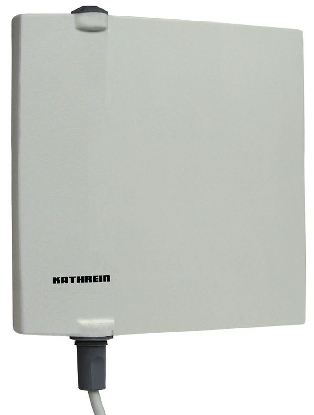
DVB-T/T2-Outdoor-Antenne
Merkmale
■ DVB-T/T2-Outdoor-Antenne für horizontale und vertikale Polarisa-
tion
■ Geeignet für DAB+
■ Aktive VHF-/UHF-Antenne mit integriertem Verstärker
■ Einfache Wand-, Mast- oder Balkonmontage
■ Ansprechendes und platzsparendes Design
■ Sehr niedrige Rauschzahl
■ Keine spezielle Ausrichtung erforderlich, da nahezu Rundstrahl-
Charakteristik (vertikal)
■ Fernspeisung (5 V/47 mA) erfolgt über das Koaxialkabel durch
den angeschlossenen DVB-T/T2-Empfänger oder mit externem
Fernspeise-Netzteil (5 – 25 V)
■ Anschluss: F-Buchse mit Wetterschutzkappe
Lieferumfang
● Wetterschutzkappe
● Befestigungsmaterial für Wand-, Mast- und Balkonmontage
● Anschlusskabel, 10 m inkl. F-Stecker und IEC-Stecker
Notwendiges Zubehör
Zum Empfang von DVB-T/T2-Signalen ist ein DVB-T/T2 geeigneter Empfänger mit Fernspeisemöglichkeit (5 V) über das Koaxialkabel
oder ein externes Fernspeise-Netzteil (5 – 25 V) notwendig.
Bestimmungsgemäßer Gebrauch
Die BZD 40 ist eine aktive Antenne zum Empfang von digitalen terrestrischen Ferhseh- und Rundfunksignalen im VHF- (Band III) und
UHF- (Band IV, V) Bereich. Sie ist zum Einsatz im Außenbereich mit ausreichendem Signalpegel geeignet.
Nur in Verbindung mit einem geeigneten DVB-T/T2-Empfänger mit Fernspeisemöglichkeit (5 V) über das Koaxialkabel oder mit einem
externen Fernspeise-Netzteil (5 – 25V) verwenden.
Jegliche anderweitige Nutzung oder die Nichtbeachtung dieses Anwendungshinweises und der den Geräten beiliegenden Dokumen-
tationen und Anleitungen hat den Verlust der Gewährleistung bzw. Garantie zur Folge.
Tipp Bewahren Sie die Anleitung für später auftretende Fragen sorgfältig auf und geben Sie diese bei einem Verkauf der
Antenne an den nächsten Besitzer weiter.
Allgemeines zum Rundfunkempfang
In Gebieten mit geringen oder zu starken Empfangsfeldstärken ist ein störungsfreier Empfang nicht in allen Fällen gewährleistet. Bei
zu schwachem Signalpegel ist es notwendig, eine Richtantenne mit Mastmontage außerhalb des Gebäudes zu verwenden.
In unmittelbarer Nähe zum Sender kann der Empfang durch zu hohe Empfangspegel beeinträchtigt werden.
Der Rundfunkempfang kann außerdem durch weitere Faktoren beeinträchtigt sein. Kritische Aufstellorte sind Räume in Stahlbeton-
bauten oder Gebäude mit metallbedampften Fenstern, geschlossene Metallschränke oder Aufstellorte in unmittelbarer Nähe von
sendenden, elektronischen Geräten (z. B. Mobiltelefonen).
1/6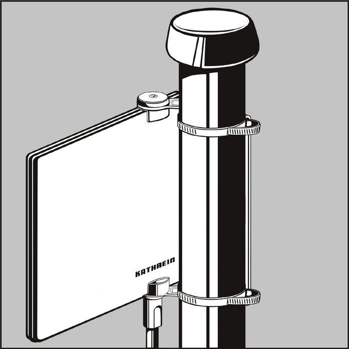
Sicherheitshinweise
          GEFAHR
          Lebensgefahr durch Stromschlag bei Berührung von elektrischen Einrichtungen!
          ► Bei Wandmontage vor dem Bohren der Löcher sicherstellen, dass keine elektrischen Leitungen in der Wand verlaufen.
          ► Auf Freileitungen achten, falls solche in der Nähe des Montageortes vorbeiführen.
          ► Niemals bei aufziehendem Gewitter oder während eines Gewitters an Antennenanlagen arbeiten.
          ► Erdungs- und Blitzschutzarbeiten wegen der Gefahr unzulänglicher Arbeitsergebnisse nur von hierfür speziell
            geschulten Fachkräften des Elektrohandwerks ausführen lassen.
          Lebensgefahr bei Montage/Betrieb in unsachgemäßen Umgebungsbedingungen!
          ► Dächer oder absturzgefährdete Stellen nur mit einem ordnungsgemäß angelegten intakten Sicherheitsgurt betreten.
          ► Sicherstellen, dass das Dach Ihr Gewicht aushält.
          ► Brüchige oder unstabile Flächen nicht betreten.
          ► Feste, rutschsichere Schuhe tragen.
          ► Sicherstellen, dass Leiter oder andere Aufstiegshilfen trocken, sauber und rutschsicher sind.
          ► Antennenmast nach DIN EN 60728-11 erden.
          VORSICHT
          Erstickungsgefahr durch verschluckte Teile!
          ► Montagezubehör von Kindern fernhalten.
          VORSICHT
          Gefahr schwerer Verletzungen durch herabfallende Teile!
          ► Wenn Passanten durch herabfallende Gegenstände während der Montage gefährdet werden können, den Gefahrenbe-
            reich absperren.
          ACHTUNG
          Gefahr von Sachschäden am Gerät durch unzulässige Versorgungsspannung!
          ► Antenne nur mit der zulässigen Spannung von 5 – 25 V betreiben.

Antenne aufstellen, anschließen und in Betrieb setzen
F-Stecker montieren
Verwenden Sie für die Montage ausschließlich die beiliegenden F-Stecker. Bei der Montage des F-Steckers keine Werkzeuge
verwenden, Stecker nur handfest anziehen.

          ACHTUNG
          Kurzschlussgefahr!
          Sachschaden durch die Berührung der Drähte des Abschirmgeflechtes mit dem Innenleiter.
          ► Sicherstellen, dass bei der Montage des F-Steckers kein Drähtchen des Abschirmgeflechtes den Innenleiter berührt.
          ► Sicherstellen, dass der Innenleiter nicht verbogen wird.

                                                                                                                   Kappe

1. Kappe auf das Kabel stecken.

1. 10 mm vom Außenkunststoffmantel ① entfernen. Dabei Außenkunststoffmantel
   vorsichtig einschneiden, um das Abschirmgeflecht ② nicht zu beschädigen.                                 ②③ ④
2. Abschirmgeflecht ② zurücklegen.
3. 7 mm Dielektrikum und Außenleiterfolie ③ vom Innenleiter ④ entfernen.
4. F-Stecker ⑤ auf das Kabelende aufdrehen, bis der Stecker fest auf dem Kabel sitzt.           ①                          ⑤

5. Sicherstellen, dass der Innenleiter max. 2 mm aus dem F-Stecker herausragt.

                                                                2/6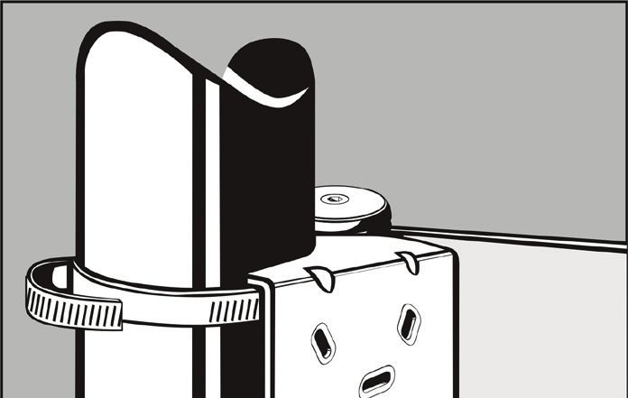
Antenne und Receiver anschließen
1. Die Antenne über das beiliegende Koaxialkabel mit dem DVB-T/T2-Receiver verbinden.

     Tipp      Die Antenne können Sie unabhängig von der Polarisation der abgestrahlten
               Signale montieren.

2. Den F-Stecker an der zugehörigen Buchse der Antenne festschrauben.
3. Die Kappe über den F-Stecker schieben, bis er im Antennengehäuse einrastet.
4. Den IEC-Stecker an der Rückseite des Receivers in die dafür vorgesehene Öffnung stecken.

5. Den Receiver mit dem TV-Gerät verbinden. Nähere Informationen der Anleitung des jeweiligen Receivers
   entnehmen.
6. Den Receiver einschalten.
7. Das TV-Gerät auf AV-Betrieb schalten, wenn das TV-Gerät sich nicht selbstständig umschaltet.
   ➯ Der Empfang von DVB-T/T2-Programmen ist möglich.

Empfang optimieren

  Tipp      Vor der Montage empfehlen wir Ihnen, Empfangsversuche für die geeignetste Position der Antenne zu machen, vorzugs-
            weise an den Stellen, an der Sie die Antenne später fest montieren werden. Beachten Sie dabei die Kabelverlegung.

Zur Verbesserung des Empfangssignals ist es möglich, die Antenne durch Schwenken auszurichten. Dazu:

1. Die Klemmschraube ① mit einem Innensechskant-Schlüssel SW4 lösen.                                      1

2. Die Antenne in 30º-Schritten schwenken, bis der Empfang gefunden ist.
3. Die Klemmschraube anziehen. Dabei darauf achten, dass das Halteblech im Antennenge-
   häuse einrastet.

     Tipp      Sollte kein optimaler Empfang möglich sein, testen Sie die Antenne an
               einem anderen Ort, welcher der Sendeantenne zugewandt ist und wieder-
               holen Sie die oben genannten Schritte.
               In unmittelbarer Nähe zum Sender kann der Empfang durch zu hohe
               Empfangspegel beeinträchtigt werden.

Empfang mit DVB-T/T2-Receiver optimieren
Einige Receiver bieten die Möglichkeit, den Empfangspegel und die Signalgüte auf dem Bildschirm anzuzeigen und erlauben somit
eine weitere Optimierung der Antennenaufstellung. Beachten Sie hierzu die Bedienungsanleitung des jeweiligen Receivers.

                                                               3/6
Sicherheitshinweise und allgemeine Hinweise
GEFAHR
Lebensgefahr durch Stromschlag bei Berührung von elektrischen Einrichtungen!
► Vor dem Bohren der Löcher sicherstellen, dass keine elektrischen Leitungen in der Wand verlaufen.
Bei Wand-, Mast- und Balkonmontage:
Achten Sie darauf, dass die Antenne so montiert wird, dass die Kappe und das Kabel nach unten zeigen. Damit wird
verhindert, dass Regentropfen über die Verschlusskappe ins Innere der Antenne gelangen können.
Ausnahme:
Nur wenn die Antenne vor Regen geschützt ist, ist eine waagerechte Anbringung erlaubt.
Wandmontage
Im Lieferumfang befindet sich das notwendige Befestigungsmaterial, um die Antenne an
der Wand zu befestigen.
1. Die optimale Empfangsposition der Antenne finden.
2. Die Löcher für die Wandhalterung bohren.
3. Die Antenne an der Wand montieren.
Mastmontage
Im Lieferumfang befindet sich das notwendige Befestigungsmaterial, um die Antenne an
einem Mast zu befestigen.
1. Die zwei mitgelieferten Schneckengewinde-Schlauchschellen an den Mast schrauben.
Dabei die Schrauben noch nicht ganz festziehen.
2. Der Haltewinkel der BZD 40 besitzt an der oberen und unteren Kante einen Befesti-
gungszapfen. Diesen jeweils in eine Schlauchschelle einhängen.
3. Die Antenne drehen, um die optimale Empfangsposition der Antenne zu ermitteln.
4. Die Schneckengewinde-Schlauchschelle und die Klemmschraube festziehen.
4/6Balkonmontage
Im Lieferumfang befindet sich das notwendige Befestigungsmaterial, um die Antenne an
einem Balkon zu befestigen.
1. Die optimale Empfangsposition der Antenne finden.
2. Die Löcher für die Balkonhalterung bohren.
3. Die Antenne an dem Balkon montieren.
Optionale Montagelage
Die Montagepositionen der Antenne können durch Umbau des Haltewinkels geändert werden:
Auslieferungszustand Umbauzustand
1
Um den Haltewinkel umzubauen:
1. Die Klemmschraube ① und gegebenenfalls die Kappe und das Kabel ➁ entfernen.
2. Den Haltewinkel ausbauen.
3. Den Haltewinkel drehen (oben und unten vertauschen).
4. Den Haltewinkel einbauen. Dabei darauf achten, dass der Haltewinkel zuerst unten
eingefädelt wird.
5. Den Haltewinkel mittels der Klemmschraube wieder befestigen.
2
Antennenkabel durch die Wand verlegen
Um das Kabel durch die Wand nach außen zu verlegen (nach erfolgreicher F-Stecker- und Antennenmontage):
1. Den F-Stecker demontieren.
2. Die Verschlusskappe vom Kabel abnehmen.
3. Das Kabel von innen durch das Loch in der Wand nach außen führen.
4. Außen die Verschlusskappe wieder auf das Kabel stecken.
5. Den F-Stecker wieder auf das Kabel schrauben.
5/6Falsche Montagesituation
Bei Wand-, Mast- und Balkonmontage:
Achten Sie darauf, dass die Antenne so montiert wird, dass die Kappe und das Kabel
nach unten zeigen. Damit wird verhindert, dass Regentropfen über die Verschluss-
kappe ins Innere der Antenne gelangen können.
Ausnahme:
Nur wenn die Antenne vor Regen geschützt ist, ist eine waagerechte Anbringung
erlaubt.
Reinigung
● Die Antenne nur mit einem leicht angefeuchteten Tuch reinigen.
● Keine aggressiven oder scheuernden Reinigungsmittel verwenden, da diese die Gehäuseoberfläche beschädigen können.
● Das Gerät niemals in Flüssigkeiten tauchen.
Technische Daten
Typ BZD 40
Bestell-Nr. 20710005
Empfangsbereich VHF/UHF MHz 174 – 230/470 – 790
Güte ¹ )
dB/K typ. -32
Spannbereich des Befestigungsbandes mm 9, ø 40 – 48
Max. Ausgangspegel ²) dBµV typ. 95
Abmessungen (mit Halter) mm 204 x 196 x 71
Windlast bei 800 N/m N 39
Verpackungseinheit/Gewicht St./kg 1 (10)/1,1
Maße der Einzelverpackung mm 210 x 250 x 75
¹) In Bereichsmitte, bei 8 MHz Bandbreite und Tu = 290 K
²) Nach EN 60728-5 für 60 dB (2 Sender - 3. Ordnung) gemessen am Antennenausgang
Entsorgung
Elektronische Geräte
Elektronische Geräte gehören nicht in den Hausmüll, sondern müssen gemäß Richtlinie 2012/19/EU DES EUROPÄISCHEN PAR-
LAMENTS UND DES RATES vom 4. Juli 2012 über Elektro- und Elektronik-Altgeräte fachgerecht entsorgt werden. Bitte geben Sie
dieses Gerät am Ende seiner Verwendung zur Entsorgung an den dafür vorgesehenen öffentlichen Sammelstellen ab.
www.kathrein-ds.com | support@kathrein-ds.com 9363652/d/STM/0521/DE | Änderungen vorbehalten.
KATHREIN Digital Systems GmbH | Anton-Kathrein-Str. 1–3 | 83022 Rosenheim | Deutschland | Telefon +49 731 270 909 70BZD 40 20710005
suitable for DVB-T/T2
DVB-T/T2 Outdoor Antenna
Features
■ DVB-T/T2 outdoor antenna for horizontal and vertical polarisation
■ Suitable for DAB+
■ Active VHF/UHF antenna with integrated amplifier
■ Easy wall, mast or balcony mounting
■ Active, space-saving design
■ Very low noise factor
■ No special alignment necessary due to a nearly round emission
characteristic (vertical)
■ Remote power feed (5 V/47 mA) via the coaxial cable by means
of the connected DVB-T/T2 receiving device or external remote
power supply unit (5 – 25 V)
■ Connection: F-type socket with weather shield cap
Scope of Delivery
● Weather shield cap
● Mounting material for wall, mast and balcony mounting
● Connection cable, 10 m incl. F-type connector and IEC connector
Necessary Accessories
For the reception of DVB-T/T2 signals, a DVB-T/T2-compatible receiving device with remote power feed (5 V) via the coaxial cable or an
external remote power supply unit (5 – 25 V) is required.
Intended Use
The BZD 40 is an active antenna for the reception of digital terrestrial television and radio signals in the VHF- (Band III) and UHF
(Band IV, V) bands. The antenna is suitable for the outdoor use when the signal level is sufficiently high.
Only use together with a suitable DVB-T/T2 receiving device with remote power feed (5 V) via the coaxial cable or an external remote
feed power supply unit (5 – 25 V).
Any other use or failure to comply with these user instructions and the documentation and instructions accompanying the equip-
ment will void the warranty or guarantee.
Tip Keep these instructions for further reference and give them to the next owner if the antenna is sold.
General Remarks on Broadcasting
In areas with low or too high reception-field strength, interference-free reception is not always guaranteed. If the signal level is too
low, it is necessary to place a directional antenna outside the building.
In the immediate vicinity of the transmitter, reception may be impaired by too high a reception level.
Reception indoors can also be impaired by other factors. Critical locations are rooms in reinforced concrete buildings or buildings
with vapour-plated windows, closed metal cabinets, or positions directly beside transmitting electronic devices, e.g. mobile phones.
1/6Safety Instructions
DANGER
Danger to life from electric shock when touching electrical installations!
► Wall mounting: before drilling holes, make sure that there is no electrical wiring in the wall.
► Pay attention to exposed wires if they are situated close to the installation location.
► Never work on antenna systems when a storm is approaching or during a storm.
► Make sure that earthing and lightning protection measures are carried out by a specially trained electrician.
Danger to life during installation/operating in improper ambient conditions!
► Wear a properly fitted and intact safety harness when working on a roof or in any other location where you are at risk of
falling.
► Make sure that the roof is able to carry your weight.
► Do not enter crumbling or unstable surfaces.
► Wear stable shoes with non-slip soles.
► Make sure that the roof and climbing aid are dry, clean and non-slip.
► Make sure that the antenna mast is earthed in accordance with DIN EN 60728-11.
CAUTION
Risk of suffocation due to small parts that could be swallowed!
► Keep any mounting material out of reach of children.
CAUTION
Risk of severe injuries from falling parts!
► If passers-by are at risk due to falling parts during installation, the area of risks must be cordoned off.
NOTICE
Risk of material damage due to incorrect supply voltage!
► Operate the antenna only at the permitted voltage of 5 – 25 V.
Setting up, Connecting and Commissioning
Attaching F-type Connector
Only use the enclosed F-type connectors. Do not use any tools to attach the F-type connectors, tighten them hand-tight.
NOTICE
Risk of short circuit!
Material damage due to contact between the wires of the braided shield and the inner conductor.
► When attaching the F-type connectors, make sure that there is no contact between the wires of the braided shield and
the inner conductor.
► Make sure that the inner conductor is not bent.
Cap
1. Put the weather shield cap onto the cable.
1. Remove 10 mm from the outer plastic jacket ①. Cut into it carefully not to damage the
braided shield ②. ②③ ④
2. Put the braided shield ② back.
3. Remove 7 mm dielectric and aluminium foil ③ from the inner conductor ④.
4. Screw the F-type connector ⑤ onto the end of the cable until it sits tightly. ① ⑤
5. Make sure that the inner conductor is exposed 2 mm max..
2/6Connecting the Antenna and the Receiver
1. Connect the antenna to the DVB-T/T2 receiver using the coaxial cable provided.
Tip You can set up the antenna independently from the polarisation of the radiated
signals.
2. Screw the F-type connector onto the matching antenna socket.
3. Push the cap over the F-type connector until it sits tightly in the antenna housing.
4. Plug the IEC connector on the rear of the receiver into the corresponding socket.
5. Connect the receiver with the TV set. For more information about the connection, refer to the operating
manual of your receiver.
6. Turn on the receiver.
7. Switch the TV to the AV mode if the TV set does not switch to it automatically.
➯ The reception of DVB-T/T2 programmes is possible.
Optimising the Reception
Tip Before installing the antenna, we recommend to test the reception and look for the most suitable reception location, pref-
erably where you are going to mount the antenna later. Pay attention to how the cables are going to be run.
To improve the reception signal, it is possible to align the antenna by swivelling it. In order to do so:
1. Release the clamp screw ① using an allen key SW4. 1
2. Swivel the antenna in 30º increments until the reception is satisfactory.
3. Tighten the clamp screw. Make sure that the retaining plate sits tightly in the antenna
housing.
Tip If it is impossible to get optimum reception, test the antenna at a different loca-
tion facing towards the transmitting antenna and repeat the steps described
above.
In the immediate vicinity of the transmitter, reception might be impaired by too
high a reception level.
Optimising the Reception with a DVB-T/T2 Receiver
Some receivers offer the option of displaying the reception level and the signal quality on the screen, thus permitting further optimi-
sation of the antenna set-up. For more information, refer to the operating manual of your receiver.
3/6Safety Instructions and general Notes
DANGER
Danger to life from electric shock when touching electrical installations!
► Before drilling holes, make sure that there is no electrical wiring in the wall.
For wall, mast and balcony mounting:
Make sure that the antenna is mounted such that the cap and the cable face downwards. This prevents rain from drip-
ping inside the antenna through the cap.
Exception:
Only if the antenna is protected from the rain, the horizontal mounting is permitted.
Wall Mounting
The necessary mounting material for mounting the antenna on a wall is included in the
scope of delivery.
1. Find the optimum reception position for the antenna.
2. Drill the holes for the wall bracket.
3. Mount the antenna on the wall.
Mast Mounting
The necessary mounting material for mounting the antenna on a mast is included in the
scope of delivery.
1. Attach the two supplied worm drive hose clips to the mast. Make sure not to tighten
the bolts fully.
2. The mounting bracket of the BZD 40 has lugs at the top and at the bottom. Engage
them in the two hose clips.
3. Rotate the antenna to obtain the optimum reception.
4. Tighten the worm drive hose clips and the clamp screw.
4/6Balcony Mounting
The necessary mounting material for mounting the antenna on a balcony is included in the
scope of delivery.
1. Find the optimum reception position for the antenna.
2. Drill the holes for the balcony mounting bracket.
3. Mount the antenna on the balcony.
Optional Mounting Position
The range of possible mounting positions of the antenna can be extended by modifying the mounting bracket:
Shipping condition Condition after modification
1
In order to modify the mounting bracket:
1. Remove the clamp screw ① and, if necessary, the cap and the cable ➁.
2. Remove the bracket.
3. Turn the bracket over (interchange the top and bottom).
4. Mount the bracket. Make sure to slot it in at the bottom first.
5. Fix the mounting bracket with the clamp screw.
2
Running the Antenna Cable through the Wall
To run the cable through the wall to the outside (after attaching the F-type connector and mounting the antenna):
1. Remove the F-type connector from the cable.
2. Remove the weather shield cap from the cable.
3. Run the cable outside through the hole in the wall from the inside.
4. Outside, put the weather shield cap back on the cable.
5. Screw the F-type connector onto the cable.
5/6Incorrect Mounting
For wall, mast and balcony mounting:
Make sure that the antenna is mounted such that the cap and the cable face down-
wards. This prevents rain from dripping inside the antenna through the cap.
Exception:
Only if the antenna is protected from the rain, the horizontal mounting is permitted.
Cleaning
● Clean the antenna only with a slightly moistened cloth.
● Do not use aggressive or abrasive cleaners because these could damage the surface of the housing.
● Do not immerse the device in any fluid.
Technical Data
Typ BZD 40
Order number 20710005
Reception range VHF/UHF MHz 174 – 230/470 – 790
Quality ¹)
dB/K typ. -32
Clamping range of the worm drive hose clip mm 9, ø 40 – 48
Max. output level ²) dBµV typ. 95
Dimensions (with holder) mm 204 x 196 x 71
Wind load at 800 N/m N 39
Packaging unit/weight pc./kg 1 (10)/1.1
Single pack dimensions mm 210 x 250 x 75
1) In mid-range, at 8 MHz bandwidth and Tu = 290 K
2) According to EN 60728-5 for 60 dB (2 senders – 3rd order) measured at antenna output
Waste Disposal
Electronic equipment
Electronic equipment is not domestic waste – in accordance with directive 2012/19/EC OF THE EUROPEAN PARLIAMENT AND
THE COUNCIL dated 04th July 2012 concerning used electrical and electronic appliances, it must be disposed of properly. At
the end of its service life, take this unit for disposal at a designated public collection point.
www.kathrein-ds.com | support@kathrein-ds.com 9363652/d/STM/0521/GB | Subject to change.
KATHREIN Digital Systems GmbH | Anton-Kathrein-Str. 1–3 | 83022 Rosenheim | Germany | Phone +49 731 270 909 70Sie können auch lesen