INSTALLATIONSANLEITUNG EPOLEDUO FÜR EBOX SMART, PROFESSIONAL UND TOUCH EPOLEDUO INSTALLATION INSTRUCTIONS FOR EBOX SMART, PROFESSIONAL AND TOUCH
←
→
Transkription von Seiteninhalten
Wenn Ihr Browser die Seite nicht korrekt rendert, bitte, lesen Sie den Inhalt der Seite unten
Installationsanleitung ePoleDuo
für eBox smart,
professional und touch
ePoleDuo installation instructions
for eBox smart,
professional and touch
2 Installationsanleitung ePoleDuo
Inhalt

Inhalt
04   Sicherheitshinweise
     Qualifikation für elektrotechnische Arbeiten 5

06   Produktübersicht
     Lieferumfang 6
     ePoleDuo – die Produktdetails   7
     Technische Daten 7

08   Installation
                                                      Instructions
                                                        in English
     Vor der Installation 8                            See pages 21 ff.
     Leitungswahl 8
     Die Wahl des Standortes 10
     Betonfundament 10
     Benötigtes Werkzeug 11
     Zuleitungen 11
     Montage 12

15   Nächste Schritte
     Demontage 17
     Entsorgung 17

     Impressum 19
4 Installationsanleitung ePoleDuo
Sicherheitshinweise
GEFAHR
Gefahr für Leib und Leben
Warnung vor elektrischer Spannung!
ACHTUNG
Erhebliche Verletzungsgefahr/Materialschaden
Achtung, es besteht das Risiko einer erheblichen Verletzung oder eines Materialschadens!
HINWEIS
Hinweis zur Optimierung der Anwendung
Durch Befolgen des Hinweises kann die Anwendung des Produktes verbessert werden.
Diese Installationsanleitung richtet sich • Bitte lesen Sie die mitgelieferte (RCD-Schutz) und Leitungsschutz
an Elektrofachkräfte. Die Installation Dokumentation, damit Sie sich mit schalter (LS), wie nachfolgend in
der ePoleDuo muss durch qualifizierte den Sicherheitsvorschriften und diesem Dokument beschrieben,
Elektrofachkräfte erfolgen. Überge Hinweisen vertraut machen, bevor installiert ist.
ordnet gilt es, die allgemeinen Unfall Sie dieses Produkt installieren und •R CD und LS sind gemäß elektrischem
verhütungsvorschriften sowie die verwenden. Anschluss auszuwählen und in einem
länder- und betriebsspezifischen • Dieses Produkt wurde in Überein vorgelagerten Sicherungskasten zu
sicherheitstechnischen Regeln und stimmung mit internationalen installieren.
arbeitsmedizinischen Bestimmungen Standards entwickelt und geprüft. • Stellen Sie sicher, dass das Wartungs
zu beachten. • Dieses Produkt darf ausschließlich intervall des eingesetzten RCDs gemäß
Nur durch Befolgen dieses Doku für den Bestimmungszweck ver Herstellerangabe eingehalten wird.
mentes kann später eine störungs wendet werden.
freie Inbetriebnahme des Produktes • Dieses Produkt darf nur durch quali Vor der Installation sind die Vorgaben
sichergestellt werden. Diese Installa fiziertes Personal installiert werden. der Netzanschlussverordnung
tionsanleitung ist Bestandteil des •D ieses Produkt ist wartungsfrei und (NAV), der Technischen Anschluss-
Produktes und muss den Installateuren kann nicht vor Ort repariert werden. bedingungen (TAB) und solche des
auch nach der Installation zur Ver • Inkorrekte Installation kann Gefahren zuständigen Netzbetreibers zu
fügung stehen. Bewahren Sie dieses für den Benutzer zur Folge haben. prüfen und insbesondere Anmelde-,
Dokument daher auch über die Instal •D ieses Produkt wird in Kombination Genehmigungs- und Verzeichnis-
lation hinaus gut auf. mit einer Stromquelle verwendet. pflichten zu beachten.
Beachten Sie des Weiteren, dass •S tellen Sie sicher, dass das Produkt Technische Änderungen des
Sicherheit nur dann gewährleistet ist, nur unter korrekten Betriebsbedin Produktes vorbehalten. Technische
wenn die betroffenen Geräte sach gungen verwendet wird. Änderungen und Änderungen von
gemäß, wie nachfolgend in diesem •S tellen Sie sicher, dass die Strom Daten oder beschriebenen Abläufen
Dokument beschrieben, gelagert, ins versorgung dieses Produktes sach können ohne Ankündigung und
talliert, verwendet, gewartet und ggf. gerecht an einem Sicherungskasten Aktualisierung des vorliegenden
demontiert und entsorgt werden. mit Fehlerstromschutzschalter Dokumentes auftreten.Sicherheitshinweise 5
Qualifikation für elektrotechnische Arbeiten
Die Fachkraft, die die elektrische Installation und Wartung des Gerätes Gefahr
vornimmt oder beaufsichtigt, muss diese Installationsanleitung gelesen haben Die unsachgemäße Handhabung
und deren Anweisungen befolgen. Außerdem muss sie vom Anlagenbetreiber spannungsführender Kompo
nenten kann zu schweren Ver
beauftragt worden sein.
letzungen mit tödlichen Folgen
führen. Achten Sie daher stets
auf die fünf Sicherheitsregeln
Deutschland aus DIN VDE 0105:
• Freischalten
• Gegen Wiedereinschalten sichern
Es gelten die Anforderungen aus DGUV Vorschrift 3 bzw. DIN VDE 0105-100: • Spannungsfreiheit feststellen
(allpolig)
• Fachliche Ausbildung (Elektrotechnik) • Erden und kurzschließen
• Benachbarte, unter Spannung
• Kenntnisse und Erfahrungen im jeweiligen Tätigkeitsfeld stehende Teile abdecken oder
• Kenntnisse der einschlägigen Normen abschranken
• Beurteilung der ihr übertragenen Arbeiten
• Erkennen von Gefahren
Österreich
Es gelten die Anforderungen aus ÖVE/ÖNORM EN 50110-1: Achtung
Kleinteile für Kinder gefärlich.
Nicht in Gegenwart von Kindern
Als Elektrofachkraft gilt „eine Person mit geeigneter fachlicher Ausbildung, installieren.
Kenntnissen und Erfahrung, so dass sie Gefahren erkennen und vermeiden
kann, die von der Elektrizität ausgehen können.“
Schweiz
Achtung
Es gelten die Anforderungen aus NIV, SR 734.27: Stellen Sie sicher, dass sämtliche
Komponenten während der ge
„2. Kapitel: Bewilligung für Installationsarbeiten, 1. Abschnitt: Bewilligungs samten Installation trocken sind.
pflicht, Art. 6
Wer elektrische Installationen erstellt, ändert oder in Stand stellt und wer
elektrische Erzeugnisse an elektrische Installationen fest anschliesst oder
solche Anschlüsse unterbricht, ändert oder in Stand stellt, braucht eine
Installationsbewilligung des Inspektorates.
2. Abschnitt: Allgemeine Installationsbewilligung, Art. 7 – Bewilligung für
natürliche Personen
Natürliche Personen, die in eigener Verantwortung Installationsarbeiten
ausführen, erhalten die allgemeine Installationsbewilligung, wenn:
a) sie fachkundig sind;
b) ihr Ausbildungsstand dem neuesten Stand der Technik entspricht
und ihre Weiterbildung gewährleistet ist; und
c) s ie Gewähr bieten, dass sie die Vorschriften dieser Verordnung einhalten.“6 Installationsanleitung ePoleDuo
Produktübersicht
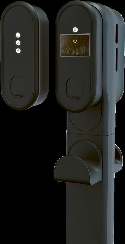
Die ePoleDuo dient als Montagestele
für zwei eBoxen mit zwei eClicks.
Das modulare Konzept des Gesamt eBox
produkts ermöglicht auch eine eClick
separate Installation der ePoleDuo
im Voraus.
eClick
eBox
ePoleDuo
Lieferumfang Folgende Produkte können
separat bestellt werden:
• Kabelhalterung
1 Alu-Kopf mit 1 Schloss • Betonfundament
1 Alu-Säule • Fehlerstromschutzschalter (RCD)
1 Bodenplatte • Leitungsschutzschalter
2 Abdeckplatten für Alu-Kopf
Montagematerial
4 Schrauben für die Bodenplatte
4 Schrauben mit 4 Unterlegscheiben
für den Alu-Kopf
4 M16 Muttern mit 4 Unterlegscheiben
mit 4 Kappen
Hinweis: Zur Montage der
eBoxen an der ePoleDuo
benötigten Sie zwei eClicks,
diese sind nicht Bestandteil
der ePoleDuo.
Achtung
Der Inhalt der Lieferung ist auf Vollständigkeit
und Unversehrtheit zu prüfen.Produktübersicht 7
ePoleDuo – die Produktdetails
01
Alu-Kopf
02
1 Abdeckplatte für Alu-Kopf
2
03
Schloss
3
5
2 04
Alu-Säule
05
Kabelhalterung (optional, exklusive)
5
06
Bodenplatte
4
07
Betonfundament (optional, exklusive)
6
7
Technische Daten
Maße H x B x T 1.608 mm x 208 mm x 175 mm (ohne Kabelhalter)
1.608 mm x 208 mm x 427 mm (mit zwei Kabelhaltern)
Maße kurze Variante H x B x T 1.280 mm x208 mm x 175 mm (ohne Kabelhalter)
1.280 mm x 208 mm x 427 mm (mit zwei Kabelhaltern)
Montageart Freistehend auf Betonfundament
Gewicht 19,3 kg (kurze Variante 17,0 kg), Kabelhalter 1,5 kg
Schutzart IP55 (mit eBox oder Abdeckhaube auf eClick)
Betriebstemperatur -30 °C bis +50 °C8 Installationsanleitung ePoleDuo
Installation
Dieses Kapitel ist unterteilt in Vorbereitung vor der
Installation, Zuleitungen, Montage und nächste Schritte.
Gefahr Achtung
Machen Sie sich vor der Jede eClick muss jeweils mit einem
Installation mit den Fehlerstromschutzschalter und
Sicherheitshinweisen vertraut. einem Leitungsschutzschalter im
Verteilerkasten gesichert werden.
Stimmen Sie sich vorher mit dem
Kunden über die gewünschte
Ausgangsleistung ab und ver
wenden Sie die zur Stromstärke
passenden Schutzkomponenten
(Tabelle Y).
Vor der Installation
Prüfen Sie und stellen Sie sicher, dass die für den Anschluss In den jeweiligen Stromkreisen dürfen keine weiteren
vorgesehene Elektroinstallation die erforderliche elektrische elektrischen Geräte eingebunden werden.
Leistung liefern kann.
Stimmen Sie sich vor der Installation mit dem Eigentümer
Jede eClick muss jeweils entsprechend der jeweiligen oder Betreiber der Anlage über die gewünschte Aus
Zuleitung mit einem FI/RCD (Fehlerstromschutzschalter) gangsleistung ab und verwenden Sie die dazu passenden
und einem LS (Leitungsschutzschalter) in der Vorinstallation Schutzkomponenten.
abgesichert werden.
Leitungswahl
Bei der Leitungswahl sind die gültigen, internationalen, län Der Kabelquerschnitt ist so auszuwählen, dass die Eigener
derspezifischen und regionalen Vorschriften und Normen wärmung auf 15K begrenzt wird.
einzuhalten. Bei der Leitungswahl ist der Anschluss an einen
Dreiphasen-Drehstromkreis oder einen Einphasen-Wechsel
stromkreis entsprechend entpsrechend der Vorschriften
und Normen zu berücksichtigen.Installation 9
Fehlerstromschutzschalter Variante 1 Variante 2
Ladeleistung 3,7 kW; 11 kW 7,4 kW; 22 kW
Ladestrom 16 A 32 A
Beispiel F204A, 4-polig, 25/0,03 A ABB F204 A, 4-polig, 40/0,03 A ABB
Normen DIN EN 61008-1/DIN EN 61008-2-1 DIN EN 61008-1/DIN EN 61008-2-1
Typ A A
Betriebsspannung 230/400 V AC 230/400 V AC
Pole Vierpolig Vierpolig
Bemessungsfehlerstrom 30 mA 30 mA
Bemessungsstrom 25 A 40 A
Auslösezeit 300 ms 300 ms
Betriebskennlinie kurzzeitverzögert (AP-R)
Überspannungskategorie III III
Verschmutzungsgrad 2 2
Tmax +55 °C, Tmax +55 °C,
Umgebungstemperatur
Tmin -25 °C Tmin -25 °C
Materialnummer 10284822 10118695
Leitungsschutzschalter Variante 1 Variante 2
Ladeleistung 3,7 kW; 11 kW 7,4 kW; 22 kW
Ladestrom 16 A 32 A
Beispiel S203-NA K, 20A ABB S203-NA K, 40A ABB
Normen DIN EN 60947-1, -2/DIN EN 60898-1 DIN EN 60947-1, -2/DIN EN 60898-1
Auslösecharakteristik K K
Pole Vierpolig Vierpolig
Bemessungsschaltvermögen 6.000 A 6.000 A
Bemessungsstrom 20 A 40 A
Isolationsspannung 4 kV 4 kV
Überspannungskategorie III III
Verschmutzungsgrad 2 2
Tmax +55 °C, Tmax +55 °C,
Umgebungstemperatur
Tmin -25 °C Tmin -25 °C
Materialnummer 10133671 10118694
• Installation der Überspannungsschutzeinrichtung,
sofern in nationalen Normen gefordert
• Verlegung der Anschlussleitung zum Installationsort
Achtung
• Anschluss der Zuleitung zur eClick/eBox an die Aus Platzgründen ist nach
Unterverteilung Möglichkeit eine Zuleitung
mit ≤ 6 mm² Kabelquerschnitt
auszuwählen.10 Installationsanleitung ePoleDuo
Die Wahl des Standortes
Der Standort der ePoleDuo ist in der Regel bei der Vor Gefahr
ortbegehung im Vorfeld der Installation mit dem Kunden Das Gerät darf nicht in einem
vereinbart worden. explosionsgefährdeten Bereich
installiert werden.
Für einen reibungslosen Installationsablauf müssen die
folgenden Vorbereitungen getroffen werden.
Betonfundament
Die ePoleDuo muss auf einem Betonfundament installiert
werden.
Betonfundament setzen
Das passende Betonfundament kann bei innogy bestellt
werden (Materialnummer 10122614). Dieses Betonfunda
ment besitzt vier Gewindestangen. Die ePoleDuo wird
mittels der im Lieferumfang befindlichen Bodenplatte auf
das Betonfundament montiert.
Richtung des
LadepunktsInstallation 11
Benötigtes Werkzeug
Zur Montage der ePoleDuo wird
folgendes Werkzeug benötigt:
• Innensechskantschlüssel 5 mm
• Kabelbinder
Maulschlüssel
• Maulschlüssel 24 mm
• Wasserwaage
• (Akku-)Bohrmaschine
Innensechskantschlüssel
5 mm
Zuleitungen
Da jede eClick mit einem separaten Fehlerstromschutz
schalter und einem Leitungsschutzschalter in der Unter
verteilung versehen werden muss, ist es notwendig, zwei
elektrische Zuleitungen durch die ePoleDuo zu führen.
Gefahr
Es besteht die Gefahr eines
elektrischen Stromschlags!
2 Zuleitungen
Gefahr
Vergewissern Sie sich, dass
die Sicherung der Stromkreise
ausgeschaltet und die verwen
deten Komponenten spannungs
frei sind.12 Installationsanleitung ePoleDuo
Führen Sie die beiden elektrischen Zuleitungen zum
Installationsort. Halten Sie jeweils mindestens 2.000 mm
Kabellänge am Installationspunkt bereit, um die Zuleitungen
später jeweils durch die ePoleDuo zu führen und die
eClicks anschließen zu können.
Sollen die beiden eBoxen per LAN angeschlossen werden,
müssen analog zwei Ethernetkabel verlegt werden.
Gefahr
Achten Sie darauf, dass die
elektrischen Zuleitungen
während der ganzen Installation
spannungsfrei sind.
Kabellänge
mindestens 2.000 mm
Montage
Verschaffen Sie sich vor der Montage der ePoleDuo einen
Überblick über die nötigen Schritte.Installation 13
01
Führen Sie die elektrische Zuleitung
und ggf. Ethernetkabel durch das
Betonfundament. Es sollten Ihnen
nun oben noch mindestens zwei Meter
je Zuleitung zur Verfügung stehen.
02
Setzen Sie die Alu-Säule auf die Boden
platte und verschrauben Sie diese mit
den vier mitgelieferten Schrauben.
Dieser Schritt muss erfolgen, bevor die
Bodenplatte auf dem Betonfundament
verschraubt wird.
03
Setzen Sie die zusammengeschraubte
Bodenplatte mit Alu-Säule auf das
Achtung
Betonfundament und verschrauben Ziehen Sie die Muttern
Sie die Bodenplatte mit den Gewinde mit einem Drehmoment
stangen des Betonfundaments mithilfe von mindestens 35 Nm an.
der mitgelieferten Unterlegscheiben,
Muttern und Kappen.
04
Befestigen Sie die elektrischen
Zuleitungen sowie ggf. die Ethernetkabel
zwischenzeitlich mit Kabelbindern am
oberen Ende der Alu-Säule.14 Installationsanleitung ePoleDuo
05
Wenn Sie Kabelhalter installieren
möchten, montieren Sie diese nun
gemäß der Schritte 05.01 bis 05.04
an der Alu-Säule. Springen Sie an
sonsten zu Punkt 6.
05.03
Ziehen Sie die Schrauben mithilfe
eines Innensechskantschlüssels fest,
während Sie die Aufhängungen mit
einem Maulschlüssel fixieren.
05.01
Drücken Sie beidseitig die jeweils
zwei Einsätze am oberen Ende der
Alu-Säule von innen heraus.
05.04
Setzen Sie die Kabelhalterung auf die
Aufhänger auf und fixieren Sie sie mit
dem beigelegten Metallstück und der
Schraube an der Alu-Säule.
05.02
Schieben Sie die mit den Kabelhaltern
mitgelieferten Schrauben durch die
Aufhängungen und drehen Sie sie
locker in die Spreizdübel ein. Setzen
Sie die Aufhängungssysteme danach
in die Löcher ein.
06
Bevor Sie den Alu-Kopf auf die
Säule setzen, bohren Sie mit der
Akku-Bohrmaschine an den vier
Löchern vor. Setzen Sie den Alu-
Kopf auf und führen Sie dabei
eine Zuleitung je Seite (elektrisch
und ggf. Ethernetkabel) durch den
Alu-Kopf.
07
Abschließend verschrauben Sie den
Alu-Kopf mit den vier beigelegten
Unterlegscheiben und Schrauben
fest mit der Alu-Säule.Nächste Schritte 15
Nächste Schritte
Nach der Montage der ePoleDuo können:
• eClicks und eBoxen sofort oder
• eClicks sofort und eBoxen später oder
• eClicks und eBoxen später installiert werden.
A) eClicks und eBoxen sofort installieren
Sind die eClicks und eBoxen verfügbar, so installieren Sie Gefahr
Es besteht die Gefahr eines
diese sofort.
elektrischen Stromschlags!
01
Die eClicks können gemäß
02
Klicken Sie die beiden
03
Setzen Sie auf beiden
der beiliegenden Installa eBoxen ein. Seiten die Abdeckplatten
tionsanleitung eClick der ePoleDuo unterhalb
installiert werden. der eBoxen auf den Alu-
Kopf.16 Installationsanleitung ePoleDuo
04
Verschließen Sie das
05
Händigen Sie den Schlüssel
06
Nehmen Sie die eBoxen
Schloss, sodass die beiden dem Eigentümer oder Be gemäß der beiliegenden
Abdeckplatten verschlossen treiber der ePoleDuo aus. Installationsanleitung in
werden. Betrieb.
Der Hebel der eClicks zum
Lösen der eBoxen ist nun
nicht mehr zugänglich.
B) eClicks und eBoxen später installieren
Sind keine eClicks verfügbar, stellen Sie dauerhafte Gefahr
Es besteht die Gefahr eines
Spannungsfreiheit der Zuleitungen sicher.
elektrischen Stromschlags!
01
Sind noch keine eClicks
02
Händigen Sie den Schlüssel
03
Lassen Sie die elektrische
vorhanden, so fixieren Sie dem Eigentümer oder Zuleitung spannungsfrei,
die Zuleitungen so, dass sie Betreiber der ePoleDuo aus. sodass die Zuleitungen
für eine spätere Installation nicht mit Spannung ver
der eClicks leicht zugänglich sorgt werden!
sind.Nächste Schritte 17
Demontage
Die Demontage der eClicks muss von einer Elektrofach Sobald Sie die eClicks und die eBoxen gemäß Installa
kraft durchgeführt werden. tionsanleitung eClick demontiert haben, können Sie den
Alu-Kopf abschrauben und anschließend die Alu-Säule
Für die Demontage der ePoleDuo schalten Sie zunächst abnehmen. Schrauben Sie den Stahl-Montageträger
die beiden eBoxen und eClicks spannungsfrei. Lassen Sie vom Betonfundament ab.
die Zuleitungen während der ganzen Zeit der Demontage
spannungsfrei. Stellen Sie sicher, dass die elektrischen Zuleitungen auch
nach der Demontage der ePoleDuo spannungsfrei sind.
Die Demontage der eClick und der eBoxen ist in der
Installationsanleitung der eClick beschrieben.
Entsorgung
Bitte entsorgen Sie die Aluminium- und Stahlteile
fachgerecht.18 Installationsanleitung ePoleDuo
Impressum   19

Impressum

Urheberrecht und Copyright 2020 innogy eMobility Solutions GmbH.
Alle Rechte vorbehalten. Dieses Dokument ist geschützt vom
Urheberrecht und vom Copyright. Es darf nicht ohne schriftliches
Einverständnis der innogy eMobility Solutions GmbH verändert,
vervielfältigt oder in sonstiger Weise ganz oder teilweise außer
zum Zwecke der ordnungsgemäßen Installation der ePoleDuo zum
Zwecke der Veröffentlichung verwendet werden.

© innogy eMobility Solutions GmbH
Flamingoweg 1
44139 Dortmund
Deutschland

Sitz der Gesellschaft: Dortmund
Eingetragen beim Amtsgericht Dortmund,
Handelsregister-Nr. HRB 30359
20
21

ePoleDuo installation instructions
for eBox smart,
professional and touch
22 ePoleDuo installation instructions
Contents   23

Contents
24   Safety information
     Qualifications for electrical work 25

26   Product overview
     Included in delivery 26
     ePoleDuo – the product details 27
     Specifications 27

28   Installation
     Before installing 28
     Line selection 28
     Choosing the site 30
     Concrete foundation 30
     Tools needed 31
     Supply lines 31
     Mounting 32

35   Next steps
     Dismounting 37
     Disposal 37

     Legal notice   39
24 ePoleDuo installation instructions
Safety information
DANGER
Danger to life and limb
Warning of electrical voltage!
CAUTION
Significant risk of injury/material damage
Caution: Significant risk of injury or material damage!
NOTE
Information on optimising the application
Observing this information can improve the product’s application.
These installation instructions are • Before installing and using this •T
he RCD and circuit breaker selected
intended for specialised electricians. product, please read the provided must be suitable for the electrical
The ePoleDuo may be installed by documentation to familiarise connection and installed in an
qualified, specialised electricians only. yourself with the safety regulations upstream fuse box as described in
Greater priority must be given to the and other information. this document.
accident prevention regulations, the • This product has been developed •M
ake sure that the fitted RCD is
safety rules applying nationwide to the and tested in compliance with serviced at the intervals specified by
specific operations, and the medical international standards. the manufacturer.
regulations at the workplace. • This product may be used
The product can afterwards be exclusively for its intended purpose. Before installing, check the
commissioned free of faults only after • This product may be installed by specifications under the grid
this document has been observed. qualified personnel only. connection regulations, the technical
These operating instructions • This product is maintenance-free connection requirements, and those
constitute an integral part of the and cannot be repaired on site. issued by the utility and follow
product and must be available to • Incorrect installations may entail risks specifically the compulsory
the fitters, also after the installation. for the user. registration, approval, and listing
So keep this document in a safe • This product is used in combination procedures.
place, also after the installation. with a power source. Product subject to modification
Note in addition that safety is • Make sure that the product is used without prior notice. This document
ensured only when the affected under the correct operating might not contain the latest
devices are stored, installed, used, conditions only. changes to the product’s
serviced, and, if necessary, dismounted • Make sure that the power supply to specifications or processes
and disposed of properly as described this product has been connected described herein.
in this document. properly to a fuse box with RCD and
circuit breaker.Safety information 25
Qualifications for electrical work
The specialised personnel performing or supervising the electrical installation Danger
and maintenance of the device must have read and must follow these Handling live components
installation instructions. Also, this personnel must have been assigned by the incorrectly may cause grievous
injuries and death. So heed at all
system owner.
times the five safety rules under
DIN VDE 0105:
Germany • Disconnect from all power
sources
• Lock against reactivation
• Verify zero voltage (all poles)
Applicable are the requirements under DGUV Regulation 3 or • Earth and short circuit
DIN VDE 0105-100: • Cover or partition-off adjoining
live parts
• Technical training (electrical installations)
• Knowledge and experience in the assigned field of work
• Knowledge of the pertinent standards
• Ability to assess the assigned work
• Ability to recognise dangers
Austria
Caution
Small parts are dangerous for
Applicable are the requirements under ÖVE/ÖNORM EN 50110-1: children. Do not install in the
presence of children.
A specialised electrician is a person who has undergone suitable technical
training and has the knowledge and experience to recognise and prevent the
potential dangers of electricity.
Switzerland
Caution
Ensure that all components are
Applicable are the requirements under NIV, SR 734.27: dry throughout the installation.
Section 2: Approval for installation work, Subsection 1: Compulsory approval,
Art. 6
Persons assigned to install, modify, or repair electrical installations, hardwire
electrical products to electrical installations, or disconnect, modify, or repair
such connections must first be approved by the Inspectorate.
Subsection 2: General installation approval, Art. 7 – Approval for natural
persons
Natural persons performing installation work on their own responsibility
are granted general installation approval when:
a) they have had special training;
b) t heir training corresponds to the state of the art and their continued
training is assured; and
c) t hey can furnish verification that they obey the regulations under this
ordinance.26 ePoleDuo installation instructions
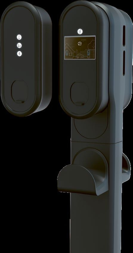
Product overview
The ePoleDuo serves as mounting
column for two eBoxes with two
eClicks. The modular concept of the eBox
overall product also allows for a eClick
separate installation of the ePoleDuo
in advance.
eClick
eBox
ePoleDuo
Included in delivery The following products can be ordered
separately:
• Cable hanger
1 Aluminium head with 1 lock • Concrete foundation
1 Aluminium column • Residual-current device (RCD)
1 Base plate • Circuit breaker
2 Cover plates for aluminium head
Assembly material
4 Screws for base plate
4 Screws with 4 washers
for aluminium head
4 M16 nuts with 4 washers with 4 caps
Note: To mount the eBoxes on the
ePoleDuo, you will need two eClicks;
they are not part of the ePoleDuo.
Caution
The contents of the delivery must be checked
for completeness and intactness.Product overview 27
01
Aluminium head
02
1 Cover plates for aluminium head
2
03
Lock
3
5
2 04
Aluminium column
05
Cable hanger (optional, not included)
5
06
Base plate
4
07
Concrete foundation (optional, not
included)
6
7
Specifications
Measurements H x W x D 1,608 mm x 208 mm x 175 mm (without cable hangers)
1,608 mm x 208 mm x 427 mm (with two cable hangers)
Dimensions of short variant H x W x D 1,280 mm x208 mm x 175 mm (without cable hangers)
1,280 mm x 208 mm x 427 mm (with two cable hangers)
Installation type Free-standing on concrete foundation
Weight 19,3 kg (short version 17,0 kg), cable hanger 1,5 kg
IP IP55 (with eBox or protective cover)
Operating temperature -30 °C to +50 °C28 ePoleDuo installation instructions
Installation
This chapter is split into installation, supply lines, assembly and
next steps.
Danger Caution
Before installing, familiarise Each eClick must be protected in
yourself with the safety the distribution box with a residual
instructions. current device and a circuit
breaker. Coordinate with the
customer in advance regarding the
desired power output and use the
protective components matching
the current (Table Y).
Before installing
Check and ensure that the electrical installation intended for No additional electrical devices may be integrated in any
connection can supply the required electrical power. of these circuits.
Each eClick must be protected, in the pre-installation, Before installing, first consult the owner or operator of
corresponding to the respective supply line, with an FI/ the system for the required output power, and fit
RCD (residual current device) and an LS (circuit breaker). adequate guards.
Line selection
When selecting the cable, the valid, international, country- The cable cross-section must be selected so that the self-
specific nd regional regulations and standards must be heating is limited to 15K.
observed. When selecting the cable, the connection to a
three-phase or single-phase AC circuit must be made in
accordance with the regulations and standards.Installation 29
RCD Variant 1 Variant 2
Charging power 3.7 kW; 11 kW 7.4 kW; 22 kW
Charging current 16 A 32 A
Example F204A, 4-pole, 25/0,03 A ABB F204 A, 4-pole, 40/0,03 A ABB
Standards DIN EN 61008-1/DIN EN 61008-2-1 DIN EN 61008-1/DIN EN 61008-2-1
Type A A
Operating voltage 230/400 V AC 230/400 V AC
Poles 4-pole 4-pole
Rated residual current 30 mA 30 mA
Rated current 25 A 40 A
Tripping time 300 ms 300 ms
Operating characteristic short-time delayed (AP-R)
Overvoltage category III III
Fouling factor 2 2
Tmax +55 °C, Tmax +55 °C,
Ambient temperature
Tmin -25 °C Tmin -25 °C
Material number 10284822 10118695
Circuit breaker Variant 1 Variant 2
Charging power 3.7 kW; 11 kW 7.4 kW; 22 kW
Charging current 16 A 32 A
Example S203-NA K, 20A ABB S203-NA K, 40A ABB
Standards DIN EN 60947-1, -2/DIN EN 60898-1 DIN EN 60947-1, -2/DIN EN 60898-1
Tripping characteristics K K
Poles 4-pole 4-pole
Rated switching capacity 6,000 A 6,000 A
Rated current 20 A 40 A
Insulation voltage 4 kV 4 kV
Overvoltage category III III
Fouling factor 2 2
Tmax +55 °C, Tmax +55 °C,
Ambient temperature
Tmin -25 °C Tmin -25 °C
Material number 10133671 10118694
• Installation of overvoltage protection equipment,
if demanded under national standards
• Routing of the connecting line to the installation site
Caution
• Connection of the supply line between the eClick / eBox For space reasons, the supply
and the sub-distribution line chosen must have whenever
possible a conductor area no
greater than 6 mm².30 ePoleDuo installation instructions
Choosing the site
Typically, the location of the ePoleDuo has been agreed Danger
upon with the customer, in advance of the installation, Do not install in and around
upon the on-site inspection. ex-zones!
For a smooth flow of the installation, the following prep
work must be performed.
Concrete foundation
The ePoleDuo must be installed on a concrete foundation.
Setting the concrete foundation
The fitting concrete foundation can be ordered from
innogy (article number 10122614). This concrete
foundation is equipped with four threaded bolts. The
ePoleDuo is mounted on the concrete foundation by
means of the base plate included in the scope of delivery.
Setup of the
charging pointInstallation 31
Tools needed
The following tools are needed to
assemble the ePoleDuo:
• Allen key 5 mm
• Cable ties
Open-ended spanner
• Open-ended spanner 24 mm
• Spirit level
• (Battery-operated) drill
Allen key
5 mm
Supply lines
Since each eClick must be equipped with a separate
residual current device and a circuit breaker in the
sub-distribution, it is necessary to feed two electrical
supply lines through the ePoleDuo.
Danger
There is a danger of electric
shock!
2 Supply lines
Danger
Make sure that the fusing for the
circuits has been disconnected
and there is no voltage across
the fitted components.32 ePoleDuo installation instructions
Lead the two electrical supply lines to the installation site.
There, keep at least 2,000 mm cable length available at the
installation point in order to be able to later feed the feeds
through the ePoleDuo and be able to connect the eClicks.
If the two eBoxes are to be connected via LAN, two
Ethernet cables must be laid analogously.
Danger
Make sure that the electrical
supply lines are voltage-free
during the entire installation.
Cable length at least
2,000 mm
Mounting
Before assembling the ePoleDuo, obtain an overview of
the steps required.Installation 33
01
Feed the electrical supply lines and,
where applicable, the Ethernet cables
through the concrete foundation. At the
top, at least two metres of each supply
line should still be available to you.
02
Place the aluminium column on the base
plate and screw it on with the four
screws provided. This step must take
place before the base plate is bolted
onto the concrete foundation.
03
Place the base plate bolted together
with the aluminium column on the
Caution
concrete foundation and bolt the base Tighten the nuts with a torque of
plate onto the bolts of the concrete at least 35 Nm.
foundation with the help of the washers,
nuts and caps that are included in the
scope of delivery.
04
In the meantime, connect the electrical
supply lines and, where applicable, the
Ethernet cables with cable ties to the
top end of the aluminium column.34 ePoleDuo installation instructions
05
If you would like to install cable
hangers, mount these now to the
aluminium column in accordance with
steps 05.01 to 05.04. Otherwise,
skip to Point 6.
05.03
Tighten the screws with the help of
an Allen wrench while fixating the
mounts with an open-ended spanner.
05.01
Push out, from the inside, the two
inserts each at the upper end of the
aluminium column.
05.04
Place the cable hanger on the
mounts and fixate it to the aluminium
column with the included metal piece
and the screw.
06
Before placing the aluminium
head onto the column, pre-drill
four holes with the battery-operated
drill. Put on the aluminium head
and you lead one supply line
for each side (electrical and if
necessary Ethernet cable) through
the aluminum head.
07
Finally, firmly bolt the aluminium
head to the aluminium column
with the four included washers
and screws.Next steps 35
Next steps
Subsequent to the assembly of the ePoleDuo:
• eClicks and eBoxes can be installed immediately or
• eClicks immediately and eBoxes later or
• eClicks and eBoxes later.
A) Installing eClicks and eBoxes immediately
If the eClicks and eBoxes are available, install them Danger
There is a danger of electric shock!
immediately.
01
The eClicks can be
02
Click in the two eBoxes.
03
On both sides, place the
installed in accordance cover plates of the
with the included eClick ePoleDuo onto the
installation instructions. aluminium head below the
eBoxes.36 ePoleDuo installation instructions
04
Lock the lock so that the
05
Hand the key to the owner
06
Commission the eBoxes in
two cover plates are locked. or operator of the accordance with the
ePoleDuo. included installation
The lever of the eClicks to instructions.
release the eBoxes is now
no longer accessible.
B) Installing eClicks and eBoxes later
If no eClicks are available, make sure that the supply lines Danger
There is a danger of electric shock!
are permanently in a voltage-free state.
01
If no eClicks are available,
02
Hand the key to the owner or
03
Leave the electrical supply
yet, fixate the supply lines operator of the ePoleDuo. line voltage-free so that
such that they are easily the supply lines are not
accessible for a later provided with voltage!
installation of the eClicks.Next steps 37
Dismounting
The eClick must be dismounted by a qualified electrician. de-installed in accordance with the eClick installation
instructions, the aluminium head can be unbolted and
For de-installation of the ePoleDuo, set the two eBoxes subsequently the aluminium column can be removed.
and eClicks voltage-free first. Leave the supply lines Unbolt the steel mounting bracket from the concrete
voltage-free for the whole duration of the de-installation. foundation.
The deinstallation of the eClicks and of the eBoxes is Ensure that the electrical supply lines are also
described in the eClick installation instructions. voltage-free after de-installation of the ePoleDuo.
As soon as the eClicks and the eBoxes have been
Disposal
Please dispose of the aluminium and steel parts in a
professional manner.38 ePoleDuo installation instructions
Legal notice   39

Legal notice

Copyright 2020 innogy eMobility Solutions GmbH. All rights reserved.
This document is intellectual property right- and copyright-protected.
No part hereof may be edited, duplicated, or published in any manner
purposing other than the proper installation of the ePoleDuo.

© innogy eMobility Solutions GmbH
Flamingoweg 1
44139 Dortmund
Germany

Head office: Dortmund, Germany
Registered as a company at
the Amtsgericht Dortmund,
trade register no. HRB 30359
eMob-85/04.20

innogy eMobility Solutions GmbH
Flamingoweg 1
44139 Dortmund
Deutschland
emobility@innogy.com
innogy-emobility.com
Sie können auch lesen