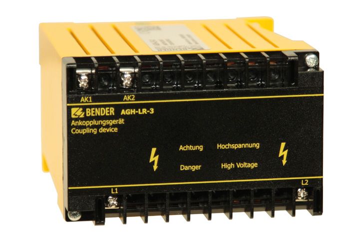
ISOMETER isoLR275 mit Ankoppelgerät AGH-LR with coupling device AGH-LR
←
→
Transkription von Seiteninhalten
Wenn Ihr Browser die Seite nicht korrekt rendert, bitte, lesen Sie den Inhalt der Seite unten
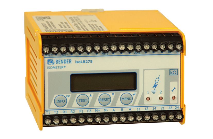
ISOMETER® isoLR275
mit Ankoppelgerät AGH-LR
with coupling device AGH-LR
Isolationsüberwachungsgerät für ungeerdete AC-, AC/DC- und DC-Stromversorgungen
(IT-Systeme) für Anlagen mit niederohmigem Isolationsniveau bis AC 793 V/DC 1100 V
Insulation monitoring device for unearthed AC, AC/DC and DC systems (IT systems)
for electrical installations with a low level of resistance up to AC 793 V/DC 1100 V

isoLR275_D00127_00_Q_DEEN / 03.2021                                    Quickstart DE/EN
ISOMETER® isoLR275

isoLR275 mit Ankoppelgerät AGH-LR                           isoLR275 with coupling device AGH-LR

    i      Bestandteil der Gerätedokumentation sind neben
           dieser Kurzanleitung die beiliegenden
                                                               i      Part of the device documentation in addition to
                                                                      this quickstart is the enclosed “Safety instructions
           „Sicherheitshinweise für Bender-Produkte“ und              for Bender products“ and the manual, which can
           das Handbuch, herunterladbar unter https://                be downloaded from https://www.bender.de/en/
           www.bender.de/service-support/downloadbe-                  service-support/downloads.The quickstart does
           reich. Die Kurzanleitung ersetzt nicht das                 not replace the manual.
           Handbuch.

Lieferumfang                                                Scope of delivery
    •   isoLR275                                               •   isoLR275
    •   Ankoppelgerät AGH-LR                                   •   Coupling device AGH-LR
    •   Sicherheitshinweise für Bender-Produkte                •   Safety instructions for Bender products
    •   Kurzanleitung DE/EN                                    •   Quickstart DE/EN
Bestellangaben                                              Ordering information
                           Nennspannung /          Versorgungsspannung /                           Handbuch Nr. /
        Typ/Type                                                             Art.-Nr. / Art. No.
                          Nominal voltage Un          Supply voltage Us                             Manual No.
isoLR275-327
                                                       AC 19,2…55 V
+ AGH-LR-3
                                                        42…460 Hz
bestehend aus:            3(N)AC 0…793 V
                                                       DC 19,2…72 V            B91065702W             D00127
consisting of:             DC 0…1100 V
                                                             ---
isoLR275-327
                                                             ---
AGH-LR
isoLR275-335
+ AGH-LR                  3(N) AC 0…793 V              AC 88…264 V
                                                                               B91065703W
bestehend aus:              DC 0…1100 V                DC 77…286 V
                                                                               B91065701W             D00127
consisting of:                   ---                        ---
                                                                               B98039022W
isoLR275-335                     ---                        ---
AGH-LR-3

Achtung: die Geräte isoLR275 mit AGH-LR werden im           Note: The two devices isoLR275 and AGH-LR are only
Set geliefert!                                              available as a set!
Zubehör für Schraubbefestigung Bestell-Nr.: B990056         Accessories for screw fixing - Order No.: B990056

Bestimmungsgemäße Verwendung                                Intended use
Das ISOMETER® ist bestimmt:                                 The ISOMETER® is intended for:
   • zur Überwachung des Isolationswiderstandes von           • Monitoring the insulation resistance of IT systems
      IT-Systemen                                           Any use other than that described in this quickstart is
Eine andere oder darüber hinausgehende Benutzung            regarded as improper.
gilt als nicht bestimmungsgemäß.                            Intended use also implies:
Zur bestimmungsgemäßen Verwendung gehört auch:
                                                               • Compliance with all information in this operating
    • das Beachten aller Hinweise aus der                        manual and
      Bedienungsanleitung und                                  • Compliance with any test intervals.
    • die Einhaltung eventueller Prüfintervalle.

2         isoLR275_D00127_00_Q_DEEN / 03.2021
ISOMETER® isoLR275
Montage Mounting
i Montieren Sie das isoLR275 und das AGH-LR mit
mindestens 30 mm Abstand zu allen benachbar-
i Install the isoLR275 and the AGH-LR with a
distance of at least 30 mm to all adjacent devices
ten Geräten! Der Abstand ist in allen Richtungen to ensure compliance with prescribed
zur Einhaltung der Temperaturgrenzen erforder- temperature limits. The cable lengths between
lich. Die Verbindungsleitungen zwischen AGH-LR AGH-LR and isoLR275 must not exceed 0.5 m.
und isoLR275 dürfen maximal 0,5 m lang sein.
i For UL applications:
i Für UL-Anwendungen:
Hochspannungsankoppelgeräte AGH-PV müssen
High voltage coupling devices AGH-PV should be
mounted min. 30.8 mm away from the walls of a
mit einem Mindestabstand von 30,8 mm zu allen metal enclosure and uninsulated grounded parts
benachbarten nicht isolierten geerdeten und and uninsulated live parts.
spannungsführen-den Komponenten sowie den
Metallwänden des Schaltschranks montiert wer-
den.
112,5 110
74
105
Klemmenabdeckung Ø 5,5 für Schraubbefestigung
Terminal cover Ø 5,5 for screw mounting
Maßangabe in mm Dimensions in mm
Anschluss Connection
i Für UL-Anwendungen:
Nur 60 °C/75 °C-Kupferleitungen verwenden! i For UL applications:
Use 60 °C/75 °C copper conductors only!
Für UL- und CSA-Applikationen sind For UL and CSA applications, the use of 5 A fuses
5-A-Vorsicherungen zwingend zu verwenden. is mandatory.
Anzugsmoment isoPV: 0,6…0,8 Nm/ Tightening torque: isoPV: 0.6 Nm…0.8 Nm,
AGH-PV: 0,5 Nm AGH-PV: 0.5 Nm
Mit einer externen „TEST“-Taste oder einer externen An external test button or an external reset button may
„RESET“-Taste darf nur ein ISOMETER® angesteuert wer- only be connected to one ISOMETER®. A parallel con-
den. Eine galvanische Parallelschaltung mehrerer nection of several test and reset inputs for collective
„TEST“- oder „RESET“-Eingänge für Sammelprüfungen ISOMETER® testing is not allowed.
von ISOMETER®n ist nicht erlaubt.
isoLR275_D00127_00_Q_DEEN / 03.2021 3ISOMETER® isoLR275
Anschlussbild Wiring diagram
3/N AC - system Un L1 L2
2 L1
L2
L3
+/~
Us
-/~ AGH-LR
6
N 1 AK1 AK2 PE
L1 L2
3 AC - system Un
L1 A1/+ A2/- AK1 AK2 KE
3 L2
L3
L1 L2 isoLR275 K1 K2
AC - system
4 Un
L1
L2 T1 T2 R1 R2 F1 F2 M+ M- A B 11 12 14 21 22 24
L1 L2
120
DC - system
5 Un
L+
mA
L-
L1 L2 7 8 9 10 11 12 13
Versorgungsspannung US (siehe Typenschild) über 1 Supply voltage US (see nameplate) via 6 A fuse
1
Schmelzsicherung 6 A
Connection to the 3 AC system to be monitored:
Anschluss an das zu überwachende 3 AC-System: 2, 3 Connect the terminals L1, L2 to neutral conductor N
2, 3 Klemmen L1, L2 mit Neutralleiter N oder or terminals L1, L2 to conductor L1, L2.
Klemmen L1, L2 mit Leiter L1, L2 verbinden
Connection to the AC system to be monitored:
4
Anschluss an das zu überwachende AC-System: connect terminals L1, L2 to conductor L1, L2.
4
Klemmen L1, L2 mit Leiter L1, L2 verbinden
Connection to the DC system to be monitored:
Anschluss an das zu überwachende DC-System: 5 Connect terminal L1 to conductor L+ and terminal L2 to
5
Klemme L1 mit Leiter L+, Klemme L2 mit Leiter L- verbinden conductor L-
6 Getrennter Anschluss von und KE an PE 6 Separate connection of and KE to PE
7* Externe „TEST“-Taste (Schließer) 7* External „TEST“ button (N/O contact)
Externe „RESET“-Taste (Öffner oder Drahtbrücke), External „RESET“ button (N/C contact or wire jumper),
8* bei offenen Klemmen wird keine Fehlermeldung 8* when the terminals are open, the fault message
gespeichert will not be stored.
STANDBY mit Hilfe des Funktionseingangs F1, F2: STANDBY by means of the function input F1, F2:
9* keine Isolationsfehlermessung bei geschlossenem 9* when the contact is closed, the insulation resistance
Kontakt; Trennung vom IT-System is not measured. Disconnection from the IT system
Stromausgang, galvanisch getrennt: Current output, electrically isolated:
10 10
0…20 mA oder 4…20 mA 0…20 mA or 4…20 mA
Serielle Schnittstelle RS-485 (Terminierung mittels Serial interface RS-485
11 11
120 Ω-Widerstand) (termination with a 120 Ω resistor)
12 Alarm-Relais 1; verfügbare Wechslerkontakte 12 Alarm relay 1; available changeover contacts
Alarm-Relais 2 (Gerätefehler-Relais); verfügbare Alarm relay 2 (device error relay);
13 13
Wechslerkontakte available changeover contacts
* Die Klemmenpaare 7, 8 und 9 müssen galvanisch ge- * The wiring of the terminal pairs 7, 8 and 9 must be
trennt verdrahtet werden und dürfen keine carried out galvanically isolated from each other and
Verbindung zu PE haben! must not have a connection to PE!
4 isoLR275_D00127_00_Q_DEEN / 03.2021ISOMETER® isoLR275
Inbetriebnahme-Schema Commissioning flow chart
Eingekreiste Ziffern im Schema korrespondieren mit The encircled figures in the flow chart correspond to
den Legenden-Ziffern im Anschlussbild. the figures in the legend to the wiring diagram.
Inbetriebnahme des ISOMETER®s (1) Commissioning of the ISOMETER® (1)
Is the system to be monitored an no isoLR is not suitable for this
nein isoLR275 ist für diese Anwendung
Ist die zu überwachende Stromversor- unearthed system (IT system)? application( contact Bender)
gung ein ungeerdetes IT-System ? nicht geeignet
(Fa. Bender kontaktieren)
Is the maximum nominal voltage
isoLR275 ist für diese Anwendung Un ≤ AC 793 V no isoLR is not suitable for this
Ist die Spannung Un ≤ AC 793 V ? nein
und ist nicht geeignet and is Un ≤ DC 1100 V application( contact Bender)
Un ≤ DC 1100 V ? (Fa. Bender kontaktieren)
Vor dem Anschließen des Gerätes die Deenergize the installation
Anlage spannungsfrei schalten ! before connecting the device!
yes yes
ja ja Recommended wire cross
Empfohlener section of connecting cable
Anschlussquerschnitt single wire 0.2...4 mm2
eindrähtig 0,2 ... 4 mm2 Geräteanschluss Device connection flexible 0.2... 2.5 mm2 Optional device
Geräteanschluss feindrähtig 0,2 ... 2,5 mm2 connection
optional
The two PE connections and KE An external kΩ measuring instrument
Die beiden Schutzleiterverbindungen must be connected separately to the 6 at M+/M-
und KE müssen einzeln an den 6 Ein externes k -Messinstrument
an M+/M- equipotential bonding. Scale centre point: 28 kΩ or 120 kΩ 10
Potentialausgleich angeschlossen werden Output current: 0/4...20 mA
Skalenmittelpunkt: 28 k oder 120 k 10
Ausg.-Strom: 0/4...20 mA 2
2 The terminals AK1 and AK2 must be
Die Klemmen AK1 und AK2 müssen über 3
ein AGH-LR an Un des zu überwachenden
3 connected by means of an AGH-LR
to Un of the system to be monitored 4 External TEST button (NO contact)
IT-Systems angekoppelt werden 4 Externe TEST-Taste (Schließerkontakt)
5 to the terminals T1 and T2 7
5 an die Klemmen T1 und T2 7
Connect the supply voltage Us
Schließen Sie die Versorgungsspg. Us to the terminals A1/+ and A2/-. Consider 1
an die Klemmen A1/+ und A2/- an. External RESET button (NC contact) 8
1 Externe RESET-Taste (Öffnerkontakt) 8 the details indicated on the nameplate. to the terminals R1 and R2
Angaben auf dem Typenschild beachten an die Klemmen R1 und R2
When using the RS485 interface, take The output contacts of the alarm relays 12
Bei Benutzung der RS-485-Schnittstelle Wechsler-Kontakte der Alarm-Relais 12 care that a 120 Ω resistor is connected System fault (21-22-24)
Systemfehler: 21-22-24 at the beginning and the end of the
11 Alarm 1 (11-12-14) 13
muss an den Enden des Netzwerks je 11 Alarm1 (11-12-14) 13
ein 120 -Widerstand angeschlossen sein network. Alarm 2 (21-22-24)
Alarm2 (21-22-24)
Inbetriebnahme des ISOMETER®s (2) Commissioning of the ISOMETER® (2)
Connect the supply
voltage US
The ISOMETER carries out a
Das ISOMETER® führt einen self test. The display indicates
Connect the voltage Un of the the insulation value after finishing
IT system to be monitored the measurement
Set the clock
Shall the basic setting
be changed? Select ISO SETUP
Alarm1 = 4 kΩ yes (see chapter operation and setting)
Alarm2 = 1 kΩ
K1/K2 = N/O operation
Memory = off
no
The insulation value of the system
Does one of the alarm LEDs being monitored is below the preset
light up? yes
response value. Change the response
value or improve the insulation
condition of the system
no
isoLR275_D00127_00_Q_DEEN / 03.2021 5ISOMETER® isoLR275
Inbetriebnahme des ISOMETER®s (3) Commissioning of the ISOMETER® (3)
Zur Kontrolle des ordnungs-
gemäßen Anschlusses ist eine
Funktionsprüfung mittels
eines geeigneten Widerstandes In order to check the proper
durchzuführen. connection, a functional test
Größe des Widerstandes: using a suitable resistance is
50% des eingestellten to be carried out.
Ansprechwertes Alarm2. Size of the resistance:
50% of the preset response
value Alarm 2.
Leuchten beide Alarm-LEDs? Anschlüsse kontrollieren !
Haben die Ausgangsrelais nein
Liegt die Nennspannung Un an den
geschaltet? Klemmen L1/L2 Check the connecting leads !
Do both alarm LEDs light up? no
des Ankoppelgeräts AGH-LR ? Did the alarm relays switch ? Is voltage Un applied to the
Spannungen mit einem terminals L1/L2 ?
ja geeigneten Voltmeter kontrollieren ! of the coupling device AGH-LR?
Check the voltages with a suitable
yes voltmeter !
Leuchten beide Alarm-LEDs?
Haben die Alarmrelais
geschaltet? Do both alarm LEDs light ?
Did the alarm relays switch?
ja
Widerstand entfernen ! yes
Remove the resistor !
nein
no
Sind die Alarm-LEDs erloschen ?
Haben die Alarmrelais Alarm LEDs extinguished ?
ihre Schaltstellung gewechselt ? Did the output relays change
their position ?
ja
yes
isoLR275 ist
funktionstüchtig isoLR is correctly
und richtig angeschlossen ! connected and functions reliably !
Menüstruktur Menu structure
*** IT-SYSTEM ***
R >1.0 MΩ H
MENU
1. EXIT
2. HISTORY INFO
3. ISO SETUP
4. ISO ADVANCED
ESC 5. COM SETUP
6. PASSWORD
7. LANGUAGE
8. SERVICE
ESC
HISTORY INFO ISO SETUP ISO ADVANCED COM SETUP PASSWORD LANGUAGE SERVICE
1. Exit
Nr.: 01 #Nr.: 02 2. AGH : LR 1. Exit Insert Service
Power on 3. Ce max: 150µF 2. Password: XXX Password: XXX
4. Measure: AMP 3. Status: off
5. Autotest: 24h
6. Clock: 19:08
7. Date: 01.01.01
8. Test: 00:00
1. Exit 1. Exit 1. Exit
2. Alarm1: 4.0 kΩ 2. Addr: 003 2. Text: Deutsch
3. Alarm2: 1.0 kΩ 3. ISONet: off
4. K1 : N.O 4. ISO Monitor
5. K2 : N.O
6. Memory: on
7. M+/M-: 0-20 mA
8. M+/M-: Ri: 28kΩ
6 isoLR275_D00127_00_Q_DEEN / 03.2021ISOMETER® isoLR275
Bedienelemente und Anzeigen Display and operating elements
LR275
4
„INFO“-Taste: Abfragen von Standardinformation/ „INFO“ button: to query standard information/
1 „ESC“-Taste: Zurück (Menü-Funktion), Bestätigung Para- 1 „ESC“ button: back (menu function), to confirm parameter
meteränderung change
„TEST“-Taste: Selbsttest aufrufen/ „TEST“ button: to call up the self test/
2 Aufwärts-Taste: Parameteränderung, im Menü aufwärts 2 Arrow up button: parameter change, to move up in the
bewegen menu
„RESET“-Taste: Löschen gespeicherter Isolationsfehler- „RESET“ button: to delete stored insulation fault alarms:
3
Alarme Down button: parameter change, to move down in the menu
3
Abwärts-Taste: Parameteränderung, im Menü abwärts „MENU“ button: to call up the menu system
bewegen 4
Enter button: Confirms parameter changes
„MENU“-Taste: Aufruf Menüsystem Alarm LED 1 lights: insulation fault, first warning level
4 5
Eingabe-Taste: Bestätigung Parameteränderung reached.
Alarm-LED 1 leuchtet: Isolationsfehler, erste Warnschwelle Alarm LED 2 lights: insulation fault, second warning level
5 6
erreicht reached.
Alarm-LED 2 leuchtet: Isolationsfehler, zweite Warnschwelle
6 7 Device error LED lights: isoLR275 faulty
erreicht
7 Gerätefehler-LED leuchtet: isoLR275 ist fehlerhaft 8 Two-line display for standard and menu mode
8 Zweizeiliges Display für Standard- und Menü-Betrieb
isoLR275_D00127_00_Q_DEEN / 03.2021 7ISOMETER® isoLR275 Technische Daten isoLR275 Technical data isoLR275 Die mit ** gekennzeichneten Angaben sind The values marked with** are absolute values. Absolutwerte. ()* = factory setting ()* = Werkseinstellung Isolationskoordination nach IEC 60664-1/ Insulation coordination acc. to IEC 60664-1/ IEC 60664-3 IEC 60664-3 Bemessungsspannung für isoLR275-3..................................AC 250 V Rated voltage for isoLR275-3................................................AC 250 V Bemessungs-Stoßspannung/Verschmutzungsgrad.................6 kV/III Rated impulse voltage/pollution degree.................................6 kV/III Bemessungsspannung..........................................................AC 250 V Rated insulation voltage.......................................................AC 250 V Bemessungs-Stoßspannung/Verschmutzungsgrad.................4 kV/III Rated impulse voltage/pollution degree.................................4 kV/III Spannungsbereiche Voltage ranges Netznennspannung Un....................................................über AGH-LR Nominal system voltage Un............................................... via AGH-LR isoLR275-335: isoLR275-335: Versorgungsspannung Us (siehe auch Gerätetypenschild).................. Supply voltage Us (also see nameplate).............................................. ................................................................................AC 88…264 V** ................................................................................AC 88…264 V** Frequenzbereich Us.........................................................42…460 Hz Frequency range Us.........................................................42…460 Hz Eigenverbrauch...................................................................≤ 21,5 VA Power consumption............................................................≤ 21.5 VA Versorgungsspannung Us (siehe auch Gerätetypenschild).................. Supply voltage Us (also see nameplate).............................................. ................................................................................DC 77…286 V** ................................................................................DC 77…286 V** Eigenverbrauch.....................................................................≤ 5,5 VA Power consumption..............................................................≤ 5.5 VA isoLR275-327: isoLR275-327: Versorgungsspannung Us (siehe auch Gerätetypenschild).................. Supply voltage Us (also see nameplate).............................................. ...............................................................................AC 19,2…55 V** ...............................................................................AC 19.2…55 V** Frequenzbereich Us.........................................................42…460 Hz Frequency range Us.........................................................42…460 Hz Versorgungsspannung Us (siehe auch Gerätetypenschild).................. Supply voltage Us (also see nameplate).............................................. ...............................................................................DC 19,2…72 V** ...............................................................................DC 19.2…72 V** Eigenverbrauch........................................................................≤ 6 VA Power consumption.................................................................≤ 6 VA Für UL-Anwendungen For UL applications Netznennspannung Un....................................................über AGH-LR Nominal system voltage Un............................................... via AGH-LR isoLR275-335: isoLR275-335: Versorgungsspannung Us (siehe auch Gerätetypenschild).................. Supply voltage Us (also see nameplate).............................................. ....................................................................................AC 88…250 V ....................................................................................AC 88…250 V Frequenzbereich Us.........................................................42…460 Hz Frequency range Us.........................................................42…460 Hz Eigenverbrauch AC..............................................................≤ 21,5 VA Power consumption AC.......................................................≤ 21.5 VA Versorgungsspannung Us (siehe auch Gerätetypenschild).................. Supply voltage Us (also see nameplate).............................................. ....................................................................................DC 80…250 V ....................................................................................DC 80…250 V Eigenverbrauch DC................................................................≤ 5,5 VA Power consumption DC.........................................................≤ 5.5 VA isoLR275-327: isoLR275-327: Versorgungsspannung Us (siehe auch Gerätetypenschild).................. Supply voltage Us (also see nameplate).............................................. ......................................................................................DC 24…65 V ......................................................................................DC 24…65 V Eigenverbrauch........................................................................≤ 6 VA Power consumption.................................................................≤ 6 VA 8 isoLR275_D00127_00_Q_DEEN / 03.2021
ISOMETER® isoLR275

Ansprechwerte                                                                                     Response values
Ansprechwert Ran1..........................................................0,2…100 kΩ             Response value Ran1........................................................0.2…100 kΩ
Werkseinstellung Ran1 (Alarm1)...................................................4 kΩ             Factory setting Ran1 (Alarm1).......................................................4 kΩ
Ansprechwert Ran2..........................................................0,2…100 kΩ             Response value Ran2........................................................0.2…100 kΩ
Werkseinstellung Ran2 (Alarm2)...................................................1 kΩ             Factory setting Ran2 (Alarm2).......................................................1 kΩ
Ansprechunsicherheit (7 kΩ…100 kΩ) (nach IEC 61557-8)....±15 %                                    Relative uncertainty (7 kΩ…100 kΩ) (acc. to IEC 61557-8)....±15 %
Ansprechunsicherheit (0,2 kΩ…7 kΩ).....................................±1 kΩ                      Relative uncertainty (0.2 kΩ…7 kΩ)........................................±1 kΩ
Hysterese........................................................................25 %, +1 kΩ      Hysteresis........................................................................25 %, +1 kΩ
Ausgänge/Eingänge                                                                                 Outputs/Inputs
„TEST“-/„RESET“-Taste...................................................intern/extern             „TEST“-/„RESET“ button...........................................internal/external
Leitungslänge „TEST“-/“RESET“-Taste extern.........................≤ 10 m                         Cable length „TEST“-/“RESET“ button, external......................≤ 10 m
Stromausgang (Bürde)................................. 0/4…20 mA (≤ 500 Ω)                         Current output (load).................................... 0/4…20 mA (≤ 500 Ω)
Genauigkeit Stromausgang,                                                                         Accuracy current output,
bezogen auf den angezeigten Wert (1 kΩ…100 kΩ).........................                           related to the value indicated (1 kΩ…100 kΩ)..................................
...................................................................................±15 %, ±1 kΩ   ...................................................................................±15 %, ±1 kΩ
Serielle Schnittstelle                                                                            Serial interface
Schnittstelle/Protokoll....................................................RS-485/BMS             Interface/protocol...........................................................RS-485/BMS
Anschluss......................................................................Klemmen A/B        Connection.................................................................... terminals A/B
Leitungslänge.....................................................................≤ 1200 m        Cable length......................................................................≤ 1,200 m
Geschirmte Leitung (Schirm einseitig an PE)......................................                 Shielded cable (shield to PE on one end)............................................
...........................................2-adrig, ≥ 0,6 mm2, z. B. J-Y(St)Y 2 x 0,6             .............................................2-core, ≥ 0.6 mm2, e.g. J-Y(St)Y 2 x 0.6
Abschlusswiderstand....................................................120 Ω (0,5 W)              Terminating resistor.....................................................120 Ω (0.5 W)
Geräteadresse, BMS-Bus.................................................. 1…30 (3)*                Device address, BMS bus.................................................. 1…30 (3)*
Umwelt/EMV                                                                                        Environment/EMC
EMV                                                                                               EMC
nicht für Haushalt und Kleingewerbe geeignet..................................                    not suitable for household and small companies................................
.........................................................................IEC 61326-2-4 Ed. 1.0    .........................................................................IEC 61326-2-4 Ed. 1.0
Arbeitstemperatur....................................................-25 ºC…+65 ºC                Operating temperature.............................................-25 ºC…+65 ºC
Klimaklassen nach IEC 60721:                                                                      Classification of climatic conditions acc. to IEC 60721:
Ortsfester Einsatz (IEC 60721-3-3)......................................................          Stationary use (IEC 60721-3-3)...........................................................
................................................. 3K23 (mit Betauung und Eisbildung)              .................................3K23 (with condensation and formation of ice)
Transport (IEC 60721-3-2)........ 2K11 (mit Betauung und Eisbildung)                              Transport (IEC 60721-3-2)..................................................................
Langzeitlagerung (IEC 60721-3-1)......................................................            .................................2K11 (with condensation and formation of ice)
................................................. 1K22 (mit Betauung und Eisbildung)              Long-term storage (IEC 60721-3-1)....................................................
Mechanische Beanspruchung nach IEC 60721:                                                         .................................1K22 (with condensation and formation of ice)
Ortsfester Einsatz (IEC 60721-3-3)......................................................          Classification of mechanical conditions acc. to IEC 60721:
bei Schraubmontage mit Zubehör B990056..............................3M12                          Stationary use (IEC 60721-3-3)...........................................................
bei Montage auf Hutschiene......................................................3M11              for screw fixing with accessories B990056.................................3M12
Transport (IEC 60721-3-2)...........................................................2M4           for DIN rail mounting.................................................................3M11
Langzeitlagerung (IEC 60721-3-1).............................................1M12                 Transport (IEC 60721-3-2)...........................................................2M4
                                                                                                  Long-term storage (IEC 60721-3-1)...........................................1M12

                                                                                                     isoLR275_D00127_00_Q_DEEN / 03.2021                                                            9
ISOMETER® isoLR275
Anschluss Connection
Anschlussart............................................................ Schraubklemmen Connection type................................................ screw-type terminals
Anschluss, starr/flexibel........................ 0,2…4 mm2/0,2…2,5 mm2 Connection, rigid/flexible..................... 0.2…4 mm2/0.2…2.5 mm2
Anschluss, flexibel mit Aderendhülse, ohne/mit Kunststoffhülse....... Connection flexible with ferrule, without/with plastic sleeve............
................................................................................. 0,25…2,5 mm2 ................................................................................. 0.25…2.5 mm2
Anzugsmoment...................................................................... 0,5 Nm Tightening torque................................................................... 0.5 Nm
Leitergrößen (AWG)...............................................................24…12 Conductor sizes (AWG)...........................................................24…12
Länge der Verbindungsleitung zwischen isoLR275 und AGH-LR......... Cable length between isoLR275 and AGH-LR.....................................
..............................................................................................≤ 0,5 m ..............................................................................................≤ 0.5 m
Sonstiges Other
Betriebsart..................................................................... Dauerbetrieb Operating mode................................................ continuous operation
Einbaulage..........................................................orientiert an Display Mounting..................................................................display-oriented
Abstand zu benachbarten Geräten......................................≥ 30 mm Distance to adjacent devices................................................≥ 30 mm
Schutzart, Einbauten (DIN EN 60529)..........................................IP30 Degree of protection, internal components (DIN EN 60529)........IP30
Schutzart, Klemmen (DIN EN 60529)...........................................IP20 Degree of protection, terminals (DIN EN 60529)..........................IP20
Schnellbefestigung auf Hutprofilschiene..... DIN EN 60715/IEC 60715 DIN rail mounting........................................ DIN EN 60715/IEC 60715
Schraubbefestigung mittels Halterung.................................... 2 x M4 Screw mounting by means of support..................................... 2 x M4
Entflammbarkeitsklasse....................................................... UL94 V-0 Flammability class............................................................... UL94 V-0
Gewicht..................................................................................< 510 g Weight...................................................................................< 510 g
Technische Daten AGH-LR Technical data AGH-LR
Isolationskoordination nach IEC 60664-1 Insulation coordination acc. to IEC 60664-1
Bemessungsspannung..........................................................AC 800 V Rated insulation voltage.......................................................AC 800 V
Bemessungsstoßspannung/Verschmutzungsgrad....................8 kV/3 Rated impulse voltage/pollution degree..................................8 kV/3
Spannungsbereiche Voltage ranges
Netznennspannung Un.............AC, 3(N)AC 0…793 V, DC 0…1100 V Nominal system voltage Un.....AC, 3(N)AC 0…793 V, DC 0…1,100 V
Nennfrequenz fn........................................................DC, 10…460 Hz Nominal frequency fn................................................DC, 10…460 Hz
Max. Wechselspannung U~ im Frequenzbereich fn = 0,1…10 Hz:... Max. AC voltage U~ in the frequency range fn = 0.1…10 Hz:...........
.........................................................................U~ max = 110 V/Hz * fn .........................................................................U~ max = 110 V/Hz * fn
Umwelt/EMV Environment/EMC
EMV..................................................................IEC 61326-2-4 Ed. 1.0 EMC...................................................................IEC 61326-2-4 Ed. 1.0
Arbeitstemperatur....................................................-25 ºC…+65 ºC Operating temperature.............................................-25 ºC…+65 ºC
Klimaklassen nach IEC 60721: Classification of climatic conditions acc. to IEC 60721:
Ortsfester Einsatz (IEC 60721-3-3)...................................................... Stationary use (IEC 60721-3-3)...........................................................
................................................. 3K23 (mit Betauung und Eisbildung) .................................3K23 (with condensation and formation of ice)
Transport (IEC 60721-3-2)........ 2K11 (mit Betauung und Eisbildung) Transport (IEC 60721-3-2)..................................................................
Langzeitlagerung (IEC 60721-3-1)...................................................... .................................2K11 (with condensation and formation of ice)
................................................. 1K22 (mit Betauung und Eisbildung) Long-term storage (IEC 60721-3-1)....................................................
Mechanische Beanspruchung nach IEC 60721: .................................1K22 (with condensation and formation of ice)
Ortsfester Einsatz (IEC 60721-3-3).............................................3M12 Classification of mechanical conditions acc. to IEC 60721:
Transport (IEC 60721-3-2)...........................................................2M4 Stationary use (IEC 60721-3-3)..................................................3M12
Langzeitlagerung (IEC 60721-3-1).............................................1M12 Transport (IEC 60721-3-2)...........................................................2M4
Long-term storage (IEC 60721-3-1)...........................................1M12
10 isoLR275_D00127_00_Q_DEEN / 03.2021ISOMETER® isoLR275
Anschluss Connection
Anschlussart............................................................ Schraubklemmen Connection type................................................ screw-type terminals
Anschluss, starr/flexibel........................ 0,2…4 mm2/0,2…2,5 mm2 Connection, rigid/flexible..................... 0.2…4 mm2/0.2…2.5 mm2
Anschluss, flexibel mit Aderendhülse, ohne/mit Kunststoffhülse....... Connection flexible with ferrules, without/with plastic sleeve...........
................................................................................. 0,25…2,5 mm2 ................................................................................. 0.25…2.5 mm2
Anzugsmoment...................................................................... 0,5 Nm Tightening torque................................................................... 0.5 Nm
Leitergrößen (AWG)...............................................................24…12 Conductor sizes (AWG)...........................................................24…12
Länge der Verbindungsleitung zwischen isoLR275 und AGH-LR......... Cable length between isoLR275 and AGH-LR.....................................
..............................................................................................≤ 0,5 m ..............................................................................................≤ 0.5 m
Sonstiges Other
Betriebsart..................................................................... Dauerbetrieb Operating mode................................................ continuous operation
Einbaulage.........Kühlschlitze müssen senkrecht durchlüftet werden! Mounting......................... cooling slots must be ventilated vertically!
Abstand zu benachbarten Geräten......................................≥ 30 mm Distance to adjacent devices................................................≥ 30 mm
Schutzart, Einbauten (DIN EN 60529)..........................................IP30 Degree of protection, internal components (DIN EN 60529)........IP30
Schutzart, Klemmen (DIN EN 60529)...........................................IP20 Degree of protection, terminals (DIN EN 60529)..........................IP20
Schnellbefestigung auf Hutprofilschiene..... DIN EN 60715/IEC 60715 DIN rail mounting........................................ DIN EN 60715/IEC 60715
Schraubbefestigung................................................................. 2 x M4 Screw mounting...................................................................... 2 x M4
Entflammbarkeitsklasse....................................................... UL94 V-0 Flammability class............................................................... UL94 V-0
Gewicht..................................................................................< 230 g Weight...................................................................................< 230 g
Normen, Zulassungen und Zertifizierungen Standards, approvals and certifications
Das ISOMETER® wurde unter Beachtung folgender The ISOMETER® was designed in compliance with the
Normen entwickelt: following standards:
• DIN EN 61557-8 (VDE 0413-8) • DIN EN 61557-8 (VDE 0413-8)
• IEC 61557-8 + Corrigendum • IEC 61557-8 + Corrigendum
• IEC 61326-2-4 • IEC 61326-2-4
• DIN EN 60664-1 (VDE 0110-1) • DIN EN 60664-1 (VDE 0110-1)
• DIN EN 60664-3 (VDE 0110-3) • DIN EN 60664-3 (VDE 0110-3)
isoLR275_D00127_00_Q_DEEN / 03.2021 11isoLR275_D00127_00_Q_DEEN / 03.2021/ pdf / © Bender GmbH & Co. KG, Germany – Subject to change! The specified standards take into account the edition valid until 03/2021 unless otherwise indicated. Alle Rechte vorbehalten. All rights reserved. Nachdruck und Vervielfältigung Reprinting and duplicating nur mit Genehmigung des Herausgebers. only with permission of the publisher. Bender GmbH & Co. KG Bender GmbH & Co. KG Postfach 1161 • 35301 Grünberg • Deutschland PO Box 1161 • 35301 Grünberg • Germany Londorfer Str. 65 • 35305 Grünberg • Deutschland Londorfer Str. 65 • 35305 Grünberg • Germany Tel.: +49 6401 807-0 • Fax: +49 6401 807-259 Tel.: +49 6401 807-0 • Fax: +49 6401 807-259 E-Mail: info@bender.de • www.bender.de E-Mail: info@bender.de • www.bender.de
Sie können auch lesen


