MP Rekonstruktionsprothese - zementfrei MPTM Reconstruction Prosthesis
←
→
Transkription von Seiteninhalten
Wenn Ihr Browser die Seite nicht korrekt rendert, bitte, lesen Sie den Inhalt der Seite unten
081043 Link Umschlag.qxd                             25.06.2008   11:25 Uhr   Seite 1

          © W. LINK 2004 • 664dt-en SurgTech/06.08

                                                                                                                            MP® Rekonstruktionsprothese
                                                                                                                            zementfrei

                                                                                                                            MPTM Reconstruction Prosthesis
                                                                                                                            cementless

                                                                       WALDEMAR LINK GmbH & Co. KG
                                                                       Barkhausenweg 10 . D-22339 Hamburg
                                                                       Postfach 63 05 52 . D-22315 Hamburg
                                                                       Tel +49 (0)40 5 39 95-0 . Fax +49 (0)40 5 38 69 29
                                                                                                                            OP-Technik
                                                                       e-mail info@linkhh.de . Internet www.linkhh.de       Surgical Technique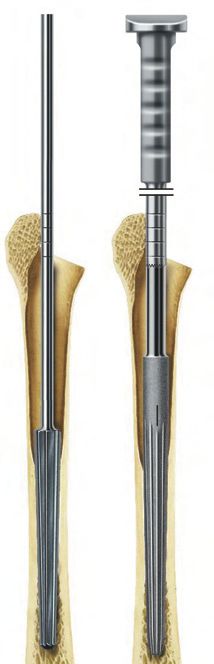
081043 Link Umschlag.qxd 25.06.2008 11:25 Uhr Seite 2
Ausführliche Informationen zu unseren Implantaten sind auf Wunsch erhältlich. More detailed information about our implants can be supplied upon request.
Folgende Materialien werden für unsere Implantate verwendet: Materials used for our orthopaedic implants:
• CoCrMo-Legierung gem. ISO 5832-4/ASTM F75 oder ISO 5832-12 • CoCrMo alloy, ISO 5832-4/ASTM F75 or ISO 5832-12
• TiAl6V4-Legierung gem. ISO 5832-3/ASTM F136 oder ASTM F1108 • TiAI6V4 alloy, ISO 5832-3/ASTM F136 or ASTM F1108
• Unlegiertes Titan gem. ISO 5832-2/ASTM F67 • Unalloyed titanium, ISO 5832-2/ASTM F67
• Rostfreier Stahl gem. ISO 5832-1/ASTM F138/ASTM F139 • Stainless steel, ISO 5832-1/ASTM F138 / ASTM F139
• CoCrNiMoFe gem. ISO 5832-7/ASTM F1058 • CoCrNiMoFe, ISO 5832-7/ASTM F1058
• UHMWPE gem. ISO 5834-2/ASTM F648 • UHMWPE, ISO 5834-2/ASTM F648
• Calcium-Phosphat-Beschichtung gem. ASTM F1609 • Calcium phosphate coating, ASTM F1609
• Hydroxylapatit-Beschichtung gem. ASTM F1185 • Hydroxyapatite coating, ASTM F1185
• Al2O3 (Aluminiumoxidkeramik) BIOLOX®forte* gem. ISO 6474 / ASTM F603 • AI2O3 (aluminium oxide ceramic) BIOLOX®forte*, ISO 6474 / ASTM F603
• Keramik BIOLOX®delta* gem. DC 25 • Ceramic BIOLOX®delta*, DC 25
* BIOLOX®forte und BIOLOX®delta sind Produkte der CeramTec AG, Plochingen, Germany * BIOLOX®forte and BIOLOX®delta are products of CeramTec AG, Plochingen, Germany
Bei der Verwendung unserer Implantate ist Folgendes zu beachten: Please note the following regarding the use of our implants:
1. Die korrekte Auswahl des Implantates ist extrem wichtig. 1. Choosing the correct implant is extremely important.
Größe und Form des menschlichen Knochens setzen der Größe und The size and shape of human bones restrict the size and shape of the
Form des Implantates Grenzen. Damit wird aber auch die Belastbarkeit implant. This also restricts the implant’s ability to withstand stress.
begrenzt. Implantate sind nicht dafür geeignet, die uneingeschränkte Implants are not designed to withstand unlimited body loads.
Körperbelastung zu tragen. Die Beanspruchung sollte mit der normalen The physical demand on implants should not surpass normal functional
funktionellen Belastung limitiert werden. stresses.
2. Die korrekte Handhabung des Implantates ist äußerst wichtig. 2. It is also very important to treat implants correctly.
Eine nachträgliche Verformung beeinträchtigt die Haltbarkeit des Altering the shape of a finished implant reduces its lifespan. The
Implantates. Folgende Manipulationen dürfen unter keinen Umständen following must be actively avoided: bending the implant sharply, bending
vorgenommen werden: Scharfes Biegen oder Abknicken, Zurückbiegen, it back, or making grooves or scratches in it. Our implants may not be
Riefen oder Kratzen. Die Kombination unserer Implantate mit combined with implants from other manufacturers.
Implantaten anderer Hersteller ist nicht gestattet.
3. Implants must not be re-used.
3. Kein Implantat darf wieder verwendet werden. Even if a used implant looks undamaged externally, it must be
Auch wenn das Implantat unbeschädigt aussieht, muss mit internen assumed that the material has become fatigued internally.
Materialermüdungen gerechnet werden.
Überreicht durch:
4. Patient rehabilitation is also very important.
Presented by: 4. Die Nachbehandlung ist ebenfalls sehr wichtig.
The patient must learn about the limitations of the implant. An implant
Der Patient muss auf die Grenzen der Belastbarkeit des Implantates
cannot compare with healthy bone in the ability to withstand stress!
hingewiesen werden. Die Belastbarkeit eines Implantates ist nicht mit der
eines gesunden Knochens vergleichbar !
5. Unless otherwise stated, implants are shipped in sterile packaging.
5. Die Implantate sind, sofern nicht anders angegeben, steril verpackt. The following are important for storage of packaged implants:
Bei der Lagerung der verpackten Implantate ist Folgendes zu beachten: • Avoid extreme or sudden changes in temperature.
• Keine starken oder schnellen Temperaturschwankungen. • We recommend a storage temperature of 18 – 22 °C with
• Empfohlen wird eine Lagertemperatur von 18 °C bis 22 °C mit einer 50 – 65 % humidity.
Luftfeuchtigkeit von 50 % bis 65 %. • Avoid direct sunlight.
• Kein direktes Sonnenlicht. • Protect implants from damp and from mechanical damage.
• Vor Nässe und mechanischen Beschädigungen schützen. • Implants may be stored for up to 5 years in their original packaging.
• Die Lagerzeit originalverpackter Implantate ist auf maximal 5 Jahre The ‘Use by’ date is on the product label.
begrenzt. Die Angabe des Verfallsdatums erfolgt auf dem Produktetikett. • Do not use an implant if its packaging has been damaged.
• Keine Implantate mit beschädigter Verpackung verwenden.
6. The documentation trail is important.
6. Die Rückverfolgbarkeit ist wichtig, Please use the documentation sticker included in the packaging for
bitte verwenden Sie hierzu die der Verpackung beigefügten this purpose.
Dokumentationsaufkleber.
WALDEMAR LINK GmbH & Co. KG, Hamburg WALDEMAR LINK GmbH & Co. KG, Hamburg
Alle in diesem Katalog veröffentlichten Beiträge, Abbildungen und Daten All materials in this catalogue, including text, pictures and data, are
sind urheberrechtlich geschützt. Jede vom Urheberrechtsgesetz nicht protected by the relevant copyright provisions. Every use of this material
zugelassene Verwertung bedarf unserer vorherigen Zustimmung. Dies gilt that is not allowed by the German Copyright Act is subject to our prior
insbesondere für Vervielfältigung, Bearbeitung, Übersetzung, Einspeicher- consent. This especially applies for reproduction, alteration, translation
ung, Verarbeitung bzw. Wiedergabe von Inhalten in Datenbanken oder and or publication of electronically or otherwise saved, modified and / or
WALDEMAR LINK GmbH & Co. KG anderen elektronischen Medien und Systemen. Die Angaben in diesem published contents. All information contained in this catalogue is solely
Barkhausenweg 10 . D-22339 Hamburg Katalog dienen lediglich der Produktbeschreibung und beinhalten keine intended for the description of products and shall under no means estab-
Garantie. lish any kind of warranty.
Postfach 63 05 52 . D-22315 Hamburg
Tel +49 (0)40 5 39 95-0 . Fax +49 (0)40 5 38 69 29 Alle Instrumente sind, sofern nicht anders gekennzeichnet, aus rostfreiem All instruments, unless otherwise noted, are made of Stainless Steel.
Stahl hergestellt.
e-mail info@linkhh.de . Internet www.linkhh.de
081043 Link Inhalt KORRI   27.06.2008   9:08 Uhr   Seite 1

                                                                                                          Systembeschreibung
                                                                                                           System Description
              Inhalt - Contents

                                                                                                          Indikationen/Kontraindikationen
                                                                                                            Indications/Contraindications
           MP® Rekonstruktionsprothese, zementfrei

           MPTM Reconstruction Prosthesis, cementless

                                                                                                          Operationstechnik
               Systembeschreibung                            System Description

                                                                                                           Surgical Technik
            2 Problemstellung                                The Problem
            2 Modulare Komponenten                           Modular Components
            4 Indikationen / Kontraindikationen              Indications / Contraindications
            4 Präoperative Planung                           Preoperative Planning

               Operationstechnik                             Surgical Technique

                                                                                                          Zusätzliche Instrumente
            5 Prothesenentfernung                            Removal of Prostheses

                                                                                                           Additional Instruments
            6 Auffräsen des Markkanals                       Reaming of Femoral Canal
            8 Einschlagen des Schaftes                       Impaction of Stem
           10 Vorbereitung des metaphysären Markraums Preparation of the Metaphyseal Cavity
           12 Probereposition                                Trial Reduction
           14 Beinlänge und Lateralisierung,                 Leg Length and Lateralization,
               Anteversion, Probe-Befestigungsschraube,      Anteversion, Trial Fixation Screw,
               Verwendung eines längeren Probehalsteiles Using a Longer Trial Neck Segment
           16 Endmontage:                                    Final Assembly:
               Montage Halsteil, Dehnschraube,               Seating of the Trial Neck Segment,
                                                                                                          Accessories
                                                                                                           Zubehör

               Montage Prothesenkopf                         Expansion Bolt, Placing of Prosthesis Head
           18 Schaftextraktion                               Stem Removal

               Zubehör                                       Accessories
           20 Instrumente                                    Instruments
           20 Röntgenschablonen                              X-ray templates
           21 Titan Cerclageband n. Thabe                    Thabe Titanium Cerclage Band
           22 Literatur                                      Literature
                                                                                                          Literature
                                                                                                          Literatur

           25 Wichtige Hinweise                              Important Information

                                                                                                    |1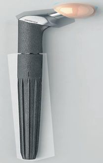
081043 Link Inhalt KORRI    27.06.2008     9:09 Uhr    Seite 2

                                                                                     Systembeschreibung

              Problemstellung                                             The Problem
           In den letzten Jahren wurde insbesondere bei jüngeren        In recent years there has been a sharp increase in the
           Patienten eine erhebliche Zunahme an Lockerungen von         number of hip stem prostheses that have become loose
           Hüftprothesenschäften mit ausgedehnten, meist                necessitating a procedure to revise the stem,
           proximal gelegenen Femurdefekten beobachtet, die             particularly among the more active patients. Often
           Maßnahmen zur Schaftrevision erforderlich machten.           times, extensive bone loss in the proximal femoral
                                                                        region is associated with these cases.
           Die Erfahrungen in der Revisionsendoprothetik mit
           zementierten langen Prothesenschäften zeigen, dass           Clinical experience has shown that the use of long
           man hiermit das Problem kurz- und mittelfristig recht gut    cemented stems in revision hip arthroplasty in patients
           lösen kann. Allerdings werden vorhandene Knochen-            with extensive proximal bone loss produces good short
           defekte mit Knochenzement eher „plombiert“, und zu           to medium term results. However, the use of cement
           einer Erholung des geschädigten proximalen Femurs            in cases of large proximal defects has not helped to
           kann es nicht kommen. Somit ist die Langzeithaltbarkeit      promote positive bone remodeling of the extensively
           des zementierten Gelenkersatzes nicht unproblematisch.       damaged proximal femur. Therefore, use of cemented
           Dagegen haben sich zementfrei eingesetzte Schäfte in         stems in revisions in femurs with large proximal
           diesen Fällen bewährt.                                       defects has proven to be problematic in the long-term.
                                                                        Cementless stems have been clinically proven to be
           Zementlose Prothesenschäfte mit einer „porous                successful in these cases.
           coated“ Oberfläche haben nachweislich zu einer stabilen
           distalen Verankerung geführt, wobei ein „remodeling“ die     Cementless femoral hip stems that are extensively
           Knochenneubildung im proximalen Femur offenbar nicht         porous coated have proven to promote distal fixation in
           behindert. Dennoch werden voll beschichtete, nicht           the femur for stability and do not seem to impede bone
           modulare Schäfte der stärkeren Schaftgrößen als zu steif     remodeling to repair proximal defects. However, fully
           angesehen, deren Entfernung nach erfolgtem Knochen-          coated one-piece stems are considered to be too stiff in
           einbau oft schwierig ist. Zudem bieten diese Schäfte nicht   the larger sizes and promote ingrowth that is often
           immer Lösungen für Probleme, die bei einer Revision          associated with difficult removal. In addition, these
           auftreten können, z.B. proximal / distale Schaftgrößen-      stems may not always adequately address some of the
           differenzen, Beinlängenunterschiede, Einstellung der         other issues faced when revising hip stems. Often times
           richtigen Anteversion und Entfernung des Prothesen-          the need to resolve issues such as proximal/distal
           schaftes. Diese Probleme können vorteilhafter mit            femoral size mismatch, leg length discrepancies, version
           modularen Hüftschäften bewältigt werden.                     adjustment and potential removal are better addressed
                                                                        by revision hip stems that provide modularity.
           Der MP ® Rekonstruktionsschaft ist ein modularer,
           zementloser Femurschaft, der für die Revision von            The MP TM Reconstruction Hip Stem is a modular
           Hüftprothesen bei massivem, proximalen Knochen-              cementless femoral hip stem that is designed for the
           verlust konzipiert wurde. Modulare proximale und distale     revision of failed hip stems, particularly when there is
           Schaftkomponenten erlauben eine Anpassung an die             extensive proximal bone loss. Modular proximal and
           Größenverhältnisse im Markraum. Geriefte konische            distal segments better address size mismatch. Tapered
           Schäfte reduzieren die Steifigkeit. Die mikroporöse          and fluted stems have reduced stiffness. The
           Oberfläche, auch mit einer HX® Beschichtung (Kalzium-        microporous surface, also available with HX® Coating
           phosphat) verfügbar, fördert den Knochenanwuchs. Das         (Calcium Phosphate), promotes bone ongrowth. The
           proximale Halsteil kann in die optimale Anteversions-        proximal Neck Segment can be positioned for optimal
           stellung gebracht werden. Mit Hilfe proximaler               version. Leg length can be adjusted with unique
           Zwischenringe kann die Beinlänge korrigiert werden.          proximal spacers.

              Modulare Komponenten                                         Modular Components
           Der MP® Rekonstruktionsschaft besteht aus folgenden          The MPTM Reconstruction Hip Stem modular
           Komponenten:                                                 components:
              Prothesenköpfe                                               Femoral Heads
              - CoCrMo Legierung oder Aluminiumoxidkeramik                 - CoCrMo Alloy or Aluminum Oxide Ceramic
              - 28, 32 und 36 mm Kopfdurchmesser mit bis zu                - 28, 32 and 36 mm head diameters with up to
                4 Kopfhalslängen                                             4 Neck Lengths
              Halsteile                                                    Neck Segments
              - Tilastan® Titanlegierung                                   - Tilastan® Titanium Alloy
              - 35 mm und 65 mm                                            - 35 mm and 65 mm
              - mit Kragen / ohne Kragen                                   - Collared and Collarless
              - CCD Winkel 126º und 135º                                   - 126° and 135° CCD Angle
              - Standard oder mit zusätzlicher Lateralisierung             - Standard or additional lateral Offset
              Proximale Zwischenringe (wahlweise)                          Spacers (optional)
              - CoCrMo Legierung                                           - CoCrMo Alloy
              - Mögliche Beinlängenkorrektur: 10, 20, 30 mm                - Ability to add 10, 20 or 30 mm of leg length
              Prothesenschäfte                                             Stems
              - Tilastan® Titanlegierung                                   - Tilastan® Titanium Alloy
              - 6 Schaftlängen: 160, 180, 210, 250, 290 und 330 mm         - 6 lengths: 160, 180, 210, 250, 290 and 330 mm
              - 7 Durchmesser: 12, 14, 16, 18, 20, 22,5 und 25 mm          - 7 diameters: 12, 14, 16, 18, 20, 22.5 and 25 mm
              Dehnschraube                                                 Expansion Bolts
              - CoCrMo Legierung                                           - CoCrMo Alloy
              - Zur Sicherung der Verbindung von Halsteil,                 - To secure assembly of Neck Segment Spacer
                Zwischenring(en) und Schaft.                                 and Stem

     2|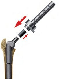
081043 Link Inhalt KORRI 27.06.2008 9:09 Uhr Seite 3
Systembeschreibung
System Description
System Description
Modulare Komponenten Modular Components
Prothesenköpfe A Prothesenköpfe A
Prosthesis Heads A Prosthesis Heads A
Indikationen/Kontraindikationen
Indications/Contraindications
BIOLOX® forte* BIOLOX® delta*
3 KH-Längen 3 KH-Längen
3 Neck Lengths 3 Neck Lengths
Dehnschrauben Ø 28, 32, 36 mm Ø 28, 32, 36 mm
Expansion Bolts
41 + 61 mm Prothesenköpfe B
Zusätzliche Halsteile: Prosthesis Heads B
Additional Neck Segments: CoCrMo Legierung
4 KH-Längen
4 Neck Lengths
Ø 28 + 32 mm
Halsteile
ohne Kragen
Operationstechnik
Surgical Technik
Neck Segments
XXL- mit und ohne Kragen without Collar
Mit Kragen / with Collar XXL- with and without Collar 65 + 35 mm
65 + 35 mm 65 + 35 mm
35 mm Halsteile nur ohne
Zwischenringe verwenden
Zwischenringe 35 mm Neck Segments use
Spacers only without Spacers
10 + 20 mm
Zusätzliche Instrumente
Additional Instruments
Schäfte
Stems
160 mm Schaft nur
Ø mm
mit 35 mm Halsteil
14
und ohne
16
Zwischenringe
18
verwenden
20
160 mm Stems use 22.5
only with 35 mm 25
Neck Segment and (160 - 330 mm)
without Spacer
Ø mm
Accessories
12
Zubehör
(160 - 250 mm)
180 mm
160 mm
210 mm
Schäfte und Halsteile stehen mit mikroporöser Oberfläche 250 mm
(70 µm) oder einer HX® Beschichtung (Kalziumphosphat)**
zur Verfügung.
Stems and Neck Segments are available with a
microporous surface (70 µm) or HX® Coating (Calcium 290 mm
Literature
Literatur
Phosphate)**
** TiAl6V4 + CaP (s. Seite 37 / s. page 37)
* BIOLOX® delta und BIOLOX® forte sind Produkte der CeramTec AG, Plochingen 330 mm
* BIOLOX® delta und BIOLOX® forte are products of CeramTec AG, Plochingen, Germany
|3081043 Link Inhalt KORRI 27.06.2008 9:09 Uhr Seite 4
Indikationen/Kontraindikationen - Indications/Contraindications
Indikationen Indications
➀ Revision gelockerter Hüftprothesenschäfte mit ausge- ➀ Revision of loosened femoral prosthesis stems with
dehnter Knochenresorption des proximalen Femurs extensive bone resorption of proximal femur and
und Ausweitung der Markhöhle bzw. starker Aus- enlargement of the medullary cavity, or extreme
dünnung der Kortikalis im proximalen Femurbereich. thinning of the cortical bone in the proximal region of
the femur.
➁ Revision gelockerter Hüftprothesenschäfte bei peri -
oder subprothetischer Fraktur. ➁ Revision of loosened femoral prosthesis stems in
cases of peri- or subprosthetic fracture.
➂ Deformierungen des proximalen Femurs durch
Frakturen oder Osteotomien können den Einsatz ➂ Deformation of the proximal femur by fractures or
® ®
der LINK MP ® Rekonstruktionsprothese zur osteotomies may indicate use of the LINK MP TM
Primärversorgung indizieren. Reconstruction Prosthesis for primary implantation.
Kontraindikationen Contraindications
➀ Revision im septischen Milieu. ➀ Revision of septic cases.
➁ Eine zur Vorbereitung des Prothesenlagers in der ➁ Length of intact diaphysis not sufficient (less than 80 mm)
Länge nicht mehr ausreichend intakte Diaphyse for implant anchorage.
(weniger als 80 mm).
Präoperative Planung Preoperative Planning
Eine exakte präoperative zeichnerische Planung zur It is strongly recommended that detailed drawings
Bestimmung der Vorgehensweise und zur Wahl der should be made as a basis for determining the surgical
Prothesengöße wird dringend empfohlen. approach and choosing the correct size of prosthesis.
Grundlage dieser preoperativen Planung sollten eine Preoperative planning should be based on AP pelvis
AP Beckenübersichtsaufnahme sein sowie jeweils eine x-rays and femur x-rays (AP and lateral views) with 1.1:1
AP und ML Femurübersichtsaufnahme mit einem den magnification, corresponding to the magnification of the
Röntgenschablonen entsprechenden Vergrößerungs- templates. (1.2:1 templates are available upon request.)
faktor von 1,1: 1. (Schablonen 1,2 : 1 auf Anfrage erhält- The skeletal details are copied from the X-rays onto
lich). Die jeweilige knöcherne Situation wird zeichnerisch tracing paper, and the steps of the surgical procedure
von den Röntgenbildern auf transparentes Papier über- together with all the measurements involved are
tragen und die notwendigen Schritte des Vorgehens sowie determined.
sämtliche damit verbundene Maße werden bestimmt.
The appropriate prosthesis size is chosen with the aid of
Die geeignete Prothesengröße wird mit Hilfe der Rönt- the X-ray templates. For this, the templates should be
genschablonen ausgesucht. Dazu sind die Schablonen positioned on the X-ray film or the drawing such that
auf dem Röntgenbild bzw. der Zeichnung so zu positio- both the required length of anchorage distally and the
nieren, dass sowohl die erforderliche distale Veranke- proximal prosthesis length required for anatomically
rungslänge des Prothesenschaftes in der Diaphyse als correct leg length are obtained.
auch die notwendige proximale Prothesenlänge zur
Erzielung einer anatomiegerechten Beinlänge erreicht As a basic rule, the size of Prosthesis Stem selected
wird. should allow form-fitting anchorage of the prosthesis for
a distance of at least 80 mm. This means that reaming of
Prinzipiell soll der Prothesenschaft so bemessen sein, the cortex must be included in the planning. The
dass mit ihm auf einer Länge von mindestens 80 mm intended reduction in cortical wall thickness should not
eine formschlüssige Prothesenverankerung entsteht. exceed 1.5 mm at the planning stage.
Dafür ist es notwendig ein Aufreiben der Kortikalis einzu-
planen. Die durch das Aufreiben eintretende Schwächung
der kortikalen Wandstärke sollte in der Planung 1,5 mm
nicht überschreiten.
4|081043 Link Inhalt KORRI 27.06.2008 9:09 Uhr Seite 5
Systembeschreibung
System Description
Operationstechnik - Surgical Technique
Die im folgenden beschriebene Operationsanleitung The suggested surgical technique for the
zur Rekonstruktion eines geschädigten Hüftgelenks reconstruction of a failed arthroplasty utilizing a
unter Verwendung der MP® Rekonstruktionsprothese MP ™ Reconstruction Stem as described in this
stellt eine idealisierte chirurgische Situation dar. catalog represents an idealized surgical situation.
Indikationen/Kontraindikationen
Indications/Contraindications
Jeder Revisionseingriff hat jedoch seine eigenen Each revision case is unique, however, and the
Gegebenheiten, und der Operateur entscheidet intra- surgeon must decide intraoperatively which
operativ, welche Methode in dem vorliegenden Fall approach and method offers the best solution in a
den besten Erfolg bietet. given case.
Prothesenentfernung Removal of Prostheses
Der liegende Femurschaft wird explantiert, die The existing femoral stem is explanted. The
Hüftpfanne – falls erforderlich – ersetzt. Sämtliches acetabular component is replaced if necessary. All
Granulationsgewebe wird aus dem Gelenk und der granulomatous tissue is removed from the joint and
Femurhöhle entfernt. Gegebenenfalls müssen Proben the medullary canal. Specimens are collected for
für die Bakteriologie entnommen werden. Der Markraum bacteriology if required. The femoral cavity is cleaned
Operationstechnik
Surgical Technik
muss sorgfältig von Zementresten gesäubert und of all remnants of cement and then curetted afresh.
angefrischt werden. Abschließend ist die Durch- The femur is examined for intactness and continuity.
gängigkeit des Markraums zu überprüfen.
Zusätzliche Instrumente
Additional Instruments
Accessories
Zubehör
Literature
Literatur
|5081043 Link Inhalt KORRI 27.06.2008 9:09 Uhr Seite 6
Operationstechnik
Auffräsen des Markkanals Reaming of Femoral Canal
Das Auffräsen des Femurkanals beginnt mit einer der ge- Reaming of the femoral canal starts using a Reamer (A)
planten MP® Schaftlänge entsprechenden Reibahle (A), of the same length as the predetermined MP ™ Stem, but
jedoch mit einem Durchmesser, der um 1 - 2 Größen 1 - 2 sizes smaller in diameter, except for 12 (14) mm
unter dem geplanten Schaftdurchmesser liegt, dies gilt diameter stems.
nicht für einen Ø 12 mm (Ø 14 mm).
The appropriate depth of reaming is determined by the
Die Frästiefe wird von der Position der Ringmarkierungen position of the ring marks on the Reamer in relation to a
auf dem Schaft der Reibahle im Verhältnis zu einem bei bony anatomic landmark identified during preoperative
der präoperativen Planung festgelegten knöchernen planning.
anatomischen Markierungspunkt bestimmt.
The lowest ring mark should be positioned at the level of
Die Position des niedrigsten Markierungsrings sollte auf the original resection of the femoral neck if no Spacers
dem Niveau der ursprünglichen Schenkelhalsresektion are being used (Fig. 6). This landmark can be easily
liegen, bei Nichtverwendung von Zwischenringen (Abb. determined on the radiograph and a reference landmark
6). Auf dem Röntgenbild kann dieser Markierungspunkt chosen for the surgical procedure.
problemlos bestimmt und eine Referenrenzmarkierung
für die Operation festgelegt werden. Rule of thumb: The fourth ring is at about the level of the
greater trochanter and the lower ring about a thumb's
Als Faustregel: Der vierte Ring liegt etwa auf der Höhe width above the lesser trochanter – again, if no Spacers
der großen Trochanterspitze, der niedrigste Ring eine are in use.
Daumenbreite über dem Trochanter minor – immer ohne
Verwendung von Zwischenringen. The Reamers should only be inserted into the femoral
canal up to the point indicated by the ring mark in relation
Die Reibahlen sollten immer nur soweit in den Femur- to the selected landmark.
kanal eingedreht werden, wie dies durch die Lage des
Markierungsrings zum festgelegten Markierungspunkt Reaming should not be forceful. The Reamer should not
angezeigt wird. become warm to the touch. For this reason, hand rea-
ming is recommended.
Das Fräsen sollte vorsichtig erfolgen. Die Reibahle darf
nicht fühlbar warm werden. Deshalb wird das Fräsen im Next, the femoral canal is prepared, using the final
Handbetrieb empfohlen. Reamer, until cortical endosteal contact is achieved. The
minimum of 80 mm bone/implant contact surface required
Mit der zuletzt verwendeten Reibahle erfolgt die Präpa- for stable prosthesis anchorage can be checked by
rierung des Markkanals, bis endostaler kortikaler Kontakt intraoperative cross-table X-ray.
erreicht wurde. Die für eine stabile Verankerung des
Prothesenschaftes im Knochen erforderliche minimale Another way to verify that there will be sufficient contact
Kontakthöhe von 80 mm kann intraoperativ durch Rönt- surface between the implant and the bone is to withdraw
genkontrolle überprüft werden. the Reamer from the femoral canal with a smoothly
twisting clockwise motion. Bone particles adhering to
Man kann die ausreichende Kontaktfläche auch feststel- the shaft of the Reamer give an indication of the length
len, wenn die letzte Reibahle im Uhrzeigersinn vorsichtig of cortical reaming, which in general should not be less
herausgedreht wird. Knochenpartikel auf dem Reibahlen- than 80 mm.
schaft können Aufschluss über die Frässtrecke geben,
die in der Regel nicht unter 80 mm liegen sollte.
6|6
A
081043 Link Inhalt KORRI
1
4
7
16
19
13
10
2
5
8
17
20
14
11
3
6
9
18
21
15
12
27.06.2008
9:09 Uhr
Surgical Technique
Frästiefe ohne Zwischenring(e)
Seite 7
Proximal Spacer(s)
Reaming depth without
|7
Literatur Zubehör Zusätzliche Instrumente Operationstechnik Indikationen/Kontraindikationen Systembeschreibung
Literature Accessories Additional Instruments Surgical Technik Indications/Contraindications System Description081043 Link Inhalt KORRI 27.06.2008 9:09 Uhr Seite 8
Operationstechnik
Einschlagen des Schaftes Impaction of Stem
Der ausgewählte MP ® Schaft (B), der der Größe der The MP ™ Stem (B) chosen, which corresponds in size to
zuletzt benutzten Reibahle entspricht, wird mit dem Einsetz- the Reamer used last, is firmly screwed onto the Stem
instrument für Schäfte (C) fest verschraubt (Abb. 8). Inserter (C) (Fig. 8).
Vor dem Einschlagen wird bei langen Schäften die For long stem lengths, the black vertical line on the
schwarze Strichmarkierung am Schaftrand zum großen proximal portion of the stem should be aligned laterally
Trochanter hin ausgerichtet. Der MP® Schaft wird unter with the greater trochanter when the MP ™ Stem is
leichter Drehung nach anterior so weit wie möglich in den introduced. The Stem is pushed down into the femoral
Femurkanal vorgeschoben, um ihn an der natürlichen canal as far as possible, with slight anterior rotation to
Biegung des Femurs auszurichten (Abb. 9 +10). align it with the natural curve of the femur (Fig. 9 +10).
Mit einem 500 Gramm Hammer wird der Schaft sodann The Stem is then carefully driven in further using a 500-g
vorsichtig eingetrieben, um iatrogene Femurschaft- mallet. Care must be taken to avoid iatrogenic fractures
frakturen zu vermeiden, die durch auftretende of the femur, which can arise due to very high hoop
Ringspannungen entstehen könnten. stresses.
Der MP® Schaft sollte nicht tiefer - als in der präope- It is recommended not to impact the MP ™ Stem below
rativen Planung vorgesehen - eingeschlagen werden. the preplanned level. If no stable anchorage is found at
Sollte der Schaft auf Grund schlechter Knochenqualität the preplanned level, owing to compromised bone
erkennbar auf dem vorgesehenen Niveau keine stabile quality, the Stem can be driven in further and the
Verankerung finden, kann dieser auch tiefer eingebracht resulting shortening of the leg be corrected by up to 30 mm
werden. Eine dadurch entstehende Beinlängenverkürzung using Proximal Spacers (10 mm, 20 mm, 20+10 mm). A
kann durch Verwendung von Zwischenringen bis zu 30 mm planned leg lengthening can also be done using a
(10 mm, 20 mm, 20 +10 mm) abgewendet werden. Eine Proximal Spacer (see Fig. 7 below).
beabsichtigte Beinverlängerung kann mit einem Proximalen
Zwischenring erfolgen (siehe Abb. 7 unten). The highest priority is to achieve stable fixation of the
MP ™ Stem inside the femoral canal.
Die sichere Verankerung des MP® Prothesenschaftes
im Markkanal hat immer höchste Priorität.
Verwendung von proximalen Using Proximal Spacers:
Zwischenringen:
1 2 3
4 5 6
7 7 8 9
10 11 12
Beinlänge: ± 0 mm ± 0 mm ± 0 mm + 10 mm
Leg length: 13 14 15
16 17 18
19 20 21
8|
22 23 248
081043 Link Inhalt KORRI
B
C
1
4
7
22
16
19
13
10
27.06.2008
2
5
8
23
17
20
14
11
3
6
9
24
18
21
15
12
9:09 Uhr
Surgical Technique
Seite 9
9
1
4
7
22
16
19
13
10
2
5
8
23
17
20
14
11
3
6
9
24
18
21
15
12
10
1
4
7
22
16
19
13
10
|9
2
5
8
23
17
20
14
11
3
6
9
24
18
21
15
12
Literatur Zubehör Zusätzliche Instrumente Operationstechnik Indikationen/Kontraindikationen Systembeschreibung
Literature Accessories Additional Instruments Surgical Technik Indications/Contraindications System Description081043 Link Inhalt KORRI 27.06.2008 9:09 Uhr Seite 10
Operationstechnik
Vorbereitung des metaphysären Preparation of the Metaphyseal
Markraums Cavity
Falls erforderlich, wird ein spezieller Hohlfräser (D) If necessary, the Tubular Reamer (D) is used to prepare
verwendet, um das Implantatbett für das Halsteil vorzu- a cylindrical channel for the seating of the Neck Segment
bereiten (Abb. 12). (Fig. 12).
Zur Platzierung des Fräsers auf den liegenden Schaft To facilitate placement of the Reamer on the seated
stehen zwei Führungs- und Anschlagstücke (E) zur Stem, two Drill Guides with a Stop (E) are available in
Verfügung, deren Länge von der Wahl des verwendeten different lengths, depending on the length of the selected
Halsteils abhängt (Abb. 11): Neck Segment (Fig. 11):
Kurzes Führungsstück: für 65 mm Halsteil Short Drill Guide: for 65 mm Neck Segment
Langes Führungsstück: für 35 mm Halsteil Long Drill Guide: for 35 mm Neck Segment
Der Zahnkranz des unteren drehbaren Teils des Führungs- The teeth of the Drill Guide are engaged with those on
stückes wird in den Zahnkranz am oberen Teil des the upper portion of the Stem, and the Drill Guide is
Schaftes eingerastet und das Führungsstück mit einem screwed into the seated stem and tightened using a
Kreuzschlitz-Schraubendreher (F) fest auf dem Schaft Cross Slot Screwdriver (F).
verschraubt.
The Drill Guide with Stop (E) serves at the same time as
Das Führungs- und Anschlagstück (E) dient gleichzeitig a drill stop to prevent the sharp teeth of the Tubular
als Bohrstopp, um zu vermeiden, dass die Zähne des Reamer (D) from coming into contact with the rim of the
Hohlfäsers (D) mit den Rand des Schaftunterteils in lower Stem section.
Berührung kommen.
Irrigation is helpful to avoid thermal damage to the
Spülung wird zur Vermeidung einer thermischen bone.
Belastung des Knochens empfohlen.
10 |11
E
081043 Link Inhalt KORRI
F
1
4
7
22
16
19
13
10
2
5
8
23
17
20
14
11
3
6
9
27.06.2008
24
18
21
15
12
9:09 Uhr
Surgical Technique
Seite 11
12
D
1
4
7
22
16
19
13
10
2
5
8
23
17
20
14
11
3
6
9
24
18
21
15
12
| 11
Literatur Zubehör Zusätzliche Instrumente Operationstechnik Indikationen/Kontraindikationen Systembeschreibung
Literature Accessories Additional Instruments Surgical Technik Indications/Contraindications System Description081043 Link Inhalt KORRI 27.06.2008 9:09 Uhr Seite 12
Operationstechnik
Probereposition Trial Reduction
Der kalibrierte Führungsstab (G), der die Platzierung des The calibrated Guide Rod (G) is fully screwed into the
Probe-Halsteils (H) und ggf. der Probe-Zwischenringe proximal stem using a Hex Screwdriver. The Guide Rod
erleichtert, wird in das Gewinde am oberen Teil des allows the Trial Neck Segment (H) to be more easily
liegenden Schaftes eingedreht und mit einem Sechs- placed onto the implanted stem - with or without additional
kantschraubendreher fixiert (Abb. 13). Trial Spacers (Fig. 13).
Für die Funktionsprobe wird ein Probe-Halsteil (H) von For the trial reduction a Trial Neck Segment (H) with a
126° oder 135° auf das Einsetzinstrument (I) montiert 126° or a 135° CCD angle is mounted onto the Inserter (I)
und über den Führungsstab (G) auf den liegenden and seated on the stem via the Guide Rod (G). It must
Prothesenschaft geschoben. Dabei muss sichergestellt be ensured that the teeth inside the Neck Segment
sein, dass die Zähne im Inneren des Halsteils in den engage with the teeth of the upper portion of the stem.
Zahnkranz auf dem Schaft einrasten. Durch leichtes This can be easily verified by slightly moving the Trial
Hin- und Herdrehen des Probe-Halsteils kann man das Neck Segment to and fro (Fig. 14).
problemlos feststellen (Abb. 14).
Der feste Aufsitz kann auch mit dem Abstandsmessgerät The firmness of the seating can also be checked by
(K) kontrolliert werden, das auf das Halsteil (H) gesetzt placing the Go/No Go Guide (K) onto the Trial Neck
wird. Die Verbindung ist fest, wenn der Rand des Segment (H). If the rim of the Go/No Go Guide is at the
Abstandsmessgerätes auf Messstrich "0" der Skala auf level of the "0" mark on the scale, the connection is fine
dem Führungsstab liegt (kein Probe-Zwischenring wurde (no Trial Spacer was used). Correspondingly, mark "10"
verwendet). Entsprechend: Messstrich "10": Verwendung if a 10 mm Spacer has been used, and so on (Fig. 15).
eines 10 mm Probe-Zwischenrings, etc. (Abb. 15).
Once the Trial Neck Segment is in position, the Guide
Das Abstandsmessgerät und der Führungsstab werden Rod and Go/No Go Guide are removed. Depending on
nach Positionierung des Probe-Halsteils entfernt. Abhängig the use of Trial Proximal Spacers, a 38 mm Trial Screw
von der Verwendung von Probe-Zwischenringen wird eine (no Spacer or 10 mm Spacer) or a 58 mm Trial Screw
38 mm Probe-Schraube (kein Probe-Zwischenring oder (20 mm Spacer or 20 mm and 10 mm Trial Spacers) is
ein 10 mm Probe-Zwischenring) oder eine 58 mm Probe- screwed into place and tightened to secure the chosen
schraube (1 Probe-Zwischenring 20 mm oder eine anteversion of the Neck Segment (Fig. 16).
Kombination von 20 mm und 10 mm Probe-Zwischen-
ringen) durch das Halsteil in den Schaft eingeschraubt A colored plastic Trial Head (P) is seated on the Trial
und mit einem Schraubendreher in der korrekten Ante- Neck Segment. Now the hip can be reduced. The follow-
versionsstellung festgezogen (Abb. 16). ing are then checked (Fig. 17):
Nach der Platzierung eines farbigen Probekopfes (P)
kann die Hüfte reponiert und deren Funktion überprüft • Pistoning
werden (Abb. 17): • Range of motion
• Any impingement
• Gelenkstabilität
• Bewegungsausmaß
• Impingement
12 |081043 Link Inhalt KORRI 27.06.2008 9:10 Uhr Seite 13
Systembeschreibung
System Description
Surgical Technique
Indikationen/Kontraindikationen
Indications/Contraindications
G
I
G P
K
Operationstechnik
Surgical Technik
H H
Zusätzliche Instrumente
Additional Instruments
G
1 2 3 1 2 3
1 2 3 4 5 6 4 5 6
1 2 3
4 5 6 4 5 6 7 8 9 7 8 9
Accessories
Zubehör
7 8 9 7 8 9 10 11 12 10 11 12
10 11 12 10 11 12 13 14 15 13 14 15
13 13 14 15 15 13 14 1516 16 17 17 18 16 17 18
16 17 18 16 17 18 19 20 21 19 20 21
1 2 3
19 20 21 4 19 20 21 22 23 24 22 23 24
5 6
22 23 24 7 8 9 22 23 24
10 11 12
Literature
Literatur
14 13 14 15
16 17 18
19 20 21
22 23 24
| 13081043 Link Inhalt KORRI 27.06.2008 9:10 Uhr Seite 14
Operationstechnik
Beinlänge und Lateralisierung Leg Length and Lateralization
Die Beinlänge kann durch Verwendung von Probe- Leg length can be corrected by 10 mm, 20 mm, or 30 mm
Zwischenringen um 10 mm, 20 mm oder 30 mm (Kombi- (i.e., 10 + 20 mm) by using Trial Spacers (Fig.18 +19).
nation von 10 mm und 20 mm Zwischenringen) korrigiert
werden (Abb.18 +19). Fine tuning leg length and different offsets of the pros-
thesis Stems can be achieved by selecting:
Eine "Feinanpassung" der Beinlänge und die Abstufung
der Lateralisierung des Prothesenschaftes erfolgt durch • Trial Neck Segments with 126° and 135° CCD
Auswahl von: angles (Fig.19) of standard neck length or neck
length XXL (Fig. 20) or
• Probe-Halsteilen mit 126° oder 135° CCD
Winkel (Abb. 19) in der Standardhalslänge bzw. • Trial Heads of different head-neck lengths (Fig. 21)
Halslänge XXL (Abb. 20) oder von
Note!
• Probeköpfen unterschiedlicher Kopfhalslängen (Abb. 21) When Spacers are used, a long Trial Neck Segment is
required.
Achtung!
Bei Verwendung von Probe-Zwischenringen muss ein Short Trial Neck Segments must not be used in
langes Probe-Halsteil verwendet werden. conjunction with Trial Spacers. (Fig. 19)
Kurze Probe-Halsteile dürfen nicht mit Probe-Zwischen-
ringen verwendet werden. (Abb. 19)
Anteversion Anteversion
Die Anteversion kann nach Lösen der Befestigungs- The anteversion angle can be corrected by loosening the
schraube durch Drehen des Probe-Halsteils korrigiert Trial Screw and repositioning the Trial Neck Segment.
werden. Die Position sollte zur korrekten Platzierung des This position should then be marked on the bone so that
endgültigen Halsteils im Knochen markiert werden. it can be reproduced with the definitive Neck Segment.
Probe-Befestigungsschrauben Trial Fixation Screw
Achtung! Note!
Eine 38 mm Probe-Befestigungsschraube ist zu ver- A 38 mm Trial Fixation Screw must be selected if no Trial
wenden, wenn kein oder ein 10 mm Probe-Zwischenring Spacer or a 10 mm Spacer is being used, and a 58 mm
eingesetzt wird. Bei Verwendung eines 20 mm Probe- Screw if either a 20 mm Trial Spacer or the combination
Zwischenringes oder einer Kombination eines 20 mm of a 20 mm and a 10 mm Trial Spacer is being used.
und eines 10 mm Zwischenringes, ist eine 58 mm Probe-
Befestigungsschraube zu verwenden (Abb. 22).
Verwendung eines längeren Using a Longer Trial Neck
Probe-Halsteils Segment
Der Austausch eines ursprünglich verwendeten 35 mm Additional reaming may be required if a 35 mm Trial
Probe-Halsteils durch ein 65 mm Probe-Halsteil kann Neck Segment was planned but then exchanged for a
den Einsatz der Hohlfräse erforderlich machen. 65 mm Trial Neck Segment.
Sind Beinlänge, Anteversion und Gelenkstabilität geprüft, Once leg length, anteversion and joint stability have been
werden die Probeprothesen entfernt. assessed, the trial prostheses are removed.
14 |081043 Link Inhalt KORRI 27.06.2008 9:10 Uhr Seite 15
Systembeschreibung
System Description
Surgical Technique
Probe-Halsteile Trial Neck Segments
Probe-Zwischenringe
1 2 3
Trial Proximal Spacers
4 5 6
Indikationen/Kontraindikationen
Indications/Contraindications
7 8 9
10 11 12
13 14 15
16 17 18
30 20 10 65 mm 35 mm 20 10
19 mm mm 19 mm 20 21 mm mm
22 23 24
Probe-Halsteile: Trial Neck Segments:
Halslänge + CCD-Winkel offset + CCD angle
1 2 3
4 5 6
Operationstechnik
Surgical Technik
7 8 9
10 11 12
13 14 15
16 17 18
20 19 20 21
65 mm 35 mm 65 mm 35 mm
22 23 24
Standard Probe-Halsteile XXL Probe-Halsteile mit CCD Winkel
Zusätzliche Instrumente
Standard Trial Neck Segments extra langem Hals (+ 10 mm) CCD Angle
Additional Instruments
XXL Trial Neck Segments
with extra long neck (+ 10 mm)
Probe-Halsteile / Probeköpfe: Trial Neck Segments / Trial Heads:
Kopf-Halslängen Head-Neck Lengths
1 2 3
Ø 28 mm: 46 mm 49,5 mm 53 mm
Ø 32 mm: 447,5 mm
5 6 51,5 mm 55,5 mm
7 8 9
10 11 12
13 14 15
16 17 18
Accessories
21 19 20 21
Zubehör
22 23 24
Probe-Befestigungsschraube:
1 2 3 Trial Fixation Screws:
Probe-Zwischenringe 58 mm Trial Proximal Spacers
4 5 6
1 2 3 7 8 9
38 mm
4 5 6 10 11 12
10
7 8 9 mm
13 14 15
10 11 12
16 17 30 18
mm
13 14 15 19 20 21
Literature
Literatur
18 16 17 18 20 20 20 10
22 mm 22
mm 23 24 mm mm
19 20 21
22 23 24
| 15081043 Link Inhalt KORRI 27.06.2008 9:10 Uhr Seite 16
Operationstechnik
Endmontage
Montage Halsteil
Der Führungsstab (G) wird erneut auf den Schaft
geschraubt (Abb. 23).
Halsteil und Zwischenringe (falls erforderlich) werden mit
Hilfe des Einsetzinstruments (I) über den Führungsstab
(G) auf den Schaft gesetzt. Eine während des Probelaufs
angebrachte knöcherne Markierung dient der korrekten
Anteversionsstellung des Halsteils (Abb. 24).
Achtung!
I
Bei Verwendung von Zwischenringen muss ein 65 mm
Halsteil benutzt werden.
Ein 35 mm Halsteil darf nur ohne Zwischenringe
verwendet werden.
Es ist unbedingt darauf zu achten, dass die Zähne am
oberen Schaftteil in die Zähne der Zwischenringe bzw.
den Zahnkranz im Halsteil greifen. Durch leichtes Hin-
und Herdrehen des Halsteils mittels des Einsetzinstru-
mentes kann das Aufeinanderliegen der Zähne erkundet
werden. Weichteilreste oder Knochenpartikel dürfen sich
nicht zwischen die Verbindungen legen.
Zur Kontrolle eines perfekten Aufsitzes, wird das
Abstandsmessgerät (K) über den Führungsstab (G) auf
das Halsteil gesetzt. Die Verbindung ist sicher, wenn
ohne Verwendung eines Zwischenrings die Skalen- G
markierung "0" auf dem Führungsstab sichtbar ist. Die
Skalenmarkierungen "10", "20" oder "30" müssen
sichtbar sein bei Verwendung von 10 mm und 20 mm G
Zwischenringen bzw. bei einer Kombination von 20 mm
und 10 mm Zwischenringen (Abb. 25). K
Final Assembly
Seating of Trial Neck Segment
The Guide Rod (G) is reinserted (Fig. 23).
The definitive Neck Segment and Spacers (if needed) are
inserted over the Guide Rod (G) using the Inserter (I).
The mark made on the bone during the trial run ensures
correct anteversion of the Neck Segment (Fig. 24).
Note!
If Spacers are being used, a 65 mm Neck Segment 1 2 3 1 2 3
must be selected.
The 35 mm Neck Segment is for use only when there 4 5 6 4 5 6
are no Spacers.
7 8 9 7 8 9
It is imperative that the teeth of the proximal Stem
10 11 12 10 11 12
interlock with the teeth of the Spacers or (in the absence
of Spacers) the Neck Segment. This can easily be
13 14 15 13 14 15
checked by moving the Neck Segment attached to the
Inserter gently to and fro. There should be no bone
16 17 18 16 17 18
particles or soft tissue caught in the connection.
19 20 21 19 20 21
To check that the seating is perfect, the Go/No Go
Gauge (K) is slid over the calibrated Guide Rod (G). The
23 22 24
23 24 22 23 24
25 25 26 27
connection is secure if, when no Spacers have been
used, the calibration mark "0" on the Guide Rod is
28 29 30
visible. When a 10 mm or 20 mm Spacer has been used,
or a 10 mm combined with a 20 mm Spacer, the marks 31 32 33
"10", "20", or "30" respectively should be visible (Fig. 25).
16 |081043 Link Inhalt KORRI 27.06.2008 9:10 Uhr Seite 17
Systembeschreibung
System Description
Surgical Technique
Dehnschrauben Expansion Bolts
Die Komponenten: Schaft -(ggf. Zwischenringe)- Halsteil The assembly of the components: MPTM-Reconstruction Prosthesis
werden entsprechend der gewählten Halsteillänge und der Stem, Neck Segment and if needed with additional Spacers will be
Anzahl der Zwischenringe mit einer 41 mm oder einer 61 mm securely locked with either a 41 mm or a 61 mm Expansion Bolt
Indikationen/Kontraindikationen
Indications/Contraindications
Befestigungs-Dehnschraube (M) verbunden (Abb. 26). (M), depending on the selected neck length and number of Spacers
Sie dienen zur sicheren Fixierung der MP® Halsteile auf den (Fig. 26).
modularen MP® Prothesenschäften. Expansion Bolts serve to secure the fixation of the MPTM Neck
Segments onto the modular MPTM Stems.
Achtung!
LINK® Implantate und Dehnschrauben sind ausschließlich für den Caution!
einmaligen Gebrauch bestimmt. Eine Wiederverwendung ist nicht LINK® Implants and Expansion Bolts are designed to only be
möglich. used once. They can not be reused.
Der Drehmomentschlüssel wird mit einem Kalibrierzertifikat ausge- The Torque Wrench will be delivered with a Calibration
liefert und muss nach 250 Anwendungen einer Funktionskontrolle Certificate.
unterzogen werden. Hierzu ist das Instrument an die Waldemar Link A performance test of the Torque Wrench has to be performed
GmbH & Co. KG einzusenden. after the use of 250 cycles. For this purpose the instrument
Der Drehmomentschlüssel darf niemals zum Lösen von Schraubver- shall be returned to the Waldemar Link GmbH & Co. KG.
bindungen verwendet werden, da dies zu einer negativen Beeinträch- The Torque Wrench may not be used for dismantling.
tigung der Funktionsweise führen könnte. Plastic Sleeve integrity has to be checked preoperatively.
Kunststoffhülsen sind vor Gebrauch auf Unversehrtheit zu überprüfen.
Operationstechnik
Surgical Technik
Achtung: Warning:
2 Schraubenlängen stehen zur Verfügung: 41 und 61 mm There are two lengths of Locking Screws 41 and 61 mm
- Verwendung der 41 mm Schraube: - if no Spacer or one 10 mm Spacer is used
Kein oder ein 10 mm Zwischenring a 41 mm Locking Screw is required.
- Verwendung der 61 mm Schraube: - if the Spacer used is 20 mm, or one 10 mm and one 20 mm
Ein 20 mm Zwischenring oder die Kombination eines 10 und 20 mm Spacer is used together, a 61 mm Locking Screw is required.
Zwischenringes (30 mm Gesamthöhe)
L
Zusätzliche Instrumente
Additional Instruments
O
M
N
P O
O
Accessories
Zubehör
26 25 26 27
28 29 30
Mit dem Schraubendreher (L) wird die Dehnschraube bis Using the Screwdriver (L), the Expansion Bolt is screwed
31 32
zum Anschlag eingeschraubt33 und leicht angezogen (Abb. 26). in as far as it will go and tightened without exerting
Anschließend wird das Halteinstrument (O) mit Kunststoff- excessive force (Fig. 26). Then the Holder for the MPTM
hülse (N) auf den Konus des Halsteiles gesteckt und durch Neck Segment (O) with the Plastic Sleeve (N) is attached
Betätigung des Hebels (R) befestigt. to the taper of the Neck Segment and fastened by
pressing the lever (R).
Literature
Literatur
Danach wird mit dem Drehmomentschlüssel (P) die bereits Using the Torque Wrench (P), the inserted Expansion Bolt
eingebrachte Dehnschraube zweimalig so stark angezogen has to be tightened as far as short mark 1 on the scale is
bis der ablesbare Teilstrich 1 auf der Skala erreicht ist. reached. In order to secure fixation the tightening has to
be repeated a second time.
| 17081043 Link Inhalt KORRI 27.06.2008 9:10 Uhr Seite 18
Operationstechnik
Hierbei ist durch gleichzeitiges Festhalten des Halte- While tightening, keep a firm grip on the handle to ensure
instrumentes und des Drehmomentschlüssels darauf zu that the Neck Segment remains in the selected position
achten, dass das Halsteil beim Nachziehen der Schraube without any rotational deviation. Tightening the Expansion
ohne Rotationsbewegung in der festgelegten Stellung Bolt as far as short mark 1 on the scale causes the torsion
verbleibt. Mit dem Nachziehen der Dehnschraube bis zum bar of the Torque Wrench to induce 14.5-16.3 Nm of torque
Teilstrich 1 an der Skala wird ein Anzugsmoment von 14,5 - in the Torsion Bolt. This is sufficient to ensure the full effect
16,3 Nm erreicht. Die damit bewirkte Elastizitätsdehnung of the elastic expansion of the Torsion Bolt.
der Schraube sichert die Schraubverbindung des Systems
wirkungsvoll ab.
Der Probekopf (Q) wird auf den Konus des Halsteils geschoben A colored Trial Head (Q) is mounted on
und ein letzter Probelauf zur Kontrolle der Anteversion the taper of the Neck Segment and a
durchgeführt (Abb. 27).
Q final trial reduction performed to check
the anteversion is correct (Fig. 27).
Die Prothesenköpfe aus CoCrMo
Legierung oder Aluminiumoxidkeramik Femoral Heads are available in
haben einen Innenkonus von 12/14 mm CoCrMo Alloy or Aluminum Oxide
und können mit dem 12/14 mm Konus Ceramic. They have a 12/14 mm
der MP ® Halsteile kombiniert werden. taper to be used with Neck Segments
Die verschiedenen Kopfhalslängen der of the LINK ® MP TM Reconstruction Hip
verfügbaren Prothesenköpfe beein- Stem with a 12/14 mm taper. Femoral
flussen sowohl die Beinlänge als auch Heads are supplied in a number of
eine Lateralisierung. "lengths", which affects both leg length
and the lateral offset of the Femoral Head.
LINK ® Prothesenköpfe sind in den Durch-
27 25 26 27
messern 28 mm, 32 mm und 36 mm
verfügbar. 28 29 30
Andere Durchmesser wie z.B. 22 mm oder 26 mm sind LINK ® Femoral Heads are available in 28 mm, 32 mm
auf Anfrage erhältlich. 31 mm
and 36 32 diameters.
33
Other diameters such as 22 mm and 26 mm are also
Instrumente und Probeprothesen sind in speziell available on a "special order" basis.
aufgegliederten Siebeinsätzen zusammengestellt und
ermöglichen eine präzise Operationtechnik zur Instrumentation and Trials are provided in logically
optimalen Verankerung, zur Beinlängenbestimmung und arranged sterilization trays to help ensure precision in
zur Einstellung der Version. preparation for optimal fit, leg length and version.
- Die den MP ® Schaftlängen entsprechenden Reibahlen - Tapered Reamers to prepare the distal femur that are
zur Präparierung des Femurkanals weisen jeweils 2 mm smaller in diameter than the respective Stem
einen um 2 mm geringeren Durchmesser (äußerer (major diameter) are provided for each stem length.
Durchmesser) als die MP ® Schäfte auf. Die Reibahlen Reamers are color coded by length and clearly marked
tragen eine der Länge entsprechenden Farbmarkierung, by diameter for easy identification.
und die Durchmesser sind zur leichteren Unterscheidung - The Stem Inserter helps ensure optimal position and
deutlich gekennzeichnet. seating of the 3-degree angle of the Stem within the
- Mit dem Einsetzinstrument kann der Schaft optimal bow of the femur.
positioniert und, unter Berücksichtigung des 3-Grad - Trial Neck Segments, Spacers, Locking Screws
Schaftwinkels entsprechend der Femurkrümmung and Femoral Heads are provided to help ensure the
eingetrieben werden. optimal leg length, lateral offset and version.
- Probehalsteile, -zwischenringe, -befestigungsschrauben - The Go/no go Guide ensures full seating of the Neck
und -köpfe dienen zur optimalen Bestimmung von Segment to the Stem and/or optional Spacers.
Beinlänge, Lateralisierung und Version. - An instrument designed specifically for removal of
- Ein Abstandsmessgerät bestätigt den vollen Aufsitz the Stem, should the need arise, is provided.
des Halsteils auf dem bereits implantierten Schaft
(inkl. etwaiger Zwischenringe).
- Falls erforderlich, kann der Schaft mit dem speziellen
Ausschlaginstrument entfernt werden.
Montage Prothesenkopf Placing of Prosthesis Head
Der Konus auf dem Halsteil wird gesäubert und ein Pro- The taper of the Neck Segment is cleaned. A prosthesis
thesenkopf aus CoCrMo oder Aluminiumoxidkeramik auf head of CoCrMo or aluminum oxide ceramic is placed
den Konus gesetzt und mit einem leichten Schlag auf das onto the taper and secured with a light blow on the Driver.
Aufschlaginstrument fixiert.
18 |081043 Link Inhalt KORRI 27.06.2008 9:10 Uhr Seite 19
Systembeschreibung
System Description
Surgical Technique
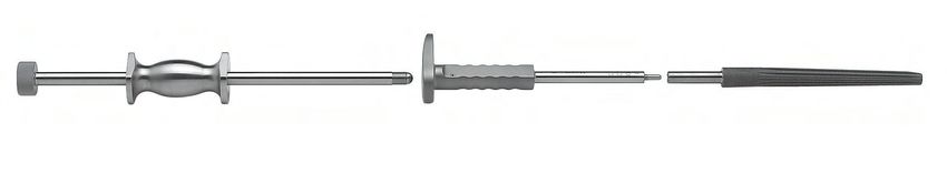
Schaftextraktion Stem Removal
Sollte es intraoperativ oder im Falle einer Revisionsope- If the MP ™ Stem needs to be removed intraopera-
ration erforderlich sein, den MP® Schaft zu entfernen, tively, or in a revision procedure, the Stem Inserter is
Indikationen/Kontraindikationen
wird das Einsetzinstrument auf den liegenden Schaft
Indications/Contraindications
mounted on the seated MP ™ Stem and connected
montiert und mit der Stange mit Wurfhammer ver- with the Threaded Rod with Slaphammer.
schraubt.
By applying measured blows of the Slaphammer
Durch dosierte Schläge des Wurfhammers gegen den
oberen Anschlag kann der MP® Schaft sicher aus dem against the upper stop on the Threaded Rod, the MP ™
Markkanal herausgetrieben werden. Stem can be safely driven out of the medullary canal.
Operationstechnik
Surgical Technik
Stange mit
Wurfhammer
Threaded Rod
with Slaphammer
Zur Instrumenten-Reinigung
Zusätzliche Instrumente
Additional Instruments
wird der Innenstab mit Gewinde durch
Lösen der Innensechskant-Schraube mittels
Sechskantschraubendreher 10-5373 (SW 2,5 mm)
aus dem Einsetzinstrument entfernt.
To clean the instrument, the inner threaded bar
is removed from the Stem Inserter by loosening
the hex screw with Hex Screwdriver
10-5373 (hex 2.5 mm).
Einsetzinstrument
für Schäfte
Stem Inserter
Accessories
Zubehör
MP ® Schaft
MP ™ Stem
Literature
Literatur
| 19081043 Link Inhalt KORRI 27.06.2008 9:10 Uhr Seite 20
Zusätzliche Instrumente - Zubehör
Zusätzliche Instrumente Additional Instruments
(nicht im Instrumentarium enthalten) (not included in Instrument Set)
Klingenmeißel mit Scheide, 250 mm
Guided Osteotome, 250 mm
Art-Nr. / Breite / Nutzlänge /
Item No. Width effective Length
mm mm
65-1700/20 20 65
65-1700/25 25 65
Zubehör Accessories
Röntgenschablonen für MP ®-Rekonstruktionsprothesen X-ray Templates for MPTM Reconstruction Prostheses
110 % natürlicher Größe, Konus 12/14 mm 110 % of actual size, Taper 12/14 mm
Satz à 7 Blatt Set of 7 sheets
(Röntgenschablonen 120 % natürlicher Größe auf Anfrage erhältlich)
(X-ray Templates 120 % of actual size available upon request)
Art.-Nr. CCD-Winkel Kopf-Ø Halslänge für Schaftlänge Satz
Item No. CCD Angle Head-Ø Neck Length for Stem Length Unit
mm
175-870/02 126° 32 mm kurz/short (S) 160 7 Blatt / 7 Sheets
175-870/05 135° 32 mm kurz/short (S) 160 7 Blatt / 7 Sheets
175-870/08 126° 32 mm mittel/medium (M) 180 7 Blatt / 7 Sheets
175-870/11 135° 32 mm mittel/medium (M) 180 7 Blatt / 7 Sheets
175-870/14 126° 32 mm lang/long (L) 210 - 330 7 Blatt / 7 Sheets
175-870/17 135° 32 mm lang/long (L) 210 - 330 7 Blatt / 7 Sheets
20 |081043 Link Inhalt KORRI 27.06.2008 9:10 Uhr Seite 21
Systembeschreibung
System Description
Additional Instruments - Accessories
63-4300/02 63-4300/02
Titan Cerclageband mit Schloss Titanium Cerclage Band with Lock
Material: Titan, 5,8 mm breit, 240 mm Material: Titanium, 5,8 mm wide, 240 mm
Indikationen/Kontraindikationen
Indications/Contraindications
Das Titan Cerclageband n. Thabe bietet eine effektive The Thabe Cerclage Band offers an efficient and easy
und leicht handhabbare Methode bei der Versorgung von way to treat fractures of the femur. Compared to wire
Frakturen aller Art im Femurbereich. Im Vergleich zu cerclage systems, the wide contact surface of the
Drahtcerclagen wird durch die breitflächige Kontaktfläche band distributes compression forces evenly over a
der Bandcerclage der Druck über eine größere Fläche wide area and prevents cutting into the bone. The
verteilt und ein Einschneiden der Cerclage in den corrugated portion of the cerclage band preserves the
Knochen verhindert. Der gewellte Abschnitt des periosteal blood supply, essential to the revitalization
Operationstechnik
Surgical Technik
Cerclagebandes schont die periostale Blutversorgung. of fracture fragments or bone transplants.
Dies ist wichtig für die Revitalisierung von Frakturstücken Titanium is biocompatible, allowing the cerclage to
oder von Transplantatknochen. remain in the body for longer.
Titan ist biokompatibel und erlaubt ein längeres
Verbleiben der Cerclage im Körper.
Indications
Indikationen • Post-traumatic fractures
• Femurfrakturen nach Trauma • Refixation after trochanteric osteotomies
• Knochenfixierung nach Trochanterosteotomien • Shaft fractures in primary or revision arthroplasty
• Schaftfrakturen bei Primär- oder Revisions-TEP • Fixation of bone transplants
• Fixierung von Knochentransplantaten
Zusätzliche Instrumente
Additional Instruments
Osteosynthese-Instrumentarium zum Osteosynthesis Instrument Set for
Titan Cerclageband n. Thabe Thabe Titanium Cerclage Band
63-4300/05
Instrumentarium für Cerclage n. Thabe, komplett
Instrument Set for Thabe Cerclage, complete
bestehend aus / consisting of:
St./Qty.
05-1000/01
Kleincontainer K1, 460 x 190 x 92 mm
K1 Small Container, 460 x 190 x 92 mm 1
63-4300/11
Siebeinsatz, leer, 415 x 175 x 35 mm
Tray, empty, 415 x 175 x 35 mm 1
Accessories
63-4300/19
Zubehör
Cerclageband-Umführungsinstrument
Innenradius 40 mm, 290 mm
Cerclage Band Guide, curve 40 mm, 290 mm 1
63-4300/20
Cerclageband-Umführungsinstrument
Innenradius 50 mm, 300 mm
Cerclage Band Guide, curve 50 mm, 300 mm 1
63-4300/40
Cerclageband-Spanngerät
Cerclage Band Tightener 1
175-600
Sechskantschraubendreher, SW 3,0 mm, 230 mm
Hex Screwdriver, hex 3.0 mm, 230 mm 1 Weitere Informationen zur Handhabung des
Literature
Literatur
64-4300/30 Cerclagebands auf Anfrage.
Cerclage-Spannzange, mit Zahn, 170 mm More information on using the Cerclage Band is
Cerclage Band Pliers, with tooth, 170 mm 1 available on request.
| 21Sie können auch lesen