SERIES 80 SERIES 80 - GISMA Steckverbinder GmbH
←
→
Transkription von Seiteninhalten
Wenn Ihr Browser die Seite nicht korrekt rendert, bitte, lesen Sie den Inhalt der Seite unten
SERIES 80

SERIES 80

PRODUKTKATALOG
DRUCKAUSGEGLICHENE, ÖLGEFÜLLTE
ELEKTRISCHE STECKVERBINDER FÜR
UNTERWASSERSTECKUNGEN

PRODUCT CATALOGUE
OIL FILLED PRESSURE BALANCED
ELECTRICAL CONNECTORS FOR
DEEP SEA MATING

                                                                     Leinestraße 25
                                                              D-24539 Neumünster
                                                        Tel. +49 - 4321 - 98 35 - 30
                                                       Fax +49 - 4321 - 98 35 - 55
                                                         www.gisma-connectors.de
                                                E-Mail: info@gisma-connectors.de
 Catalogue series 80 Revision H - 07/2021   1             www.gisma-connectors.de
SERIES 80

FIRMENPORTRAIT                                                      COMPANY PROFILE

GISMA ist heute einer der führenden Hersteller von                  Today GISMA is one of the leading manufacturers of high-
elektrischen, Lichtwellenleiter- und Hybrid-Steckverbindungen       performance electrical, fibre-optical and hybrid underwater
für die Meerestechnik.                                              connectors.

Grundlagen dieses Erfolges sind:                                    The success of GISMA is based on:
Ÿ ein hoher Qualitätsstandard nach DIN ISO 9001 mit                 Ÿ a high quality management system meeting the
   DNV-GL-Zertifikat                                                    requirements of DIN ISO 9001 with DNV-GL certificate
Ÿ konsequent auf die Kundenbedürfnisse zugeschnittene               Ÿ consistency in meeting the needs of the customer
   Produkte                                                         Ÿ short and reliable delivery times
Ÿ kurze und zuverlässige Lieferzeiten                               Ÿ various services ranging from individual customer advice
Ÿ vielfältige Serviceleistungen von individueller Kunden-             to the delivery of fully-tested, terminated and pressure
   beratung bis zur Lieferung von verkabelten und                     tested cable assemblies
   druckgeprüften Komponenten

Um flexibel auf Kundenwünsche reagieren zu können, fertigt           Maximum flexibility is assured by more than 95% in-house-
GISMA mehr als 95% der Produkte im eigenen Haus.                    production.
Mit einem eigenen Werkzeugbau und hochmodernen                      Special orders are carried out quickly and efficiently using the
computergesteuerten Maschinen in der Fertigung, sowie einer         own computer-aided design department, tooling and
computerunterstützten Konstruktion lassen sich auch                 ultramodern computer controlled machines for production.
Sonderwünsche schnell realisieren.
GISMA Steckverbinder werden weltweit im Bereich der                 Worldwide GISMA connectors are applied in naval
Marinetechnik, Offshore-Industrie, Industrie, Forschung und          technology, offshore industry, industry, research and
erneuerbaren Energien eingesetzt.                                   renewable energy.

GISMA bietet mit Kontaktzahlen von 1-265, Betriebs-                 GISMA offers an extensive family of standard connectors with
spannungen bis 12 kV und Strömen bis 1.000 A in 18                  contact numbers from 1-265, voltages up to 12 kV and current
Baureihen ein umfassendes Programm von Standardsteck-               ratings up to 1,000 A in 18 different series.
verbindern.
Alle marktgängigen Lichtwellenleiter in Single- oder                All types of optical fibres, both single- and multi-mode can be
Multimode-Technik können mit GISMA Steckverbindern                  assembled with GISMA connectors.
konfektioniert werden.

Abnahmezertifikate von allen bekannten Prüforganisationen            Certificates of approval from well known test organisations
wie TÜV (Technischer Überwachungsverein) und DNV-GL                 such as TÜV (Technical Supervision Association) and
sind gegen Aufpreis lieferbar.                                      DNV-GL etc. are available at extra charge.

Catalogue series 80 Revision H - 07/2021                        2                                       www.gisma-connectors.de
SERIES 80
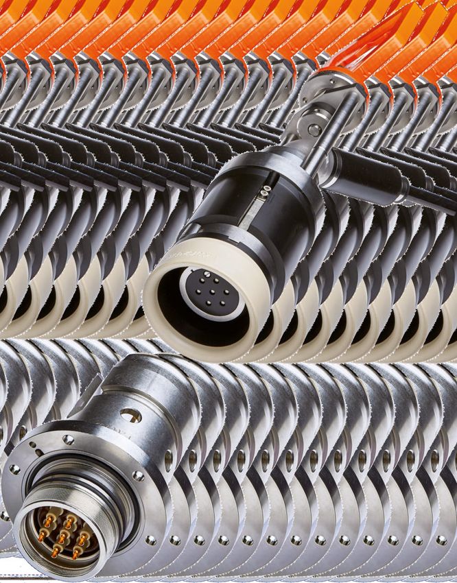
GISMA BAUREIHE 80 GISMA SERIES 80
Druckausgeglichene, ölgefüllte elektrische Steckverbinder für Oil filled pressure balanced electrical connectors for deep sea
Unterwassersteckungen mating
Inhalt: Content:
Seite 2 Firmenportrait Page 2 Company profile
Seite 3 Inhaltsverzeichnis Page 3 Table of content
Seite 4-5 Produktmerkmale Baureihe 80 Page 4-5 Product characteristics series 80
Seite 6 Gehäuseübersicht ROV/Taucher Page 6 Shell styles ROV/diver
Seite 7 Gehäuseübersicht Stab Plate Page 7 Shell styles stab plate
Seite 8 Schnittdarstellung ROV/Taucher Page 8 Sectional view ROV/diver
Seite 9 Schnittdarstellung Stab Plate Page 9 Sectional view stab plate
Seite 10 Polbilder Page 10 Contact arrangements
Seite 11 Technische Daten Page 11 Technical features
Seite 12 Elektrische Daten Page 12 Electrical features
Seite 13 Abmessungen Flanscheinbaudosen Page 13 Dimensions flange receptacles
Seite 14 Abmessungen Stecker für ROV/Taucher Page 14 Dimensions plugs for ROV/diver
Seite 15 Abmessungen Stecker Stab Plate Page 15 Dimensions plugs for stab plate
Seite 16 Abmessungen Durchführungen Page 16 Dimensions penetrators
Seite 17 Abmessungen Schlauchanschluss- Page 17 Dimensions hose connection
adapter 90° adapters 90°
Seite 18 Abmessungen Schlauchanschluss- Page 18 Dimensions hose connection
adapter gerade adapters straight
Seite 19 Abmessungen Schlauchfittinge Page 19 Dimensions hose fittings
Seite 20 Abmessungen Vergussendgehäuse gerade Page 20 Dimensions moulding endbells straight
Seite 21 Abmessungen Vergussendgehäuse 90° Page 21 Dimensions moulding endbells 90°
Seite 22 Abmessungen Vergussendgehäuse 45° Page 22 Dimensions moulding endbells 45°
Seite 23 Abmessungen Schutzkappen ROV/Taucher Page 23 Dimensions protective caps ROV/diver
Seite 24 Abmessungen Schutzkappen Stab Plate Page 24 Dimensions protective caps stab plate
Seite 25 Abmessungen POM-Schutzkappen Page 25 Dimensions plastic protective caps
Seite 26 Abmessungen Taucher-Griffe Page 26 Dimensions diver handles
Seite 27 Abmessungen D-Griffe Page 27 Dimensions D-handles
Seite 28 Abmessungen Fishtail-Griffe Page 28 Dimensions fishtail-handles
Seite 29 Bestellbeispiel Page 29 Ordering example
Seite 30 Einbaudosen und Stecker Page 30 Receptacles and plugs
Seite 31 Vergussendgehäuse Page 31 Endbells
Seite 32 Griffe und Zubehör Page 32 Handles and equipment
Seite 33 Schutzkappen Page 33 Protective caps
Seite 34 Schlauchadapter Page 34 Hose adapters
Seite 35 Schlauchfittinge Page 35 Hose fittings
Mit Erscheinen dieses Kataloges verlieren alle früheren This catalogue supersedes all previous editions.
Kataloge ihre Gültigkeit.
Produktänderungen behalten wir uns vor ohne zur GISMA reserves the right to modify products because of
Ersatzlieferung älterer Ausführungen verpflichtet zu sein. technical improvements and development without prior notice.
Abmessungen dienen nur zu Informationszwecken und Dimensions are given for information purposes only and must
müssen von GISMA bestätigt werden. be confirmed by GISMA.
Dieser Katalog steht auch als PDF-Datei zur Verfügung. This catalogue is available as pdf-file as well.
Catalogue series 80 Revision H - 07/2021 3 www.gisma-connectors.de
SERIES 80

PRODUKTMERKMALE BAUREIHE 80                                         PRODUCT CHARACTERISTICS SERIES 80

Die Haupteinsatzgebiete sind:                                       The main fields of application are:
Ÿ Unterwasser-Stab-Plates                                           Ÿ subsea stab plates
Ÿ Unterwasser-Verteiler                                             Ÿ subsea trees
Ÿ ROV-steckbare Anwendungen                                         Ÿ ROV mateable applications

Der ölgefüllte, druckausgeglichene elektrische Steckverbinder       The fluid filled pressure balanced electrical connector series
der Baureihe 80 ist speziell für Unterwassersteckungen in der       80 is specially designed for deep sea mating.
Tiefsee konstruiert.
Durch ein Druckausgleichsystem werden geringe, gleich-              Constant and low mating forces minimize the material stress
bleibende Steckkräfte und eine verringerte Materialbelastung        at all designed pressure and depth capabilities.
der Dichtungen erreicht.

Die Konstruktion erfüllt höchste Ansprüche an die Zuver-            The high quality of series 80 is based on a very reliable
lässigkeit durch ein aufwendiges Dichtsystem in Zusammen-           sealing system, a pressure balanced system and the new
wirkung mit dem Druckausgleichsystem und dem von GISMA              GISMA flushing device.
neu entwickelten Spülsystem.

Konstruktionsmerkmale Baureihe 80:                                  Design features series 80:
Ÿ unter Wasser steckbar                                             Ÿ underwater mateable
Ÿ gleichbleibende Steckkräfte unabhängig von der                    Ÿ constant mating forces at every water depth
  Wassertiefe                                                       Ÿ pressure balanced plug
Ÿ druckausgeglichener Stecker                                       Ÿ flushing device for an internal cleaning process during
Ÿ Spülsystem für eine Selbstreinigung während der                     mating
  Steckung                                                          Ÿ high performance materials (FVMQ, PEEK, titanium) for
Ÿ hochwertige Materialien (FVMQ, PEEK, Titan) für eine                long term use
  lange Lebensdauer                                                 Ÿ modular design system
Ÿ modulares Grundprinzip                                            Ÿ new maintenance features
Ÿ neue Wartungsmöglichkeiten                                        Ÿ design life time 25 years
Ÿ ausgelegt auf eine Lebensdauer von 25 Jahren                      Ÿ different keyways available
Ÿ unterschiedliche Keyways lieferbar                                Ÿ insulation distance according to DIN EN 60664-1
Ÿ Luft- und Kriechstrecken gemäß DIN EN 60664-1                       (VDE 0110-1)
  (VDE 0110-1)

Konstruktionsmerkmale Baureihe 80 Einbaudose:                       Design features series 80 receptacle:
Ÿ längswasserdichtes Kontaktdesign mit 2 voneinander                Ÿ longitudinally sealed contact design with 2 independent
  unabhängigen doppelten O-Ring-Dichtungen (insgesamt 4               double O-ring-seals (4 O-rings in total)
  O-Ringe)                                                          Ÿ gold plated PEEK isolated beryllium copper pin contact
Ÿ vergoldeter, PEEK-isolierter Beryllium-Kupfer-Stiftkontakt        Ÿ shock- and pressure resistant epoxy casting at the
Ÿ schock- und druckdichter Schottverguß an der Einbau-                receptacle‘s rear
  dosenrückseite                                                    Ÿ receptacles are designed for air and oil-filled junction
Ÿ die Einbaudosen können in öl- oder luftgefüllten Gehäusen           boxes
  eingebaut werden                                                  Ÿ scoop proof design
Ÿ Scoop Proof Design

Catalogue series 80 Revision H - 07/2021                        4                                       www.gisma-connectors.de
SERIES 80

PRODUKTMERKMALE BAUREIHE 80                                      PRODUCT CHARACTERISTICS SERIES 80

Konstruktionsmerkmale Baureihe 80 Stecker:                       Design features series 80 plug:
Ÿ 3 Verschlußklinken mit Sicherheitsfeder                        Ÿ 3 locking clamps with an overall safety spring
Ÿ diverse Griffausführungen erhältlich                            Ÿ various handles (bars) available
Ÿ doppeltes Membran-System aus FVMQ                              Ÿ strong double membrane sealing system made of FVMQ
Ÿ doppelte FVMQ-O-Ring-Dichtung                                  Ÿ double FVMQ O-ring seals
Ÿ 16 mm lange Eingangsdichtung für jeden Kontakt                 Ÿ 16 mm long entry gasket for each contact
Ÿ speziell konstruierter Pilotstift, der den Druck in der        Ÿ special design shuttle pin to reduce compression set in the
  vorderen Lippe während Lagerung reduziert                        front gasket during storage
Ÿ Pilot-Stift aus PEEK                                           Ÿ shuttle pin made of PEEK
Ÿ verschiedene Endgehäuse lieferbar                              Ÿ various endbells and hose tube adapters available

Folgende weiterführende Dokumente sind auf Anfrage               The following complementary documents are available on
erhältlich:                                                      request:
Ÿ GISMA Handhabungsanweisung HI-2007-001                         Ÿ GISMA handling instructions HI-2007-001
Ÿ GISMA Drehmoment-Übersicht                                     Ÿ GISMA torque overview
Ÿ GISMA Verkabelungsanleitung                                    Ÿ GISMA cabling instructions
Ÿ GISMA Werkzeugliste                                            Ÿ GISMA tool list

Für weitere Informationen stehen wir Ihnen gerne jederzeit       For further information please feel free to contact us.
zur Verfügung.

Catalogue series 80 Revision H - 07/2021                     5                                        www.gisma-connectors.de
SERIES 80

GEHÄUSEÜBERSICHT - ROV UND TAUCHER                               SHELL STYLES - ROV AND DIVER

Folgende Gehäuse sind erhältlich:                                Following shell styles are available:

Vergussendgehäuse, gerade *         Einbaudose mit Flansch       ROV-/Taucher-Stecker               Vergussendgehäuse
moulding endbell, straight *        flange receptacle             ROV-/diver plug                    45° abgewinkelt
                                                                                                    moulding endbell
                                                                                                    45° angled

                                                                          Vergussendgehäuse
                                                                          90° abgewinkelt
                                                                          moulding endbell
Schlauchadapter und -fitting, gerade                                       90° angled
hose adapter and fitting, straight

                                                                          POM-Schutzkappe
POM-Schutzkappe für Stecker                                               für Einbaudose
plastic protective cap for plug                                           plastic protective cap
                                                                          for flange receptacle

Griffe für ROV-/Taucher-Stecker und                               Schlauchadapter und - fitting
druckwasserdichte Schutzkappe                                    90° abgewinkelt
handles for ROV-/diver plug and                                  hose adapter and fitting
pressure watertight cap                                          90° angled

  Taucher-Griff
  diver handle

                                                                 druckwasserdichte ROV-/Taucher-Schutzkappe
                                                                 für Einbaudose
  D-Griff                                                         pressure watertight cap ROV-/diver
  D-handle                                                       for flange receptacle

  Fishtail-Griff
  fishtail handle

* abgewinkelte Endgehäuse auf Anfrage erhältlich
* angled endbells are available on request

Catalogue series 80 Revision H - 07/2021                     6                                           www.gisma-connectors.de
SERIES 80

GEHÄUSEÜBERSICHT - STAB PLATE                                      SHELL STYLES - STAB PLATE

Folgende Gehäuse sind erhältlich:                                  Following shell styles are available:

Vergussendgehäuse, gerade *         Einbaudose mit Flansch         Stab Plate Stecker               Vergussendgehäuse gerade
moulding endbell, straight *        flange receptacle               stab plate plug                  moulding endbell straight

                                                                            Vergussendgehäuse
                                                                            45° abgewinkelt
                                                                            moulding endbell
                                                                            45° angled
Schlauchadapter und -fitting, gerade
hose adapter and fitting, straight

                druckwasserdichte Stab Plate-Schutzkappe
                für Einbaudose
                                                                                                     Vergussend-
                pressure watertight cap stab plate
                                                                                                     gehäuse 90°
                for flange receptacle
                                                                                                     abgewinkelt
                                                                                                     moulding
                                                                                                     endbell
                                                                                                     90° angled

                 POM-Schutzkappe                                           Schutzkappe
                 für Stecker                                               für Einbaudose              Schlauchadapter und
                 plastic protective                                        protective cap              -fitting, gerade
                 cap for plug                                              for flange receptacle        hose adapter and fitting,
                                                                                                       straight

          Durchführung              Vergussendgehäuse gerade *            Schlauchadapter 90°
          penetrator                moulding endbell straight *           abgewinkelt
                                                                          hose adapter 90° angled

                                                                          Schlauchadapter 60°
                                                                          abgewinkelt
                                                                          hose adapter 60° angled

                                                                                                           Schlauchfitting
                                    Schlauchadapter und -fitting, gerade                                    hose fitting
                                    hose adapter and fitting, straight

* abgewinkelte Endgehäuse auf Anfrage erhältlich
* angled endbells are available on request

Catalogue series 80 Revision H - 07/2021                       7                                           www.gisma-connectors.de
SERIES 80

SCHNITTDARSTELLUNG                                                   SECTIONAL VIEW

Schematische Darstellung eines GISMA Baureihe 80                     Schematic diagram of a GISMA series 80 connector (flange
Steckverbinders (Flanscheinbaudose, Stecker, Endgehäuse              receptacle, plug, endbell and diver handle).
und Taucher-Griff).

                                                                                    Vergussmasse
                                                                                    moulding

                                                                                                                 Formteil
                                                            Taucher-Griff                                         rubber boot
                                                            diver handle
                                                                                                                 Schellenband
                                                                                                                 clamp

                                                Endgehäuseadapter
                                                endbell adapter
                                           Epoxid-Verguss                                                               Kabel
                                           epoxy casting                                                                cable
                                                                                                                Pressmutter
                                                                                                                press nut
                            Lötkontakt
                            soldering contact                                                               konische Halbschalen
                                                                                                            conical clamps
      Membranen für Druckausgleich                                                                Schellenband
      pressure balance membranes                                                                  clamp
 äußerer Keyway für
 Ausrichtung
                                                                            PEEK-Bootseal-Adapter
 outer keyway for
                                                                            PEEK boot seal adapter
 orientation

  16 mm lange
  Front-Dichtung                                                              massiver Adapterring für Griff
  16 mm long                                                                  massive adapter ring for handle
  pin entry gasket
           Keyway
                                                                Verriegelungsklammern
           keyway
                                                                locking clamps
  PEEK Isolierkörper
  PEEK insulator
                                                            Sicherungsfeder
  Lötkontakt
                                                            safety spring
  soldering contact
                                                       PEEK-Zentrierring
                                                       PEEK centering ring
 Epoxid-Verguss
                                                            O-Ring-Dichtung
 epoxy casting
                                                            O-ring sealing
 Einbaudose mit Flansch                          PEEK-Bootseal-Adapter
 receptacle with flange                           PEEK boot seal adapter

Catalogue series 80 Revision H - 07/2021                         8                                    www.gisma-connectors.de
SERIES 80

SCHNITTDARSTELLUNG                                                SECTIONAL VIEW

Schematische Darstellung eines GISMA Baureihe 80                  Schematic diagram of a GISMA series 80 connector (flange
Steckverbinders (Flanscheinbaudose, Stecker, Endgehäuse           receptacle, plug, endbell and D-handle).
und D-Griff).
                                                                                                               D-Griff
                                                                                                               D-handle

                                                Elastomergelenk
                                                rubber joint

                                                                                           Schlauch-Endgehäuseadapter
                                                                                           hose endbell adapter

                                                                                                             Schlauchadapter
                                                                                                             hose adapter

                           Lötkontakt                                                                               Schlauch
                           soldering contact                                                                        hose
    Membranen für Druckausgleich
    pressure balance membranes

äußerer Keyway für
Ausrichtung
                                                                        PEEK-Bootseal-Adapter
outer keyway for
                                                                        PEEK boot seal adapter
orientation

16 mm lange
Front-Dichtung                                                             massiver Adapterring für Griff
16 mm long                                                                 massive adapter ring for handle
pin entry gasket
         Keyway
                                                            Verriegelungsklammern
         keyway
                                                            locking clamps
PEEK Isolierkörper
PEEK insulator
                                                       Sicherungsfeder
Lötkontakt
                                                       safety spring
soldering contact
                                                     PEEK-Zentrierring
                                                     PEEK centering ring
Epoxid-Verguss
                                                       O-Ring-Dichtung
epoxy casting
                                                       O-ring sealing
Einbaudose mit Flansch                         PEEK-Bootseal-Adapter
receptacle with flange                          PEEK boot seal adapter

Catalogue series 80 Revision H - 07/2021                      9                                      www.gisma-connectors.de
SERIES 80

POLBILDER                                                     CONTACT ARRANGEMENTS

Die Steckverbinder der Baureihe 80 sind bestückt mit          Series 80 connectors are fitted with Ø 2 mm, Ø 3 mm,
Ø 2 mm, Ø 3 mm, Ø 6 mm, Ø 8 mm oder Ø 10 mm                   Ø 6 mm, Ø 8 mm or Ø 10 mm contacts.
Kontakten.
                            Kontaktanordnungen (Frontansicht Einbaudose / Rückseite Stecker)
                               contact arrangements (front view receptacle / rear view plug)

 Größe                      Kontakt-Ø 3 mm                                       Power-Kontake
  size                      contact-Ø 3 mm                                       power contacts

    1      04

    2      07

    3      12                                                  04

                                                                                                      4 x Ø 6 mm

    4      19

    6                                                          04

                                                                                                      4 x Ø 10 mm

* = Sonderpolbilder - technische Daten bitte gesondert anfragen
* = special contact arrangements - technical data on request

Catalogue series 80 Revision H - 07/2021                 10                                     www.gisma-connectors.de
SERIES 80
POLBILDER CONTACT ARRANGEMENTS
Kontaktanordnungen (Frontansicht Einbaudose / Rückseite Stecker)
contact arrangements (front view receptacle / rear view plug)
Größe LWL Hybrid
size f/o hybrid
4 04 04 06
2 x f/o 2 x Ø 8 mm
2 x Ø 2 mm 4 x Ø 3 mm
1 9
2
10 13 8
5 13 3
11 12 7
4
6
5
4 x f/o
max. 50 bar 9 x Ø 3 mm
* = Sonderpolbilder - technische Daten bitte gesondert anfragen
* = special contact arrangements - technical data on request
Catalogue series 80 Revision H - 07/2021 11 www.gisma-connectors.deSERIES 80
TECHNISCHE DATEN TECHNICAL FEATURES
Für alle Sonderdesigns der Baureihe 80 beachten Sie bitte die For all series 80 special designs, please pay attention to the
individuellen Datenblätter in ihrer jeweils gültigen Ausgabe. individual data sheets and follow the valid issues.
max. Betriebsdruck bei 20 °C max. operating pressure range at 20 °C
max. 300 bar max. 300 bar
Prüfdruck test pressure
450 bar 450 bar
Betriebstemperatur operating temperature
-5 °C bis +40 °C -5 °C up to +40 °C
Lagertemperatur storage temperature
-18 °C bis +50 °C -18 °C up to +50 °C
Verriegelung locking
Push-Pull-Verriegelung oder push pull locking system or
integrationsfähig in Steckvorrichtung stab plate integration
Standard-Gehäusematerial standard-shell material
Titan Grade V titanium grade V
Edelstahl AISI 316 L stainless steel AISI 316 L
andere Materialien auf Anfrage other materials on request
Steckerkodierung special orientation
Keyways keyways
Kabelanschluss cable connection
Verguß-Technik moulding technique
ölgefüllte Schläuche oil-filled tubes
Ø 3 mm Größe / size 1 ~ 250 N
Steck- und Entriegelungskräfte ROV Ø 3 mm Größe / size 2 ~ 430 N
mating and demating forces ROV Ø 3 mm Größe / size 3 ~ 650 N
Ø 3 mm Größe / size 4 ~ 900 N
Ø 3 mm Größe / size 1 ~ 200 N
Ø 3 mm Größe / size 2 ~ 350 N
Steck- und Entriegelungskräfte Stab plate
Ø 3 mm Größe / size 3 ~ 550 N
mating and demating forces stab plate
Ø 3 mm Größe / size 4 ~ 750 N
Ø 10 mm ~ 1.200 N
Catalogue series 80 Revision H - 07/2021 12 www.gisma-connectors.deSERIES 80
ELEKTRISCHE DATEN ELECTRICAL FEATURES
Die GISMA Steckverbinder der Baureihe 80 sind mit GISMA connectors series 80 are assembled variable with
elektrischen Kontakten Ø 2 mm, Ø 3 mm, Ø 6 mm, Ø 8 mm electrical contacts Ø 2 mm, Ø 3 mm, Ø 6 mm, Ø 8 mm oder
oder Ø 10 mm bestückt. Ø 10 mm.
Siehe dazu auch die GISMA Anweisungen für Handhabung Refer to the GISMA instructions for handling or cabling.
und Verkabelung.
Kontakt-Ø Ø 2 mm 3)
Ø 3 mm 3)
Ø 6 mm 3)
Ø 8 mm 3)
Ø 10 mm 3)
contact-Ø Ø 2 mm 3)
Ø 3 mm 3)
Ø 6 mm 3)
Ø 8 mm 3)
Ø 10 mm 3)
max. Anschlussquerschnitt
1,5 mm² 2,5 mm² 10 mm² 6 mm² 95 mm²
max. cross sectional area
max. Betriebsspannung 1000 VAC 1)
630 VDC 1) 1.000 VDC 1) 3000 VDC 1) 6.600 VAC 1)
max. operating voltage 1500 VDC 1)
< 30 °C 2):
max. 90 A (50 mm²)
2 - 2,5 mm²: max. 90 A (75 mm²)
max. 20 A 2) max. 100 A (95 mm²)
Strombelastbarkeit pro Kontakt
max. 25 A max. 55 A max. 40 A
working current per contact
> 2,5 mm²: < 10 °C 2):
max. 30 A 2) max. 80 A (50 mm²)
max. 100 A (75 mm²)
max. 110 A (95 mm²)
Isolationswiderstand
> 10 GΩ > 10 GΩ > 10 GΩ > 10 GΩ > 10 GΩ
insulation resistance
Prüfspannung
2500 VDC 5000 VDC 5000 VDC 7000 VDC 15.000 VDC
test voltage
Kontaktübergangswiderstand
< 10 mΩ < 4 mΩ < 4 mΩ < 4 mΩ < 4 mΩ
contact resistance
Steckzyklen
min. 50 min. 200 min. 200 min. 200 min. 100
mating cycles
1)
Luft- und Kriechstrecken gemäß DIN EN 60664-1 (VDE 0110-1) Tabelle 4/Verschmutzungsgrad 3 I
Insulation distance according to DIN EN 60664-1 (VDE 0110-1) chart 4/class 3 I
2)
In Abhängigkeit von der Umgebungstemperatur ist die Gesamtverlustleistung zur vorgegebenen max. Betriebstemperatur zu beachten
Depending on the ambient temperature the overall power has to fit with the max. operating temperature
3)
vergoldet
gold plated
Catalogue series 80 Revision H - 07/2021 13 www.gisma-connectors.deSERIES 80
LWL-DATEN FIBRE-OPTICAL FEATURES
Die GISMA Baureihe 80 Steckverbinder können mit Single- GISMA series 80 connectors can be assembled with single- or
oder Multimode-Fasern konfektioniert werden. multimode fibres.
Kontakt-Typ
Multimode 62,5 µm Multimode 50 µm Singlemode 9 µm
contact type
Dämpfung je Übergangsstelle < 0,5 dB < 0,5 dB < 0,5 dB
attenuation per contact point < 0.5 dB < 0.5 dB < 0.5 dB
Catalogue series 80 Revision H - 07/2021 14 www.gisma-connectors.deSERIES 80
ABMESSUNGEN DIMENSIONS
Einbaudosen mit Flansch flange receptacles
*
Größe 1-4: X = 60° (6x) / Ø H Y = für M6
Größe 6: X = 90° (4x) / Ø H Y= für M10
Size 1-4: X = 60° (6x) / Ø H Y = for M6
Size 6: X = 90° (4x) / Ø H Y = for M10
Größe Kontaktanordnung
A ØB C D E F G ØH ØJ Ø K1
size contact arrangement
4 Kontakte
1 M47x1 48 61,6 113,3 22,5 11,2 148 76 89 52,1
4 contacts
7 Kontakte
2 M55x1 57 71,6 114,1 22 11,2 149 86 99 62,1
7 contacts
12 Kontakte
3 M62x1 63,5 80,7 115,8 22 11,1 154 93 106 68,1
12 contacts
4, 6 oder 19 Kontakte
4 M75x1 77 100 121,3 21 11,1 159 113 129,5 80,2
4, 6 or 19 contacts
4 Kontakte
6 M112x2 114,5 149,4 169 79,4 18,7 290,4 185 210 122,2
4 contacts
Catalogue series 80 Revision H - 07/2021 15 www.gisma-connectors.deSERIES 80
ABMESSUNGEN DIMENSIONS
Stecker vorbereitet für ROV-/Taucher-Griff plugs prepared for ROV-/diver handle
Größe Kontaktanordnung
ØA ØB ØC D E F
size contact arrangement
4 Kontakte
1 55 86,5 80 169 204 M48x2
4 contacts
7 Kontakte
2 68 101 93 165 200 M60x1,5
7 contacts
12 Kontakte
3 76 109 103 166 200 M68x1,5
12 contacts
19 Kontakte
4 91,5 124 122 166 201 M85x2
19 contacts
6 - - - - - - -
Catalogue series 80 Revision H - 07/2021 16 www.gisma-connectors.deSERIES 80
ABMESSUNGEN DIMENSIONS
Stecker für Stab-Plate-Integration plugs for stab plate integration
60° (6x)
Größe Kontaktanordnung
ØA ØB C D E F ØG H
size contact arrangement
4 Kontakte
1 52,5 92 127,5 14 171 79 6,4 M48x2
4 contacts
7 Kontakte
2 65,5 102 125,5 14 171 89 6,4 M60x1,5
7 contacts
12 Kontakte
3 73,5 110 125,5 14 171 98 6,4 M68x1,5
12 contacts
4, 6 oder 19 Kontakte
4 89,5 129,5 125,5 14 173 118 6,6 M85x2
4, 6 or 19 contacts
4 Kontakte
6 139 200 258 18 283,2 180 10,5 134x1,5
4 contacts
Catalogue series 80 Revision H - 07/2021 17 www.gisma-connectors.deSERIES 80
ABMESSUNGEN DIMENSIONS
Durchführungen penetrators
für M6 (6x)
for M6 (6x)
60° (6x)
Größe Kontaktanordnung
ØA ØB ØC D E F G ØH ØJ Ø K1
size contact arrangement
4 Kontakte
1 55 86,5 80 169 204 11,1 104,8 89 76 52,1
4 contacts
7 Kontakte
2 68 101 93 165 200 11,1 100,8 99 86 62,1
7 contacts
12 Kontakte
3 76 109 103 166 200 11,1 105,4 106 93 68,1
12 contacts
4 - - - - - - - - - - -
6 - - - - - - - - - - -
Catalogue series 80 Revision H - 07/2021 18 www.gisma-connectors.deSERIES 80
ABMESSUNGEN DIMENSIONS
Schlauchanschlussadapter hose connection adapters
90° abgewinkelt 90° angled
D
ØA
C
E
90
°
B
Größe
ØA B C D E
size
1 52,2 M25x1 M48x2 94,6 99,1
2 - - M60x1,5 - -
3 - - M68x1,5 - -
4 89,2 M32x1,5 M85 x 2 108,3 127,1
6 - - - - -
Catalogue series 80 Revision H - 07/2021 19 www.gisma-connectors.deSERIES 80
ABMESSUNGEN DIMENSIONS
Gerade Schlauchanschlussadapter für straight hose connection adapters for
Ÿ Stecker Ÿ plugs
Ÿ Einbaudosen Ÿ receptacles
Größe Größe
ØA B C D ØA B C D
size size
1 52,2 89 M48x2 M25x1,5 1 60,3 93 M47x1 M25x1,5
2 65,2 - M60x1,5 M25x1,5 2 71 93 M55x1 M25x1,5
3 73,2 - M68x1,5 M32x1,5 3 - - M62x1 M32x1,5
4 89,2 - M85x2 M42x2 4 - - M75x1 M32x1,5
6 139 - M134x1,5 M62x3 6 - - M112x2 M32x1,5
Catalogue series 80 Revision H - 07/2021 20 www.gisma-connectors.deSERIES 80
ABMESSUNGEN DIMENSIONS
Schlauchfittinge hose fittings
C
SW E
AF E
Größe SW E
A B ØC ØD
size AF E
1 M25x1,5 71,7 22,6 12,7 mm / 1/2 " 29
2 M25x1,5 71,7 22,6 12,7 mm / 1/2 " 29
3 M32x1,5 82,3 30,2 19,0 mm / 3/4 " 36
4 M42x2 90,8 38,1 25,4 mm / 1 " 46
6 M62x3 118,6 51,8 38,0 mm / 1 1/2 " 59
Catalogue series 80 Revision H - 07/2021 21 www.gisma-connectors.deSERIES 80
ABMESSUNGEN DIMENSIONS
Vergussendgehäuse gerade moulding endbells straight
Größe
ØA ØB max. Ø C D E F
size
1 52,2 36,5 15 145,9 10 M48x2
2 65,2 45 23,5 130,9 11,7 M60x1,5
3 73,2 50 24 138,1 11,7 M68x1,5
4 89,2 55 19 186,2 11,7 M85x2
6 139 86 51,2 331,1 17 -
Catalogue series 80 Revision H - 07/2021 22 www.gisma-connectors.deSERIES 80
ABMESSUNGEN DIMENSIONS
Vergussendgehäuse moulding endbells
90° abgewinkelt 90° angled
Größe
ØA ØB max. Ø C D E F
size
1 52,2 36,5 15 83,2 208,6 M48x2
2 65,2 45 23,5 85 213,1 M60x1,5
3 73,2 50 25 92,4 221,1 M68x1,5
4 89,2 45 23,5 101,4 225,1 M85x2
6 139 - - - - -
Catalogue series 80 Revision H - 07/2021 23 www.gisma-connectors.deSERIES 80
ABMESSUNGEN DIMENSIONS
Endgehäuse endbells
45° abgewinkelt 45° angled
Größe
ØA ØB max. Ø C D E F
size
1 52,2 36,5 15 146,3 139,3 M48x2
2 65,2 45 23,5 152,9 150,8 M60x1,5
3 73,2 45 23,5 157,8 154,8 M68x1,5
4 89,2 45 23,5 157,5 162,8 M85x2
6 139 - - - - -
Catalogue series 80 Revision H - 07/2021 24 www.gisma-connectors.deSERIES 80
ABMESSUNGEN DIMENSIONS
druckwasserdichte ROV-/Taucher-Schutzkappen ROV-/diver pressure watertight caps
für Einbaudose for receptacle
Vorbereitet für: Prepared for:
Ÿ ROV-Griff Ÿ ROV-handle
Ÿ D-Griff Ÿ D-handle
Ÿ Taucher-Griff Ÿ diver handle
Größe
ØA B C
size
1 80 168,9 215,9
2 93 165 212
3 103 165,4 212,1
4 122 165,9 210,3
6 - - -
Catalogue series 80 Revision H - 07/2021 25 www.gisma-connectors.deSERIES 80
ABMESSUNGEN DIMENSIONS
druckwasserdichte Stab Plate-Schutzkappen stab plate pressure watertight caps
für Einbaudose for receptacle
ACHTUNG! Die Montagebohrungen ändern sich je nach ATTENTION! The mounting holes vary according to shell
Gehäusegröße! size!
Lochkreis-Ø F
bore-circle Ø F
für M6*
for M6*
X*
*
Größe 1-4: X = 60° (6x) / Ø G
Größe 6: X = 90° (4x) / Ø G
Size 1-4: X = 60° (6x) / Ø G
Size 6: X = 90° (4x) / Ø G
Größe
ØA ØB C D E ØF ØG
size
1 52,5 92 127,5 14 185,1 79 6,4
2 - - - - - - -
3 - - - - - - -
4 - - - - - - -
6 139 200 258 18 296,6 180 10,5
Catalogue series 80 Revision H - 07/2021 26 www.gisma-connectors.deSERIES 80
ABMESSUNGEN DIMENSIONS
Schutzkappen für protective caps for
Ÿ Stecker Ÿ plugs
Ÿ Einbaudosen Ÿ receptacles
Größe
ØA ØB C ØA B
size
1 55 57,5 124 70 40
2 65 67,5 124 80 40
3 76 76 126 90 40
4 93,3 93,3 126 110 40
6 150,6 99 172 165 50
Catalogue series 80 Revision H - 07/2021 27 www.gisma-connectors.deSERIES 80
ABMESSUNGEN DIMENSIONS
Taucher-Griffe diver handles
Größe
A B ØC
size
1 160,5 100 35
2 221 122 49,5
3 221 122 49,5
4 221 145 49,5
6 - - -
Catalogue series 80 Revision H - 07/2021 28 www.gisma-connectors.deSERIES 80
ABMESSUNGEN DIMENSIONS
Fishtail-Griffe fishtail handles
für ROV-Betätigung for ROV mating
Größe
A B C ØD
size
1 186,5 227,7 112,4 70
2 208,5 227,7 112,4 70
3 208,5 227,7 112,4 70
4 208,5 227,7 112,4 70
6 - - - -
Catalogue series 80 Revision H - 07/2021 29 www.gisma-connectors.deSERIES 80
ABMESSUNGEN DIMENSIONS
D-Griffe D-handles
für ROV-Betätigung for ROV mating
Größe
A B C ØD
size
1 203,5 149 130 70
2 225,5 149 130 70
3 225,5 149 130 70
4 225,5 149 130 70
6 - - - -
Catalogue series 80 Revision H - 07/2021 30 www.gisma-connectors.deSERIES 80
BESTELLBEISPIEL ORDERING EXAMPLE
Baureihe 80 Größe 1 Steckverbinder 4-polig. Series 80 size 1 connector 4 way.
Folgende weiterführende Dokumente sind auf Anfrage The following complementary documents are available on
erhältlich: request:
Ÿ GISMA Handhabungsanweisung HI-2007-001 Ÿ GISMA handling instructions HI-2007-001
Ÿ GISMA Drehmoment-Übersicht Ÿ GISMA torque overview
Ÿ GISMA Verkabelungsanleitung Ÿ GISMA cabling instructions
D-Griff Artikel-Nr.: 80.75.1-00.3.01.0
D-handle part no.: 80.75.1-00.3.01.0
Schlauchfitting mit Gorilla Schlauch
Artikel-Nr.: 80.H.1.25.A13.10.010.00
hose fitting with Gorilla hose
part no.: 80.H.1.25.A13.10.010.00
Endgehäuse 45° abgewinkelt für Stecker
Artikel-Nr.: 80.90.1-45.3.XX.0
endbell 45° angled for plug
part no.: 80.90.1-45.3.XX.0
Schlauchanschlussadapter 90° abgewinkelt für Stecker
Artikel-Nr.: 80.94.1-90.3.A13.0
hose connection adapter 90° angled for plug
part no.: 80.94.1-90.3.A13.0
ROV-/Taucher-Stecker Artikel-Nr.: 80.06.1S04.3.01.0
ROV-/diver plug part no.: 80.06.1S04.3.01.0
Flanscheinbaudose Artikel-Nr.: 80.00.1P04.3.00.0
flange receptacle part no.: 80.00.1P04.3.00.0
Vergussendgehäuse für Einbaudose Artikel-Nr.: 80.80.1-00.3.XX.1
moulding endbell for receptacle part no.: 80.80.1-00.3.XX.1
Schlauchanschlussadapter für Einbaudose
Artikel-Nr.: 80.84.1-00.3.A13.0
hose connection adapter for receptacle
part no.: 80.84.1-00.3.A13.0
Schlauchfitting mit Gorilla-Schlauch
Artikel-Nr.: 80.H.1.25.A13.10.010.00
hose fitting with Gorilla hose
part no.: 80.H.1.25.A13.10.010.00
Catalogue series 80 Revision H - 07/2021 31 www.gisma-connectors.deSERIES 80
BESTELLNUMMERNSCHLÜSSEL REFERENCE NUMBERING SYSTEM
EINBAUDOSEN UND STECKER RECEPTACLES AND PLUGS
8 0 . _ _ . _ . _ . _ _ . _ . _ _ . _
1 2 3 4 5 6 7 8
1 Baureihe 1 Series
2 Gehäuseart 2 Shell style
00 Einbaudose mit Stiftkontakten 00 receptacle with pin contacts
(Standard - ROV, Taucher, Stab Plate) (standard - ROV, diver, stab plate)
06 Stecker mit Buchsenkontakten 06 plug with socket contacts
(Standard - ROV, Taucher) (standard - ROV, diver)
16 Stecker mit Buchsenkontakten 16 plug with socket contacts
(Standard - Stab-Plate) (standard - stab-plate)
3 Gehäusegröße 3 Shell size
1 Größe 1 1 Size 1
2 Größe 2 2 Size 2
3 Größe 3 3 Size 3
4 Größe 4 4 Size 4
6 Größe 6 6 Size 6
4 Kontaktart 4 Contact type
P Stiftkontakt P pin contact
S Buchsenkontakt S socket contact
C Koax-Kontakt C coaxial contact
H Hybrid H hybrid
F LWL F fibre optic
5 Kontaktzahl 5 Contact arrangement
04 4 Kontakte 04 4 contacts
07 7 Kontakte 07 7 contacts
12 12 Kontakte 12 12 contacts
19 19 Kontakte 19 19 contacts
6 Material 6 Material
1 Titan Grade V 1 titanium grade V
3 Edelstahl 1.4404 / 1.4571 3 stainless steel 1.4404 / 1.4571
6 Kunststoff POM 6 plastic POM
7 Sondernummer 7 Special part numbers
8 Keyway-Typ (falls notwendig) 8 Keyway type (if necessary)
W Keyway 110° W Keyway 110°
X Keyway 44° X Keyway 44°
Y Keyway 66° Y Keyway 66°
Z Keyway 88° Z Keyway 88°
Catalogue series 80 Revision H - 07/2021 32 www.gisma-connectors.deSERIES 80
BESTELLNUMMERNSCHLÜSSEL REFERENCE NUMBERING SYSTEM
VERGUSSENDGEHÄUSE MOULDING ENDBELLS
8 0 . _ _ . _ _ _ _ . _ . _ _ . _
1 2 3 4 5 6 7 8
1 Baureihe 1 Series
2 Gehäuseart 2 Shell style
80 Vergussendgehäuse für Einbaudose 80 moulding endbell for receptacle
87 Schirmendgehäuse für Einbaudose 87 heat shrink endbell for receptacle
90 Vergussendgehäuse für Stecker 90 moulding endbell for plug
3 Gehäusegröße 3 Shell size
1 Größe 1 1 Size 1
2 Größe 2 2 Size 2
3 Größe 3 3 Size 3
4 Größe 4 4 Size 4
6 Größe 6 6 Size 6
4 Kontaktart 4 Contact type
- ohne Kontakte - without contacts
5 Ausführung 5 Type
00 gerade 00 straight
45 45° abgewinkelt 45 45° angled
90 90° abgewinkelt 90 90° angled
6 Material 6 Material
1 Titan Grade V 1 titanium grade V
2 Marinebronze CW307G 2 marine bronze CW307G
3 Edelstahl 1.4404 / 1.4571 3 stainless steel 1.4404 / 1.4571
6 Kunststoff POM 6 plastic POM
7 Kabel-Ø in mm 7 Cable-Ø in mm
(Beispiel) (e.g)
10 = Kabel-Ø 10 mm (außen) 10 = Kabel-Ø 10 mm (outer)
8 Sondernummer 8 Special part numbers
HINWEIS N.B.
Sonderausführungen mit kundenspezifischen Vorgaben Special designs with customer specifications are
sind auf Anfrage erhältlich (“LV“-Nummer). available on request (“LV“-number).
Catalogue series 80 Revision H - 07/2021 33 www.gisma-connectors.deSERIES 80
BESTELLNUMMERNSCHLÜSSEL REFERENCE NUMBERING SYSTEM
GRIFFE UND ZUBEHÖR HANDLES AND EQUIPMENT
8 0 . _ _ . _ _ _ _ . _ . _ _ . _
1 2 3 4 5 6 7 8
1 Baureihe 1 Series
2 Gehäuseart 2 Shell style
70 Taucher-Griff 70 diver handle
71 ROV-Griff für Parallelgreifer 71 ROV handle for parallel grip
72 ROV-Griff für T-Greifer 72 ROV handle for T-bar grip
73 ROV-Griff für Fishtail-Greifer 73 ROV handle for fishtail grip
74 Montageflansch für Griff 74 mounting flange for handle
75 D-Griff 75 D-handle
79 Sonderbefestigungselement 79 special fastening device
3 Gehäusegröße 3 Shell size
1 Größe 1 1 Size 1
2 Größe 2 2 Size 2
3 Größe 3 3 Size 3
4 Größe 4 4 Size 4
6 Größe 6 6 Size 6
4 Kontaktart 4 Contact type
- ohne Kontakte - without contacts
5 Kontaktzahl 5 contact arrangement
00 ohne Kontakte 00 without contacts
6 Material 6 Material
1 Titan Grade V 1 titanium grade V
3 Edelstahl 1.4404 / 1.4571 3 stainless steel 1.4404 / 1.4571
7 Sondernummern 7 Special part numbers
8 Sondernummern 8 Special part numbers
Catalogue series 80 Revision H - 07/2021 34 www.gisma-connectors.deSERIES 80
BESTELLNUMMERNSCHLÜSSEL REFERENCE NUMBERING SYSTEM
SCHLAUCHANSCHLUSSADAPTER HOSE CONNECTION ADAPTERS
8 0 . _ _ . _ _ _ _ . _ _ . _ _ . _ _
1 2 3 4 5 6 7 8
1 Baureihe 1 Series
2 Gehäuseart 2 Shell style
84 Schlauchanschlussadapter 84 hose connection adapter
für Kabelverlängerung und Einbaudose for cable connecting receptacle
94 Schlauchanschlussadapter 94 hose connection adapter
für Stecker for plug
3 Gehäusegröße 3 Shell size
1 Größe 1 1 Size 1
2 Größe 2 2 Size 2
3 Größe 3 3 Size 3
4 Größe 4 4 Size 4
6 Größe 6 6 Size 6
4 Kontaktart 4 Contact type
- ohne Kontakte - without contacts
5 Ausführung 5 Type
00 gerade 00 straight
45 45° abgewinkelt 45 45° angled
90 90° abgewinkelt 90 90° angled
6 Material 6 Material
3 Edelstahl 3 stainless steel
7 Schlauchinnen-Ø 7 Connection thread
A13 A13
A20 A20
8 Besonderheiten 8 Specials
0 - 0 -
Catalogue series 80 Revision H - 07/2021 35 www.gisma-connectors.deSERIES 80
BESTELLNUMMERNSCHLÜSSEL REFERENCE NUMBERING SYSTEM
SCHUTZKAPPEN PROTECTIVE CAPS
8 0 . _ _ . _ _ _ _ . _ . _ _ . _
1 2 3 4 5 6 7 8
1 Baureihe 1 Series
2 Ausführung 2 Type
20 Schutzkappe für Einbaudose ROV/Taucher 20 protective cap for receptacle ROV/diver
21 Schutzkappe für Einbaudose Stab Plate 21 protective cap for stab plate
3 Gehäusegröße 3 Shell size
1 Größe 1 1 Size 1
2 Größe 2 2 Size 2
3 Größe 3 3 Size 3
4 Größe 4 4 Size 4
6 Größe 6 6 Size 6
4 Kontaktart 4 Contact type
P Stiftkontakt P pin contact
S Buchsenkontakt S socket contact
C Koax-Kontakt C coaxial contact
H Hybrid H hybrid
F LWL F fibre optic
5 Kontaktzahl 5 Contact arrangement
04 4 Kontakte 04 4 contacts
07 7 Kontakte 07 7 contacts
12 12 Kontakte 12 12 contacts
19 19 Kontakte 19 19 contacts
6 Material 6 Shell material
1 Titan Grade V 1 titanium grade V
3 Edelstahl 1.4404 / 1.4571 2 stainless steel 1.4404 / 1.4571
6 Kunststoff POM (nicht wasserdicht) 6 plastic POM (not watertight)
7 Sondernummern 7 Special part numbers
8 Keyway und Sondernummern 8 Keyway and special codes
Catalogue series 80 Revision H - 07/2021 36 www.gisma-connectors.deSERIES 80
BESTELLNUMMERNSCHLÜSSEL REFERENCE NUMBERING SYSTEM
SCHLAUCHFITTINGE HOSE FITTINGS
8 0 . _ . _ . _ _ . _ _ . _ _ . _ _ _ . _ _
1 2 3 4 5 6 7 8
1 Baureihe 1 Series
2 Ausführung 2 Type
H Schlauch H hose
3 Gehäusegröße 3 Shell size
1 Größe 1 1 Size 1
2 Größe 2 2 Size 2
3 Größe 3 3 Size 3
4 Größe 4 4 Size 4
6 Größe 6 6 Size 6
4 Anschlußgewinde/-interface 4 Connecting thread/interface
25 M25x1,5 MK2 25 M25x1,5 MK2
32 M32x1,5 MK2 32 M32x1,5 MK2
42 M42x2 MK2 42 M42x2 MK2
62 M62x3 MK2 62 M62x3 MK2
5 Schlauchgröße 5 Hose size
G1 ½“ G1 ½“
G2 ¾“ G2 ¾“
G3 1" G3 1"
G4 1 ½“ G4 1 ½“
6 Material 6 Material
10 Titan 3.7164 10 titanium 3.7164
7 Schlauchlänge in Dezimeter 7 Hose length in decimeter
Beispiel: Example:
010 1 Meter 010 1 meter
8 Besonderheiten 8 Specials
00 Standard 00 standard
Catalogue series 80 Revision H - 07/2021 37 www.gisma-connectors.deSERIES 80 NOTE SKETCH Catalogue series 80 Revision H - 07/2021 38 www.gisma-connectors.de
SERIES 80

NOTE

SKETCH

Catalogue series 80 Revision H - 07/2021   39   www.gisma-connectors.de
SERIES 80

       Wir beantworten gerne Ihre Fragen und bieten Ihnen eine kompetente Beratung sowie
                 fachspezifische Lösungen für Ihren speziellen Anwendungsfall.
        We gladly answer your questions and provide you with expert advice and subject
                                       specific solutions.

                                                                                      Leinestraße 25
                                                                               D-24539 Neumünster
                                                                         Tel. +49 - 4321 - 98 35 - 30
                                                                        Fax +49 - 4321 - 98 35 - 55
                                                                          www.gisma-connectors.de
                                                                 E-Mail: info@gisma-connectors.de
          series 80
Catalogue SERIES 40 Revision
                    Revision H   07/2021
                             A - 09/2015      40
                                              40                           www.gisma-connectors.de
Sie können auch lesen