Betriebsanleitung Automatischer Heizölentlüfter
←
→
Transkription von Seiteninhalten
Wenn Ihr Browser die Seite nicht korrekt rendert, bitte, lesen Sie den Inhalt der Seite unten
Betriebsanleitung

Automatischer Heizölentlüfter
                                                                     Flow-Control

                                                                     Typ: Flow-Control 3/K
                                                               Typ: Flow-Control 3/K (G1/4)
                                                                 Typ: Flow-Control 3/K HT

                     Copyright 2015 AFRISO-EURO-INDEX GmbH. Alle Rechte vorbehalten.

                                                                               Lindenstraße 20
                                                                              74363 Güglingen
                                                     BRL A Teil 1      Telefon +49 7135-102-0
                                                     EN 12514-2
                                                                     Service +49 7135-102-211
                                                                     Telefax +49 7135-102-147
                                                                               info@afriso.com
Version: 03.2016.0         in Verbindung mit einem
                           PA-Schlauch 4 x 1 mm                                 www.afriso.com
ID: 900.000.0048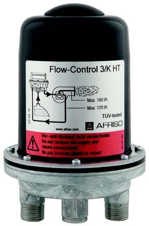
Über diese Betriebsanleitung                                    DE

1   Über diese Betriebsanleitung
    Diese Betriebsanleitung beschreibt den automatischen Heizölentlüfter
    „Flow-Control“ (im folgenden auch „Produkt“). Diese Betriebsanleitung ist Teil
    des Produkts.
    •   Sie dürfen das Produkt erst benutzen, wenn Sie die Betriebsanleitung
        vollständig gelesen und verstanden haben.
    •   Stellen Sie sicher, dass die Betriebsanleitung für alle Arbeiten an und mit
        dem Produkt jederzeit verfügbar ist.
    •   Geben Sie die Betriebsanleitung und alle zum Produkt gehörenden
        Unterlagen an alle Benutzer des Produkts weiter.
    •   Wenn Sie der Meinung sind, dass die Betriebsanleitung Fehler, Wider-
        sprüche oder Unklarheiten enthält, wenden Sie sich vor Benutzung des
        Produkts an den Hersteller.
    Diese Betriebsanleitung ist urheberrechtlich geschützt und darf ausschließ-
    lich im rechtlich zulässigen Rahmen verwendet werden. Änderungen vorbe-
    halten.
    Für Schäden und Folgeschäden, die durch Nichtbeachtung dieser Betriebs-
    anleitung sowie Nichtbeachten der am Einsatzort des Produkts geltenden
    Vorschriften, Bestimmungen und Normen entstehen, übernimmt der Herstel-
    ler keinerlei Haftung oder Gewährleistung.

                                                           Flow-Control           2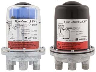
Informationen zur Sicherheit                                DE

2     Informationen zur Sicherheit
2.1   Warnhinweise und Gefahrenklassen
      In dieser Betriebsanleitung finden Sie Warnhinweise, die auf potenzielle
      Gefahren und Risiken aufmerksam machen. Zusätzlich zu den Anweisungen
      in dieser Betriebsanleitung müssen Sie alle am Einsatzort des Produktes
      geltenden Bestimmungen, Normen und Sicherheitsvorschriften beachten.
      Stellen Sie vor Verwendung des Produktes sicher, dass Ihnen alle Bestim-
      mungen, Normen und Sicherheitsvorschriften bekannt sind und dass sie
      befolgt werden.
      Warnhinweise sind in dieser Betriebsanleitung mit Warnsymbolen und Sig-
      nalwörtern gekennzeichnet. Abhängig von der Schwere einer Gefährdungs-
      situation werden Warnhinweise in unterschiedliche Gefahrenklassen unter-
      teilt.

                                   HINWEIS
    HINWEIS macht auf eine möglicherweise gefährliche Situation aufmerksam, die
    bei Nichtbeachtung Sachschäden zur Folge haben kann.

                                                         Flow-Control         3
Informationen zur Sicherheit DE
2.2 Bestimmungsgemäße Verwendung
Dieses Produkt eignet sich ausschließlich für den Einsatz in Einstrangsyste-
men mit Rücklaufzuführung zur kontinuierlichen Entlüftung folgender Flüs-
sigkeiten in Ölfeuerungsanlagen:
• Heizöl EL nach DIN 51603-1
- mit 0 - 20 % Fettsäure-Methylester (FAME) nach EN 14214
• Dieselkraftstoff nach EN 590
- mit 0 - 20 % Fettsäure-Methylester (FAME) nach EN 14214
• Biodiesel, pflanzliche Öle (nur bei Produkt Flow-Control 3/K HT)
Eine andere Verwendung ist nicht bestimmungsgemäß und verursacht
Gefahren.
Stellen Sie vor Verwendung des Produkts sicher, dass das Produkt für die
von Ihnen vorgesehene Verwendung geeignet ist. Berücksichtigen Sie dabei
mindestens folgendes:
• Alle am Einsatzort geltenden Bestimmungen, Normen und Sicherheits-
vorschriften
• Alle für das Produkt spezifizierten Bedingungen und Daten
• Die Bedingungen der von Ihnen vorgesehenen Anwendung
Führen Sie darüber hinaus eine Risikobeurteilung in Bezug auf die konkrete,
von Ihnen vorgesehene Anwendung nach einem anerkannten Verfahren
durch und treffen Sie entsprechende dem Ergebnis alle erforderlichen
Sicherheitsmaßnahmen. Berücksichtigen Sie dabei auch die möglichen Fol-
gen eines Einbaus oder einer Integration des Produkts in ein System oder in
eine Anlage.
Führen Sie bei der Verwendung des Produkts alle Arbeiten ausschließlich
unter den in der Betriebsanleitung und auf dem Typenschild spezifizierten
Bedingungen und innerhalb der spezifizierten technischen Daten und in
Übereinstimmung mit allen am Einsatzort geltenden Bestimmungen, Nor-
men und Sicherheitsvorschriften durch.
Flow-Control 4Informationen zur Sicherheit DE
2.3 Vorhersehbare Fehlanwendung
Das Produkt darf insbesondere in folgenden Fällen und für folgende Zwecke
nicht angewendet werden:
• Einsatz in unverdünnten Additiven, Alkoholen und Säuren
• Einsatz in Druckversorgungsanlagen ohne entsprechende Schutzvorkeh-
rungen
2.4 Qualifikation des Personals
Arbeiten an und mit diesem Produkt dürfen nur von Fachkräften vorgenom-
men werden, die den Inhalt dieser Betriebsanleitung und alle zum Produkt
gehörenden Unterlagen kennen und verstehen.
Die Fachkräfte müssen aufgrund ihrer fachlichen Ausbildung, Kenntnisse
und Erfahrungen in der Lage sein, mögliche Gefährdungen vorherzusehen
und zu erkennen, die durch den Einsatz des Produkts entstehen können.
Den Fachkräften müssen alle geltenden Bestimmungen, Normen und
Sicherheitsvorschriften, die bei Arbeiten an und mit dem Produkt beachtet
werden müssen, bekannt sein.
2.5 Persönliche Schutzausrüstung
Verwenden Sie immer die erforderliche persönliche Schutzausrüstung.
Berücksichtigen Sie bei Arbeiten an und mit dem Produkt auch, dass am Ein-
satzort Gefährdungen auftreten können, die nicht direkt vom Produkt ausge-
hen.
2.6 Veränderungen am Produkt
Führen Sie ausschließlich solche Arbeiten an und mit dem Produkt durch, die
in dieser Betriebsanleitung beschrieben sind. Nehmen Sie keine Verände-
rungen vor, die in dieser Betriebsanleitung nicht beschrieben sind.
Flow-Control 5Transport und Lagerung DE
3 Transport und Lagerung
Das Produkt kann durch unsachgemäßen Transport und Lagerung beschä-
digt werden.
HINWEIS
BESCHÄDIGUNG DES PRODUKTS
• Stellen Sie sicher, dass während des Transports und der Lagerung des Pro-
dukts die spezifizierten Umgebungsbedingungen eingehalten werden.
• Benutzen Sie für den Transport die Originalverpackung.
• Lagern Sie das Produkt nur in trockener, sauberer Umgebung.
• Stellen Sie sicher, dass das Produkt bei Transport und Lagerung stoßge-
schützt ist.
Nichtbeachtung dieser Anweisungen kann zu Sachschäden führen.
Flow-Control 6Produktbeschreibung DE
4 Produktbeschreibung
4.1 Varianten
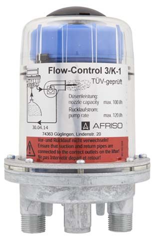
Das Flow-Control 3/K besteht aus
einem Gehäuse aus Zink-Druckguss
mit tankseitigem Anschlussgewinde
G1/4i und brennerseitigen Anschluss-
gewinden G3/8a mit 60°-Konus zum
Anschluss der Brennerschläuche.
Das Produkt verfügt über zwei
getrennte Schwimmerkammern. In
der unteren Schwimmerkammer
befindet sich der Betriebsschwim-
mer, in der oberen der Sicherheits-
schwimmer. Die obere Schwimmer-
kammer verhindert, dass Ölschaum
(beispielsweise bei Inbetriebnahme/
Filterwechsel) durch die Entlüftungs-
bohrung austreten kann und zeigt
Störungen des Entlüftungsventils an.
Das Flow-Control 3/K HT unterschei-
det sich zum Flow-Control 3/K durch
eine nicht transparente Schwimmer-
kammer aus Kunststoff, sowie Dich-
tungen aus FKM. Dadurch ist das
Produkt für höhere Temperaturen
und Pflanzenöl Anwendungen geeig-
net
Abbildung 1: Flow-Control 3/K (oben)
Abbildung 2: Flow-Control 3/K HT (unten)
Flow-Control 7Produktbeschreibung DE
4.2 Anwendungsbeispiel(e)
A. Maximal 4,50 m
A
Abbildung 3: Einbau des Flow-Control 3/K HT oberhalb des Tankspiegels mit selbstsi-
chernder Saugleitung (stetiges Gefälle zum Tank). Die Rückschlagventile in der Ent-
nahmearmatur und am Saugschlauchende müssen dabei entfernt werden.
A C A. Kolben-Antiheberventil
„KAV“
F B. Statischer Vordruck zur
Auslegung des „KAV“
D
G C. Membran-Antiheberventil
B E „MAV“
D. Statischer Vordruck zur
Auslegung des „MAV“
E. Filter
F. Flow-Control
G. Brenner
Abbildung 4: Einbau des Flow-Control 3/K HT unterhalb des Tankspiegels. Um ein
Austreten (Aushebern) von Heizöl bei defekter Saugleitung und höher liegendem
Ölstand im Tank zu verhindern, muss eine Schutzeinrichtung gegen Aushebern (Anti-
heberventil) eingebaut werden.
Flow-Control 8Produktbeschreibung DE
4.3 Funktion
Die Brennerpumpe saugt durch den Filter über das im Produkt einge-
baute Rückschlagventil das Heizöl vom Tank an und fördert es zur Düse.
Die über die Düsenleistung hinausgehende Ölmenge wird von der Pumpe
über die Rücklaufleitung in die Schwimmerkammer gepumpt. Hier erfolgt
unter allmählichem Anstieg des Flüssigkeitspegels die Entlüftung durch
das Entlüftungsventil.
Bei einem Ölniveau von circa 20-30 mm über der Bodenfläche beginnen
die Betriebsschwimmer aufzutreiben und steuern damit das Bypassventil,
welches das entlüftete Rücklauföl der Saugleitung zuführt.
Dadurch wird nur die Ölmenge über den Filter aus dem Tank angesaugt,
die tatsächlich für die Verbrennung benötigt wird. Die Filterstandzeit wird
dadurch stark erhöht. Mit dem langen Filtereinsatz aus Sinterkunststoff
(Optimum) lässt sich die maximal mögliche Standzeit erreichen.
Der zur Pumpe fließende Volumenstrom besteht zum größten Teil aus
entlüftetem Heizöl und in kleineren Teilen aus Öl vom Tank, das noch
Luftanteile enthalten kann.
A. QTank = QDüse
B. QVorlauf
C. QRücklauf
D
A D. QDüse
B
C
Abbildung 5: Beispiel am Flow-Control 3/K HT mit Filter
4.4 Zulassungsdokumente, Bescheinigungen, Erklärungen
Das Produkt ist vom TÜV geprüft (Bericht Nr. S 133 2013 E2).
Flow-Control 9Produktbeschreibung DE
4.5 Technische Daten
Parameter Wert
Allgemeine Daten
Abmessungen (B x H x T) 95 x 147 x 95 mm
Anschluss Brenner G3/8a mit 60°-Konus für Brenner-
schlauch oder G1/4i
Anschluss Tank G1/4i
Düsenleistung Max. 100 l/h
Rücklaufstrom Max. 120 l/h
Abscheideleistung Luft/Gas, abhän- Ca. 4 l/h (nur Entlüftungseinheit)
gig vom Luftgehalt des Brennstoffs Ca. 6 l/h (nach EN 12514-3)
Einbaulage Schwimmergehäuse senkrecht nach
oben
Betriebsüberdruck Max. 0,7 bar (entsprechend stati-
scher Ölsäule von 8 m)
Saugunterdruck Max. 0,5 bar
Prüfdruck 6 bar
Dichtungen
- Typ: 3/K NBR
- Typ: 3/K HT FKM
Temperatureinsatzbereich
Umgebung Max. +60 °C
Betrieb/Medium:
- Typ: 3/K Max. +60 °C
- Typ: 3/K HT Max. +80 °C
Flow-Control 10Montage DE
5 Montage
Das Produkt wird vor dem Brenner installiert. Die Armatur darf über oder
unter dem Tankspiegel eingebaut werden. Die Saugleitung zum Tank kann
bei entsprechenden örtlichen Gegebenheiten (entsprechend dem gültigen,
technischen Regelwerk) als selbstsichernde Saugleitung mit stetigem
Gefälle zum Tank hin verlegt werden. Dabei alle Rückschlagventile vor dem
Produkt entfernen.
5.1 Querschnitt der Saugleitung ermitteln
Bei Umstellung von Zweistranganlagen auf Einstrang-Betrieb sinkt die Strö-
mungsgeschwindigkeit des Öls in der Saugleitung.
Nomogramm zur Bestimmung des Rohrinnendurchmessers (NW) der Hei-
zöl-Saugleitung zur Vermeidung von Gasansammlungen in höher gelegenen
Leitungsbereichen und Gefällstrecken oder Gasbildung bei zu hoher Strö-
mungsgeschwindigkeit.
Stellen Sie sicher, dass der Querschnitt der Saugleitung DIN 4755-2
(Strömungsgeschwindigkeit 0,2 - 0,5 m/s) entspricht, um Luftansammlun-
gen in höher gelegenen Leitungsbereichen und Gefällstrecken zu vermei-
den (Störabschaltungen).
B C A. Düsenverbrauch Brenner
[l/h]
B. Innendurchmesser der
Saugleitung [mm]
E C. Fließgeschwindigkeit des
Heizöls [m/s]
A
D D. < Ø 4 nicht empfehlens-
wert
E. Empfohlener Bereich
nach DIN 4755-2
Abbildung 6: Nomogramm; Beispiel: Fördermenge = 20 l/h, Fließgeschwindigkeit von
circa 0,23 m/s. Es wird eine Leitung mit Rohrdurchmesser 8 x 1 mm (NW 6) benötigt.
Flow-Control 11Montage DE
5.2 Produkt montieren
Stellen Sie sicher, dass die zulässige Umgebungstemperatur von +60 °C
nicht überschritten wird.
Stellen Sie sicher, dass das Produkt nicht auf oder in der Nähe eines
unisolierten Kesselteils, oberhalb zu öffnender Klappen an Feuerungs-
stellen oder am Rauchkanal montiert wird.
Stellen Sie sicher, dass das Schwimmergehäuse senkrecht nach oben
zeigt.
1. Montieren Sie das Produkt mit Hilfe der beigefügten Blechschrauben an
der Kesselblechverkleidung.
2. Verwenden Sie beim Bohren der Bohrlöcher (Ø 3 mm) den Halter als
Schablone.
Stellen Sie sicher, dass für den Anschluss an der Ölpumpe geeignete
Ölschläuche (nach DIN 4798-1) verwendet werden.
Stellen Sie sicher, dass ein Ölfilter
in der Zuleitung vor dem Produkt
montiert ist.
3. Schließen Sie die Brennerschläu-
A che an den beiden Gewindestut-
zen R und V (A) an.
Die Verbindung zum Filter
„Anschluss T“ (B) kann mit dem opti-
B onal beigelegten Schlauch G1/4 (C)
und Überwurfmutter G3/8 (D) herge-
C stellt werden.
D
Flow-Control 12Montage DE
HINWEIS
UNDICHTIGKEIT DES PRODUKTS
Verwenden Sie kein Hanf oder Teflonband zum Eindichten.
• Stellen Sie sicher, das Sie zum Eindichten eine Rohrverschraubung nach
DIN 3852 mit zylindrischem Einschraubgewinde (G-Gewinde) verwenden
und dieses mit einer Flachdichtung oder mit geeignetem Kleber Eindichten.
Nichtbeachtung dieser Anweisungen kann zu Sachschäden führen.
4. Dichten Sie die Verbindungen mit der im Zubehörbeutel enthaltene
Kupfer-Flachdichtung ab. Werden die Brennerschläuche nicht direkt
angeschlossen (beispielsweise Gehäuseausführung mit Vor- und Rück-
lauf-Anschluss G1/4-IG), so können alternativ zylindrische Rohrverschrau-
bungen G1/4 (nach DIN 3852) mit Kupfer-Flachdichtung in das Innenge-
winde G1/4 des Gehäuses eingedichtet werden.
HINWEIS
BESCHÄDIGUNG DES PRODUKTS
• Stellen Sie sicher, dass Sie den Vor- und Rücklaufanschluss nicht vertauscht
anschließen.
Nichtbeachtung dieser Anweisungen kann zu Sachschäden führen.
5.3 Druckprüfung
Bei der Saugleitungs-Druckprüfung den Druckanschluss nicht am Produkt
vornehmen, da das produktseitig integrierte Rückschlagventil die Drucküber-
tragung auf die Saugleitung nicht zulässt.
1. Beziehen Sie das Produkt nicht in die Druckprüfung ein.
Flow-Control 13Montage DE
5.4 Parallelschaltung
Wenn eine Abscheideleistung von mehr als 4l/h Luft/Gas benötigt wird, kön-
nen zwei Produkte parallel angeschlossen werden.
A. Rücklauf
B. Vorlauf
C. Tank
C
A
B
5.5 Entlüftungsschlauch anschließen
Zur Vermeidung von Geruchsbelästigungen durch die abgeschiedene Luft
(beispielsweise beim Einbau in Küchen), kann auf die Haube des Produkts
ein Entlüftungsschlauch angeschlossen werden.
A B A. Schlauchanschluss mit
O-Ring
B. Entlüftungsschlauch
Flow-Control 14Montage DE
1. Entfernen Sie die Abdeckkappe
mit einem Schraubendreher.
2. Montieren Sie den beigelegten
Schlauchanschluss.
3. Schieben Sie den Entlüftungs-
schlauch auf den Schlauchan-
schluss auf und führen ihn ent-
lang der Saugleitung zum Tank
zurück.
4. Fixieren Sie den Entlüftungs-
schlauch mit Kabelbindern.
5. Bringen Sie das andere Ende des
Entlüftungsschlauchs an der Ent-
lüftungsleitung oder am Rücklau-
fanschluss der Entnahmearmatur
des Tanks an, um einen eventuel-
len Leitungsverschluss vorzubeu-
gen.
Der Anschluss an den Rücklaufan-
schluss der Entnahmearmatur kann
mit der beiliegenden Schlauchtülle
vorgenommen werden.
Flow-Control 15Betrieb DE
6 Betrieb
6.1 Ölschaum
Ölschaum kann dann entstehen, wenn die in den Entlüfter mit eingesaugte
Luftmenge größer ist als die mögliche Abscheideleistung des Produkts
(4 l/h). Mögliche Ursachen:
• Leck in der Saugleitung
• Undichte Verschraubungen im Saugbereich
• Erstinbetriebnahme (ohne separate Ansaugpumpe)
• Zu groß dimensionierte Saugleitung (DIN 4755-2 beachten, Strömungs-
geschwindigkeit 0,2-0,5 m/s)
6.2 Ölstand im Schwimmergehäuse
Der Flüssigkeitsstand stellt sich in Abhängigkeit von den anlagebedingten
Betriebsbedingungen ein und liegt im Saugbetrieb bei circa 20-50 mm. Bei
höher liegendem Ölspiegel kann es bei einer dicht verlegten Saugleitung zu
einem vollständig mit Öl gefüllten Schwimmergehäuse kommen. Verursacht
wird dies durch die Absorption der Luft vom Heizöl. Dieser Effekt bewirkt im
Laufe der Zeit einen Abbau des Luftpolsters. Ändern sich die Betriebsbedin-
gungen beispielsweise durch sinkenden Flüssigkeitsstand im Tank, so bildet
sich wieder ein Luftpolster im Schwimmergehäuse.
6.3 Druckbetrieb
Da es im Druckbetrieb mit einer Ölförderpumpe zu keinen Saugausgasun-
gen kommt, ist es nicht sinnvoll hier einen Ölentlüfter einzusetzen.
Im Druckbetrieb sollte ein Einstrangfilter mit Rücklaufzuführung eingesetzt
werden. Sollte es auf Grund des um ∆p (0,5-0,8 bar bei Einstrangfilter mit
Rücklaufzuführung) zusätzlich erhöhten Rücklaufdruckes (=> 0,7 bar Vor-
druck + ∆p des Bypassventil ergibt beispielsweise 1,2-1,5 bar Rücklaufdruck)
zu Problemen mit der Brennerpumpe kommen, so kann ein
„Flow-Control 3/K HT“ verwendet werden.
Stellen Sie sicher, dass Sie für diese Anwendung geeignete Vorkehrun-
gen treffen, die auch im Störfall (defekter Druckminderer) ein Überschrei-
ten des maximal zulässigen Vordrucks von 0,7 bar verhindern (beispiels-
weise über ein Überströmventil, Druckschalter).
Stellen Sie sicher, dass Sie unterhalb der Brennerschläuche und des
Ölentlüfters eine Auffangwanne aufstellen, über welche ein möglicher
Ölaustritt detektiert wird, sowie eine Abschaltung des Brenners erfolgt.
Flow-Control 16Betrieb DE
6.4 Einsatz in hochwassergefährdeten Gebieten
Das Produkt ist geeignet für hochwassergefährdete Gebiete und ist druck-
wasserdicht bis 10 m Wassersäule (1 bar Außendruck).
Stellen Sie sicher, dass sich der Anschluss der Entlüftungsleitung am
Rücklaufanschluss des Tanks befindet oder oberhalb des maximal mögli-
chen Wasserpegels endet.
HINWEIS
FUNKTIONSUNFÄHIGES PRODUKT
• Stellen Sie sicher, dass das Produkt nach einer Überschwemmung ausge-
tauscht wird.
Nichtbeachtung dieser Anweisungen kann zu Sachschäden führen.
6.5 Luftansammlungen
Je nach Art des Filtereinsatzes und des anlagebedingten Saugdruckes kann
die aus dem Öl ausgeschiedene Luft mehr oder weniger vom Filtereinsatz
zurückgehalten werden.
Vor dem "Filter" kann sich, sichtbar in der Filtertasse, ein Luftpolster bilden.
Die Größe des Luftpolsters steht in Abhängigkeit von der Strömungsge-
schwindigkeit und dem Saugdruck im Filter, dass heißt bei großem Durch-
satz können mehr Luftpartikel durch den Filter mitgerissen werden als bei
einer geringen Strömungsgeschwindigkeit (geringer Ölverbrauch am Bren-
ner). Dies bewirkt während den Brennerlaufzeiten, in welchen ein Unterdruck
aufgebaut wird, eine Ölspiegelabsenkung in der Filtertasse außerhalb des
Filters.
Der Innenraum des Filters ist dabei vollständig mit gefiltertem Öl gefüllt, so
dass es nicht zu Betriebsstörungen kommen kann. Die unregelmäßige,
räumlich wirkende Porenstruktur des Siku-Filtereinsatzes bewirkt eine sehr
gute Luftdurchlässigkeit.
Flow-Control 17Außerbetriebnahme und Entsorgung DE
7 Außerbetriebnahme und Entsorgung
Entsorgen Sie das Produkt nach den geltenden Bestimmungen, Normen und
Sicherheitsvorschriften.
1. Demontieren Sie das Produkt (siehe Kapitel "Montage"
in umgekehrter Reihenfolge).
2. Entsorgen Sie das Produkt.
8 Rücksendung
Vor einer Rücksendung Ihres Produkts müssen Sie sich mit uns in Verbin-
dung setzen.
9 Gewährleistung
Informationen zur Gewährleistung finden Sie in unseren Allgemeinen
Geschäftsbedingungen im Internet unter www.afriso.com oder in Ihrem Kauf-
vertrag.
Flow-Control 18Ersatzteile und Zubehör DE
10 Ersatzteile und Zubehör
HINWEIS
BESCHÄDIGUNG DURCH UNGEEIGNETE TEILE
• Verwenden Sie nur Original Ersatz- und Zubehörteile des Herstellers.
Nichtbeachtung dieser Anweisung kann zu Sachschäden führen.
Produkt
Artikelbezeichnung Art.-Nr. Abbildung
Automatischer Heizölent- 69930
lüfter „Flow-Control 3/K“
Automatischer Heizölent- 69978, 69954
lüfter „Flow-Control 3/K“
(G¼)
Automatischer Heizölent- 69929
lüfter „Flow-Control 3/K HT“
Ersatzteile und Zubehör
Artikelbezeichnung Art.-Nr. Abbildung
Kolben-Antiheberventil 20240 -
„KAV“
Membran-Antiheberventil 20139 -
„MAV“
Entlüftungsschlauch, PVC, 20696 -
ø 4 x 1 mm, 20 m Rolle
Flow-Control 19Operating
instructions
Automatic fuel oil de-aerator
Flow-Control
Type: Flow-Control 3/K
Type: Flow-Control 3/K (G1/4)
Type: Flow-Control 3/K HT
Copyright 2015 AFRISO-EURO-INDEX GmbH. All rights reserved.
Lindenstraße 20
74363 Güglingen
BRL A part 1 Telefon+49 7135 102-0
(DIBt)
EN 12514-2 Service+49 7135-102-211
Telefax +49 7135-102-147
info@afriso.com
Version: 03.2016.0 in conjunction with a
PA hose 4 x 1 mm www.afriso.com
ID: 900.000.0048About these operating instructions EN
1 About these operating instructions
These operating instructions describe the automatic fuel oil de-aerator "Flow-
Control" (also referred to as "product" in these operating instructions). These
operating instructions are part of the product.
• You may only use the product if you have fully read and understood these
operating instructions.
• Verify that these operating instructions are always accessible for any type
of work performed on or with the product.
• Pass these operating instructions as well as all other product-related doc-
uments on to all owners of the product.
• If you feel that these operating instructions contain errors, inconsisten-
cies, ambiguities or other issues, contact the manufacturer prior to using
the product.
There operating instructions are protected by copyright and may only be
used as provided for by the corresponding copyright legislation. We reserve
the right to modifications.
The manufacturer shall not be liable in any form whatsoever for direct or con-
sequential damage resulting from failure to observe these operating instruc-
tions or from failure to comply with directives, regulations and standards and
any other statutory requirements applicable at the installation site of the prod-
uct.
Flow-Control 2Information on safety EN
2 Information on safety
2.1 Safety messages and hazard categories
These operating instructions contain safety messages to alert you to poten-
tial hazards and risks. In addition to the instructions provided in these oper-
ating instructions, you must comply with all directives, standards and safety
regulations applicable at the installation site of the product. Verify that you are
familiar with all directives, standards and safety regulations and ensure com-
pliance with them prior to using the product.
Safety messages in these operating instructions are highlighted with warning
symbols and warning words. Depending on the severity of a hazard, the
safety messages are classified according to different hazard categories.
NOTICE
NOTICE indicates a hazardous situation, which, if not avoided, can
result in equipment damage.
Flow-Control 3Information on safety EN
2.2 Intended use
This product may only be used in single-line systems with return pipe con-
nection for continuous de-aeration of the following liquids in oil-fired systems:
• Fuel oil EL as per DIN 51603-1
- with 0 - 20 % fatty acid methyl ester (FAME) as per EN 14214
• Diesel fuel as per EN 590
- with 0 - 20 % fatty acid methyl ester (FAME) as per EN 14214
• Biodiesel, vegetable oils (product Flow-Control 3/K HT only)
Any use other than the application explicitly permitted in these operating
instructions is not permitted and causes hazards.
Verify that the product is suitable for the application planned by you prior to
using the product. In doing so, take into account at least the following:
• All directives, standards and safety regulations applicable at the installa-
tion site of the product
• All conditions and data specified for the product
• The conditions of the planned application
In addition, perform a risk assessment in view of the planned application,
according to an approved risk assessment method, and implement the
appropriate safety measures, based on the results of the risk assessment.
Take into account the consequences of installing or integrating the product
into a system or a plant.
When using the product, perform all work and all other activities in conjunc-
tion with the product in compliance with the conditions specified in the oper-
ating instructions and on the nameplate, as well as with all directives, stand-
ards and safety regulations applicable at the installation site of the product
Flow-Control 4Information on safety EN
2.3 Predictable incorrect application
The product must never be used in the following cases and for the following
purposes:
• Use with undiluted additives, alcohols and acids
• Use in pressure supply systems without appropriate protection precau-
tions
2.4 Qualification of personnel
Only appropriately trained persons who are familiar with and understand the
contents of these operating instructions and all other pertinent product doc-
umentation are authorized to work on and with this product.
These persons must have sufficient technical training, knowledge and expe-
rience and be able to foresee and detect potential hazards that may be
caused by using the product
All persons working on and with the product must be fully familiar with all
directives, standards and safety regulations that must be observed for per-
forming such work.
2.5 Personal protective equipment.
Always wear the required personal protective equipment. When performing
work on and with the product, take into account that hazards may be present
at the installation site which do not directly result from the product itself.
2.6 Modifications to the product
Only perform work on and with the product which is explicitly described in
these operating instructions. Do not make any modifications to the product
which are not described in these operating instructions.
Flow-Control 5Transport and storage EN
3 Transport and storage
The product may be damaged as a result of improper transport or storage.
NOTICE
DAMAGE TO THE PRODUCT
• Verify compliance with the specified ambient conditions during transport or
storage of the product.
• Use the original packaging when transporting the product.
• Store the product in a clean and dry environment.
• Verify that the product is protected against shocks and impact during trans-
port and storage.
Failure to follow these instructions can result in equipment damage.
Flow-Control 6Product description EN
4 Product description
4.1 Versions
Flow-Control 3/K consists of a die-
cast zinc housing with female G1/4
connection thread at the tank side
and male G3/8 connection threads
with 60° cone for connection of the
burner hoses.
The product features two separate
float chambers. The lower float
chamber contains the operating float;
the lower float chamber contains the
safety float. The upper float chamber
keeps oil foam from escaping via the
vent opening (for example, during
commissioning/filter replacement)
and indicates malfunctions of the
vent valve.
Flow-Control 3/K HT differs from
Flow-Control 3/K by a non-transpar-
ent float chamber and FKM seals.
The product is suitable for higher
temperature and vegetable oil appli-
cations.
Fig. 1: Flow-Control 3/K (top)
Fig. 2: Flow-Control 3/K HT (bottom)
Flow-Control 7Product description EN
4.2 Application example(s)
A. Max. 4.50 m
A
Fig. 3: Installation of Flow-Control 3/K HT above the tank level with self-securing suc-
tion line (steady gradient to the tank). The check valves in the withdrawal fitting and at
the end of the suction hose must be removed.
A C A. Piston type anti-siphon
valve "KAV"
F B. Static inlet pressure for
sizing "KAV"
D
G C. Diaphragm type anti-
B E siphon valve "MAV"
D. Static inlet pressure for
sizing "MAV"
E. Filters
F. Flow-Control
G. Burner
Fig. 4: Installation of Flow-Control 3/K HT below the tank level. Protection equipment
against siphoning (anti-siphon valve) must be installed to keep fuel oil from escaping
in the case of a defective suction line and a higher oil level in the tank.
Flow-Control 8Product description EN
4.3 Function
The burner pump draws the fuel oil from the tank via the filter and the
check valve installed in the product and delivers it to the nozzle. The
excess oil (i.e. the oil exceeding the nozzle capacity) is pumped into the
float chamber via the return pipe. While the liquid level gradually
increases in the float chamber, the oil is de-aerated by the de-aeration
valve.
When the oil reaches a level of approximately 20-30 mm above the bot-
tom, the floats begin to operate and actuate the bypass valve, thus deliv-
ering the de-aerated return oil to the suction line.
This way, the system only withdraws the amount of oil from the tank via
the filter which is actually needed for combustion. This considerably pro-
longs the filter service life. The maximum possible service life can be
obtained with the long filter insert made of sintered plastic (Optimum).
The major part of the volume flow to the tank consists of de-aerated fuel
oil and a small portion of fuel oil from the tank which may still contain air.
A. QTank = QNozzle
B. QFlow
C. QReturn
D
A D. QNozzle
B
C
Fig. 5: Example Flow-Control 3/K HT with filter
4.4 Approvals, conformities, certifications
The product is TÜV-tested (report no. S 133 2013 E2).
Flow-Control 9Product description EN
4.5 Technical specifications
Parameter Value
General specifications
Dimensions (W x H x D) 95 x 147 x 95 mm
Burner connection G3/8 male with 60° cone for burner
hose or G1/4 female
Tank connection G1/4 female
Nozzle capacity Max. 100 l/h
Return flow Max. 120 l/h
Separating capacity air/gas, depend- Approx. 4 l/h (de-aeration unit only)
ing on air content of fuel Approx. 6 l/h (as per EN 12514-3)
Mounting position Float housing vertical to the top
Operating overpressure Max. 0.7 bar (corresponds to a static
oil column of approx. 8 m)
Suction vacuum Max. 0.5 bar
Test pressure 6 bar
Seals
- Type: 3/K NBR
- Type: 3/K HT FKM
Operating temperature range
Ambient Max. +60 °C
Operation/medium:
- Type: 3/K Max. +60 °C
- Type: 3/K HT Max. +80 °C
Flow-Control 10Mounting EN
5 Mounting
Install the product upstream of the burner. The fitting may be installed above
or below the tank level. The suction line can be designed as a self-securing
suction line with a steady gradient to the tank if the conditions on site permit
this (according to the applicable technical rules and directives). In this case,
all check valves upstream of the product must be removed.
5.1 Determining the cross section of the suction line
When dual-pipe systems are converted to single-pipe operation, the flow rate
of the oil in the suction line is reduced.
Nomograph for determining the internal pipe diameter (NW) of the fuel oil
suction line in order to keep gas from accumulating in higher pipe sections
and sections with downward gradients, or gas formation resulting from exces-
sively high flow rates.
Verify that the cross section of the suction line according complies with
DIN 4755-2 (flow rate 0.2 to 0.5 m/s) in order to help avoid air cushions in
higher pipe sections and pipes with gradients (shutdowns due to error
conditions).
B C A. Nozzle consumption
burner Brenner [l/h]
B. Inside diameter of the suc-
tion line [mm]
E C. Flow rate of the fuel oil [m/
s]
A
D D. < Ø 4 not advisable
E. Recommended range as
per DIN 4755-2
Fig. 6: Nomograph; Example: Volume = 20 l/h, flow rate = Ø ~ 0.23 m/s. A pipe with
a pipe diameter of 8 x 1 mm (nominal diameter 6) is required.
Flow-Control 11Mounting EN
5.2 Mounting the product
Verify that the ambient temperature of +60 °C is not exceeded.
Verify that the product is not mounted the product on top of or next to a
non-insulated boiler part, above opening dampers at furnaces or to the
flue gas pipe.
Verify that the float housing points vertically to the top.
1. Mount the product to the sheet metal boiler wall using the enclosed tap-
ping screws.
2. Use the bracket as a template when drilling the holes (Ø 3 mm).
Verify that suitable oil hoses as per DIN 4798-1 for connection to the oil
pump are used.
Verify that an oil filter is installed in
the supply line upstream of the
product.
3. Connect the burner hoses to the
A two threaded sockets R and V (A).
The connection to the filter "connec-
tion T" (b) can be made with the
optional, enclosed hose G1/4 (C) and
B a G3/8 (D) union nut.
C
D
Flow-Control 12Mounting EN
NOTICE
LEAKS AT PRODUCT
Do not use hemp or Teflon tape for sealing.
• Verify that you use a screwed pipe connection as per DIN 3852 with cylindri-
cal thread (G thread) and seal it with a flat gasket or with suitable glue.
Failure to follow these instructions can result in equipment damage.
4. Use the copper flat gasket contained in the bag of accessories to seal the
connection. If the burner hoses are not connected directly (for example,
housing version with flow and return connection G1/4 female), you can use
cylindrical pipe connections G1/4 as per DIN 3852 with copper flat gaskets
to make the connection to the G1/4 female thread of the housing.
NOTICE
DAMAGE TO THE PRODUCT
• Verify that you do not interchange the flow and return connections.
Failure to follow these instructions can result in equipment damage.
5.3 Pressure test
When subjecting the suction pipe to a pressure test, the pressure connection
must not be made at the product since the check valve integrated in the prod-
uct does not allow the pressure to be applied to the suction line.
1. Do not include the product in the pressure test.
Flow-Control 13Mounting EN
5.4 Parallel connection
If a separating capacity of more than 4 l/h air/gas is required, two products
can be connected in parallel.
A. Return
B. Flow
C. Tank
C
A
B
5.5 Connecting the vent hose
To avoid odours from the separated air (for example, if the unit is installed in
kitchens), a vent hose can be connected to the Flow-Control hood.
A B A. Hose connection
with O ring
B. Vent hose
Flow-Control 14Mounting EN
1. Remove the cover using a screw-
driver.
2. Mount the enclosed hose connec-
tion.
3. Push the vent hose onto the hose
connection and route it back to the
tank next to the suction line.
4. Fixate the vent hose with cable
ties.
5. Mount the other end of the vent
hose to the de-aeration line or the
return connection of the with-
drawal fitting at the tank to avoid
clogging.
Use the enclosed hose connector for
connection to the return connection
of the withdrawal fitting.
Flow-Control 15Operation EN
6 Operation
6.1 Oil foam
Oil foam may build up if the amount of air sucked into the de-aerator exceeds
the separating capacity of the product (4 l/h). Possible reasons:
• Leak in the suction line
• Screw connections at the suction side not tight
• Initial commissioning (without separate suction pump)
• Suction line rating too great (observe DIN 4755-2, flow rate 0.2-0.5 m/s)
6.2 Oil level in the float housing
The oil level depends on the operating conditions of the facility and amounts
to approximately 20-50 mm in suction mode. If the oil level is higher, the float
housing may be completely filled with oil if the suction line is tight. This is
caused by the absorption of the air through the fuel oil. Over time, this results
in a reduction of the air cushion. When the operating conditions change (for
example, decreasing oil level in the tank), the air cushion is formed again in
the float housing.
6.3 Pressure mode
Since in pressure mode with an oil pump there is no gas formation caused by
suction, it is not meaningful to use an oil vent in this mode.
In pressure mode, it is recommended to use a single-line filter with return
pipe connection. If the return pressure increase by ∆p (0.5-0.8 bar in the case
of single-line filter with return supply) (=> 0.7 bar inlet pressure + ∆p of the
bypass valve results in, for example, 1.2-1.5 bar return pressure) causes
problems with the burner pump, it is possible to use a "Flow-Control 3/K HT".
In the case of such applications, take appropriate measures to keep the
maximum permissible inlet pressure of 0.7 bar from being exceeded even
in the case of error conditions (defective pressure reducer), for example,
by means of a bypass valve, a pressure switch, etc.
A drip pan must be placed below the burner hoses and the oil de-aerator
via which leaking oil is detected and the burner is switched off.
Flow-Control 16Operation EN
6.4 Use in flood hazard areas
The product is suitable for use in flood hazard areas; it is watertight up to 10
m water column (1 bar pressure).
Verify that the vent line is connected to the return connection of the tank
or ends above the maximum possible water level.
NOTICE
INOPERABLE PRODUCT
• Verify that the product is replaced after a flood.
Failure to follow these instructions can result in equipment damage.
6.5 Accumulations of air
Depending on the filter insert and the suction vacuum of the facility, the air
separated from the oil may be retained by the filter insert to a major or minor
degree.
An air cushion may form upstream of the "filter"; this air cushion is visible in
the filter cup. The size of the air cushion depends on the flow rate and the
suction pressure in the filter, i.e. more air particles may be pulled through the
filter at a great throughput compared to a slow flow rate (lower oil consump-
tion by burner). When a vacuum is generated during operation of the burner,
this causes the oil level to decrease in the filter cup outside of the filter.
The inside of the filter is completely filled with filtered oil so that malfunctions
cannot occur. The irregular pore structure of the sintered plastic filter insert
with a spatial effect causes excellent permeability of the air.
Flow-Control 17Decommissioning, disposal EN
7 Decommissioning, disposal
Dispose of the product in compliance with all applicable directives, standards
and safety regulations.
1. Dismount the product (see chapter "Mounting", reverse
sequence of steps).
2. Dispose of the product.
8 Returning the device
Get in touch with us before returning your product.
9 Warranty
See our terms and conditions at www.afriso.com or your purchase contract
for information on warranty.
Flow-Control 18Spare parts and accessories EN
10 Spare parts and accessories
NOTICE
DAMAGE DUE TO UNSUITABLE PARTS
• Only use genuine spare parts and accessories provided by the manufac-
turer.
Failure to follow these instructions can result in equipment damage.
Product
Product designation Part no. Figure
Automatic fuel oil de-aera- 69930
tor "Flow-Control 3/K"
Automatic fuel oil de-aera- 69978, 69954
tor "Flow-Control 3/K" (G¼)
Automatic fuel oil de-aera- 69929
tor "Flow-Control 3/K HT"
Spare parts and accessories
Product designation Part no. Figure
Piston type anti-siphon 20240 -
valve "KAV"
Diaphragm type anti-siphon 20139 -
valve "MAV"
Vent hose, PVC, 20696 -
ø 4 x 1 mm, 20 m reel
Flow-Control 19Notice technique
Purgeur d'air automatique pour fuel
Flow-Control
Type : Flow-Control 3/K
Type : Flow-Control 3/K (G1/4)
Type : Flow-Control 3/K HT
Copyright 2015 AFRISO-EURO-INDEX GmbH. Tous droits réservés.
Lindenstraße 20
74363 Güglingen
BRL A partie 1 Telefon +49 7135-102-0
EN 12514-2
Service +49 7135-102-211
Telefax +49 7135-102-147
info@afriso.com
Version: 03.2016.0 En liaison avec
un tube PA 4 x 1 mm www.afriso.com
ID: 900.000.0048La présente notice technique FR
1 La présente notice technique
Cette notice technique contient la description du purgeur d'air automatique
pour fuel "Flow-Control" (dénommé ci-après "produit"). Cette notice tech-
nique fait partie du produit.
• Utilisez le produit seulement après que vous aurez lu et compris intégra-
lement la notice technique.
• Assurez-vous que la notice technique est disponible en permanence pour
toutes les opérations relatives au produit.
• Transmettez la notice technique et toute la documentation relative au pro-
duit à tous les utilisateurs du produit.
• Si vous êtes d'avis que la notice technique contient des erreurs, des
contradictions ou des ambiguïtés, adressez-vous au fabricant avant d'uti-
liser le produit.
Cette notice technique est protégée au titre de la propriété intellectuelle ; elle
doit être utilisée exclusivement dans le cadre autorisé par la loi. Sous réserve
de modifications.
La responsabilité du fabricant ou la garantie ne pourra être engagée pour des
dommages ou dommages consécutifs résultant d'une inobservation des
directives, règlements et normes en vigueur sur le lieu d'installation du pro-
duit.
Flow-Control 2Informations sur la sécurité FR
2 Informations sur la sécurité
2.1 Consignes de sécurité et classes de risques
Cette notice technique contient des consignes de sécurité destinées à attirer
l'attention sur les dangers et les risques. Outre les instructions contenues
dans cette notice technique, il faut vous assurer de l'observation de tous les
règlements, normes et consignes de sécurité en vigueur sur le lieu d'instal-
lation du produit. Avant d'utiliser le produit assurez-vous que tous les règle-
ments, normes et consignes de sécurité sont connus et respectés.
Dans cette notice technique les consignes de sécurité sont identifiables à
l'aide de symboles de mise en garde et de mots d'avertissement. En fonction
de la gravité du risque les consignes de sécurité sont répartis dans diffé-
rentes classes de risques.
AVIS
AVIS signale une situation potentiellement dangereuse qui, si elle n'est pas évi-
tée, peut entraîner un dommage matériel.
Flow-Control 3Informations sur la sécurité FR
2.2 Utilisation conforme
Le produit est destiné exclusivement à l'utilisation dans les systèmes mono-
tubes avec recyclage pour la purge des liquides suivants dans les chaudières
à fuel :
• Fuel EL selon DIN 51603-1
- contenant 0-20 % d'ester méthylique d'acide gras (EMAG) selon
EN 14214
• Gazole selon EN 590
- contenant 0-20 % d'ester méthylique d'acide gras (EMAG) selon
EN 14214
• Biodiesel (diester), huiles végétales (uniquement avec le produit Flow-
Control 3/K HT)
Toute autre utilisation n'est pas conforme et cause des risques.
Avant d'utiliser le produit, assurez-vous que le produit est adapté à l'usage
que vous prévoyez. À cet effet, tenez compte au moins de ce qui suit :
• Tous les règlements, normes et consignes de sécurité sur le lieu d'instal-
lation
• Toutes les conditions et données spécifiées pour le produit
• Toutes les conditions d'application que vous prévoyez
En outre effectuez une évaluation des risques portant sur l'application
concrète que vous prévoyez à l'aide d'un procédé reconnu et prenez toutes
les mesures de sécurité nécessaires correspondant au résultat. Prenez
aussi en compte les conséquences possibles du montage ou de l'intégration
du produit dans un système ou une installation.
Pendant l'utilisation du produit effectuez toutes les opérations exclusivement
dans les conditions spécifiées dans cette notice technique et sur la plaque
signalétique, conformément aux données techniques spécifiées et en accord
avec tous les règlements, normes et consignes de sécurité en vigueur sur le
lieu d'installation.
Flow-Control 4Informations sur la sécurité FR
2.3 Utilisation non conforme prévisible
Le produit ne doit, en particulier, pas être utilisé dans les cas suivants :
• Utilisation avec des additifs non dilués, alcools et acides
• Utilisation dans les systèmes d'alimentation de pression sans précautions
de protection correspondantes
2.4 Qualification du personnel
Seul le personnel dûment qualifié est autorisé à travailler sur le produit et
avec celui-ci après qu'il aura connu et compris le contenu de cette notice
technique, ainsi que toute la documentation faisant partie du produit.
S'appuyant sur sa formation spécialisée, ses connaissances et ses expé-
riences, le personnel qualifié doit être en mesure de prévoir et reconnaître
les dangers qui peuvent être causés par l'utilisation du produit.
Tous les règlements, normes et consignes de sécurité en vigueur sur le lieu
d'installation doivent être connus du personnel qualifié travaillant sur le pro-
duit et avec celui-ci.
2.5 Équipement de protection individuelle
Utilisez toujours l'équipement de protection individuel requis. En travaillant
sur le produit et avec celui-ci, tenez compte des dangers susceptibles de se
présenter sur le lieu d'installation lesquels n'émanent pas directement du
produit.
2.6 Modification du produit
En travaillant sur le produit et avec celui-ci, effectuez exclusivement les opé-
rations décrites dans cette notice technique. N'effectuez pas de modifica-
tions non décrites dans cette notice technique.
Flow-Control 5Transport et stockage FR
3 Transport et stockage
Un transport et un stockage inadéquats risquent de causer des dommages
au produit.
AVIS
DOMMAGE DU PRODUIT
• Assurez-vous que les conditions ambiantes spécifiées sont respectées pen-
dant le transport et le stockage.
• Utilisez l'emballage d'origine pour le transport.
• Stockez le produit dans un lieu sec et propre.
• Assurez-vous que le produit est à l'abri des chocs pendant le transport et le
stockage.
La non-observation de ces instructions peut causer des dommages maté-
riels.
Flow-Control 6Description du produit FR
4 Description du produit
4.1 Variantes
Flow-Control 3/K consiste en un boî-
tier en zinc (moulage sous pression)
avec raccordement fileté femelle G1/4
(réservoir) et raccordements filetés
mâles G3/8 avec cône 60° (tuyaux de
brûleur).
Le produit dispose de deux
chambres de flotteur. La chambre
inférieure contient le flotteur de ser-
vice, la chambre supérieure le flot-
teur de sécurité. La chambre supé-
rieure empêche l'écoulement du
mousse de fuel par l'orifice de purge
(par exemple pendant la mise en ser-
vice / le changement de filtre) et
indique un éventuel dysfonctionne-
ment de la soupape de purge.
La différence entre Flow-Control 3/K
HT et Flow-Control 3/K est une
chambre de flotteur non-transparente
et des joints en matière FKM. Le pro-
duit est donc adapté à des tempéra-
tures plus élevées et des applications
avec des huiles végétales.
Figure 1: Flow-Control 3/K (en haut)
Figure 2: Flow-Control 3/K HT (en bas)
Flow-Control 7Description du produit FR
4.2 Exemple(s) d'application
A. Maxi 4,50 m
A
Figure 3: Installation du Flow-Control 3/K HT au-dessus du niveau du réservoir avec
conduite d'aspiration en sécurité intrinsèque (en pente régulière vers le réservoir).
Dans ce cas, il faut retirer les clapets anti-retour dans l'unité de prélèvement et à
l'extrémité du tuyau d'aspiration.
A C A. Valve anti-siphon à piston
"KAV"
F B. Pression d'entrée statique
pour le dimensionnement
D du "KAV"
G
B E C. Valve anti-siphon à
membrane "MAV"
D. Pression d'entrée statique
pour le dimensionnement
du "MAV"
E. Filtre
F. Flow-Control
G. Brûleur
Figure 4: Installation de Flow-Control 3/K HT en dessous du niveau du réservoir. Pour
éviter un écoulement éventuel de fuel en cas de conduite d'aspiration défectueuse ou
de niveau supérieur dans le réservoir il faut installer un dispositif de protection contre
l'effet siphon (valve anti-siphon).
Flow-Control 8Description du produit FR
4.3 Fonctionnement
La pompe du brûleur aspire le fuel à travers le filtre et le clapet anti-retour
intégré dans le produit pour alimenter le gicleur. Le volume de fuel aspiré,
supérieur au débit du gicleur, est refoulé par la pompe du brûleur dans la
chambre de flotteur. Le niveau monte progressivement et le fuel est purgé
au travers de la soupape de purge.
Avec un niveau de fuel d'environ 20-30 mm les flotteurs de service com-
mence à monter et pilotent la vanne de bypass (dérivation) ce qui permet
au fuel purgé d'être recyclé à la conduite d'aspiration.
Ce qui fait que seule la quantité de fuel utile au brûleur est aspirée dans
le réservoir au travers du filtre. Ceci prolonge considérablement la durée
de vie du filtre. L'élément filtrant long en matière plastique Siku permet
d'atteindre la durée de vie maximale.
Le débit volumique vers la pompe est ainsi principalement constitué de
fuel purgé et secondairement de fuel en provenance du réservoir qui peut
encore contenir de l'air.
A. QRéservoir = QGicleur
B. QAller
C. QRetour
D
A D. QDicleur
B
C
Figure 5: Exemple Flow-Control 3/K HT avec filtre
4.4 Agréments, certificats, déclarations
Le produit est testé par le TÜV (rapport no° S 133 2013 E2).
Flow-Control 9Description du produit FR
4.5 Caractéristiques techniques
Paramètre Valeur
Caractéristiques générales
Dimensions (L x H x P) 95 x 147 x 95 mm
Raccordement brûleur G3/8 mâle avec cône 60° pour tuyau
du brûleur ou G1/4 femelle
Raccordement réservoir G1/4 femelle
Débit du gicleur Max. 100 l/h
Débit volumique retourné Max. 120 l/h
Puissance de séparation d'air/gaz Env. 4 l/h (purgeur seul)
dépend de la teneur en air du fuel Env. 6 l/h (selon EN 12514-3)
Position d'installation Vertical, chambre de flotteur vers le
haut
Pression de service Max. 0,7 bar (correspond à 8 m de
hauteur de colonne de fuel)
Dépression d'aspiration 0,5 bar max.
Pression d'essai 6 bar
Joints
- Type : 3/K NBR
- Type : 3/K HT FKM
Plage de température
Ambiante Max. +60 °C
Service/fluide :
- Type : 3/K Max. +60 °C
- Type : 3/K HT Max. +80 °C
Flow-Control 10Montage FR
5 Montage
Le produit est à installer en amont du brûleur. L'unité peut être montée au-
dessus ou en dessous du niveau du réservoir. La conduite d'aspiration peut
être posée comme conduite d'aspiration à sécurité intrinsèque (conformé-
ment aux règles techniques). Dans ce cas, il faut retirer tous les clapets anti-
retour en amont du produit.
5.1 Déterminer la section de la conduite d'aspiration
En cas de conversion d'un système à deux conduites en un système à
conduite unique, il y a ralentissement de l'écoulement du fuel dans la
conduite d'aspiration.
Nomogramme pour la détermination du diamètre intérieure de la conduite
d'aspiration pour éviter l'accumulation de gaz dans les tronçons de la
conduite et les segments en déclivité se trouvant dans les parties supé-
rieures et en cas des vitesses d'écoulement trop élevées.
Assurez-vous que la section de conduite d'aspiration conforme à
DIN 4755-2 (vitesse d'écoulement de 0,2 à 0,5 m/s) pour éviter l'accumu-
lation d'air dans les tronçons de la conduite et les segments en déclivité
se trouvant dans les parties supérieures (coupures par défaillance).
B C A. Consommation du gicleur
du brûleur [l/h]
B. Diamètre intérieur de la
conduite d'aspiration [mm]
E C. Vitesse d'écoulement du
fuel [m/s]
A
D D. < Ø 4 non recommandé
E. Plage recommandée
selon DIN 4755-2
Figure 6: Nomogramme, exemple : Refoulement = 20 l/h, vitesse d'écoulement
env.0,23 m/s. Il faut prévoir une conduite de 8 x 1 mm diamètre intérieur (DI 6).
Flow-Control 11Montage FR
5.2 Montage du produit
Assurez-vous que la température ambiante autorisée de +60 °C n'est pas
dépassé.
Évitez tout montage du produit sur une partie non isolée de la chaudière
ou à proximité d'une telle partie, au-dessus de clapets à ouvrir aux
endroits de combustion ou au tuyau de tirage.
Vérifiez que la chambre du flotteur est en position verticale et dirigé vers
le haut.
1. Fixez le produit à l'enveloppe en tôle de la chaudière à l'aide des quatre
vis à tôle.
2. Pour visser les vis (Ø 3 mm), servez-vous du support comme gabarit.
Utilisez des tuyaux de fuel appropriés pour le branchement la pompe à
huile (selon DIN 4798-1).
Installez un filtre à huile dans la
conduite d'alimentation en aval du
produit.
3. Branchez les tuyaux de brûleur
A aux raccords filetés R et V (A).
Le branchement au filtre, "raccord T"
(B), peut être effectué avec le tuyau
en option G1/4 (C) et un écrou-rac-
B cord G3/8 (D).
C
D
Flow-Control 12Sie können auch lesen