User Manual ALICE Calibration Pulser System 2020 - Read The Docs
←
→
Transkription von Seiteninhalten
Wenn Ihr Browser die Seite nicht korrekt rendert, bitte, lesen Sie den Inhalt der Seite unten
ALICE Calibration Pulser System 2020

                        User Manual

© IKF ELEKTRONIK 07-07-2020 V1.0.0
                                               1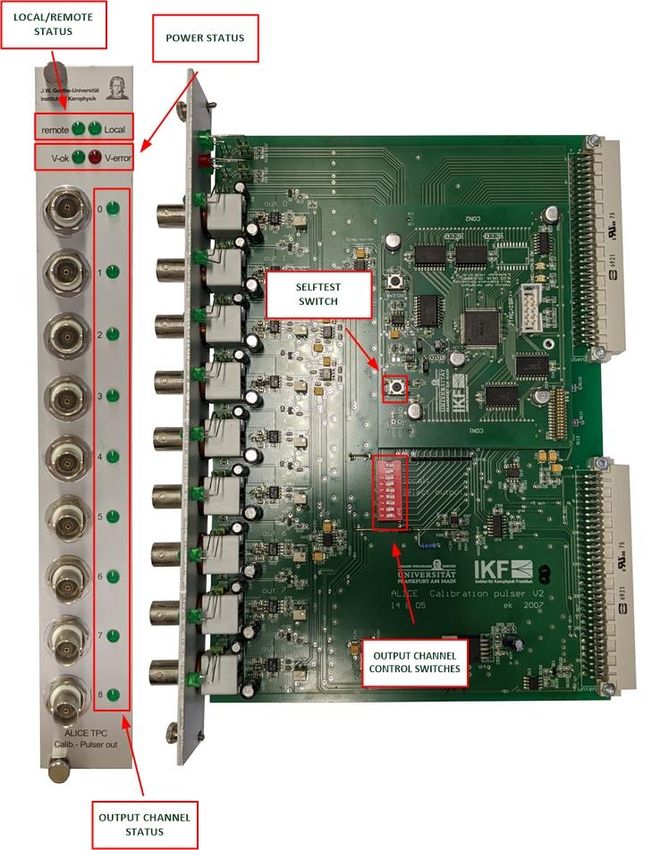
Inhalt (Content)
The “Calibration Pulser”- System overview ......................................................................................... 5
1. The ALICE Calibration Pulser 2020 Card........................................................................................... 6
   Overview: .................................................................................................................................................. 7
FRONTPANEL INDICATORS .................................................................................................................. 8
   Busy indicator ............................................................................................................................................ 8
   Clock INTERNAL/EXTERNAL indicator........................................................................................................ 9
FRONTPANEL PUSH BUTTON & PLUGS .............................................................................................. 10
   EXT. CLOCK & TRIGGER input via 4-pol. LEMO plug ................................................................................ 10
   EXT. CLOCK & TRIGGER input via Fiber Optic Connector ........................................................................ 11
   Monitor output LEMO plug ..................................................................................................................... 11
   ETHERNET RJ-45 input plug (XPORT) ....................................................................................................... 12
   USB input plug ......................................................................................................................................... 12
   Reset push-button ................................................................................................................................... 12
PCB SWITCHES (on PCB only) ............................................................................................................ 12
   PRG. - Switches ........................................................................................................................................ 12
2. ALICE Calibration Pulser 2020 Card Setup ...................................................................................... 13
   ETHERNET ................................................................................................................................................ 13
   USB .......................................................................................................................................................... 13
3. Control the ALICE Calibration Pulser 2020 Card & Power Amplifier Card(s) ..................................... 14
Ethernet Redirection and USB to RS232 Setup ................................................................................... 15
4. The ALICE Calibration Pulser 2020 Waveform Generator V1.0: ....................................................... 15
   Overview: ................................................................................................................................................ 15
Program description ......................................................................................................................... 16
5. The Power Amplifier Card ............................................................................................................. 17
   Overview: ................................................................................................................................................ 18
FRONTPANEL INDICATORS ................................................................................................................ 19
   Power status (current) indicators............................................................................................................ 19
   Mode Status indicators ........................................................................................................................... 19
   Channel indicators ................................................................................................................................... 20

© IKF ELEKTRONIK 07-07-2020 V1.0.0
                                                                                                                                                                  2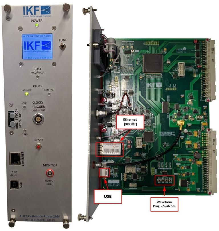
FRONTPANEL PLUGS ......................................................................................................................... 20
   BNC plugs................................................................................................................................................. 20
PCB PUSH BUTTON & SWITCHES ....................................................................................................... 21
   Local control with the 9-pin DIP- switch ................................................................................................. 21
   Selftest push-button:............................................................................................................................... 21
6. The Binary Mode Control .............................................................................................................. 22
   Frame construction (Request/Response):............................................................................................... 22
ALICE Calibration Pulser 2020 Commands: ........................................................................................ 22
   Internal Clock ON/OFF............................................................................................................................. 22
   Clock source INTERNAL/EXTERNAL ......................................................................................................... 22
   Clock source INTERNAL/EXTERNAL ......................................................................................................... 23
   Set Waveform Program No ..................................................................................................................... 23
   Readout Voltage Monitor........................................................................................................................ 23
   Voltage Monitor Reset ............................................................................................................................ 24
   This command resets the voltage monitor of the “ALICE Calibration Pulser 2020”- card. ..................... 24
   Program Waveform Data ........................................................................................................................ 25
   Readout Waveform Data......................................................................................................................... 25
   Firmware Info .......................................................................................................................................... 27
   Trigger source INTERNAL/EXTERNAL....................................................................................................... 27
   Load defaults ........................................................................................................................................... 28
   Save defaults ........................................................................................................................................... 28
ALICE Power Amplifier Commands: ................................................................................................... 29
   Power Amplifier Card - Online Status...................................................................................................... 29
   Power Amplifier Card – Read Output Channels Status ........................................................................... 29
   Power Amplifier Card - OPEN/CLOSE Output Channel(s) ........................................................................ 30
   Power Amplifier Card – Read Power Monitor ......................................................................................... 31
   Power Amplifier Card - Power Monitor Reset ......................................................................................... 32
   Power Amplifier Card - Global Reset ....................................................................................................... 32
Error Codes: ..................................................................................................................................... 33
   Error Code 0 – COMMAND ERROR .......................................................................................................... 33

© IKF ELEKTRONIK 07-07-2020 V1.0.0
                                                                                                                                                              3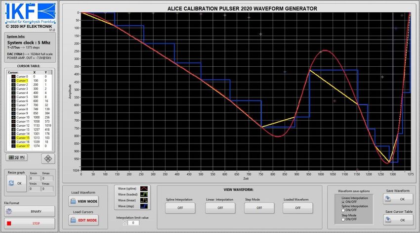
Error Code 1 – LENGTH ERROR................................................................................................................ 33
  Error Code 2 – TIMEOUT ERROR ............................................................................................................. 33
  Error Code 3 – PARAMETER ERROR ........................................................................................................ 33

© IKF ELEKTRONIK 07-07-2020 V1.0.0
                                                                                                                                              4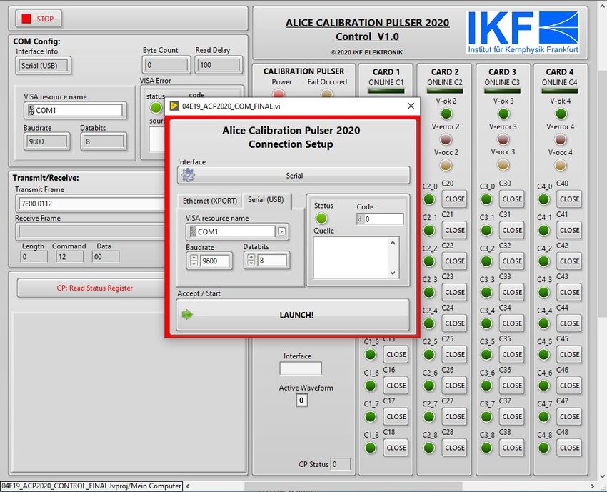
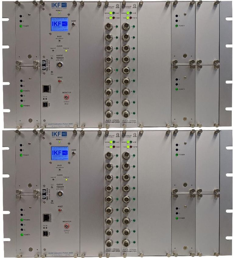
The “Calibration Pulser”- System overview

Das „ALICE – Kalibrierpulser“- System besteht aus zwei Eurorahmen doppelter Höhe mit je einer „ALICE-
Kalibrierpulser 2020“- Karte, einem Einfachnetzteil (5V/4A), einem Zweifachnetzteil (+-5.7V/1.4A) und
zwei Einfachnetzteil (-16.5V/1.5A). Beide Eurorahmen sind mit je zwei ALICE Power Amplifier - Karten
bestückt.

The „Alice- Calibration Pulser 2020“- system contains two assembly groups. Each assembly group
contains one “Alice-Calibration Pulser 2020”- card, one dual power supply (+-5.7V/1.4A), a single power
supply (+5V/4A) and two single Power supplys (-16.5V/1.5A). Furthermore, both systems contains two
“Power Amplifier”- cards.

Optional sind zwei Power-Amplifier und zwei Einfachnetzteil- Steckplätze für Erweiterungen vorhanden.
Da die Steuersoftware universell ausgelegt wurde, werden diese dort berücksichtigt.

Optionally, two power amplifiers and two single power supply slots are available for extensions. Since the
control software has been designed universally, it is taken into account there.

© IKF ELEKTRONIK 07-07-2020 V1.0.0
                                                                                                          5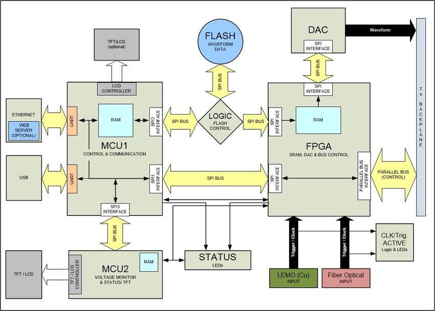
1. The ALICE Calibration Pulser 2020 Card

© IKF ELEKTRONIK 07-07-2020 V1.0.0
                                            6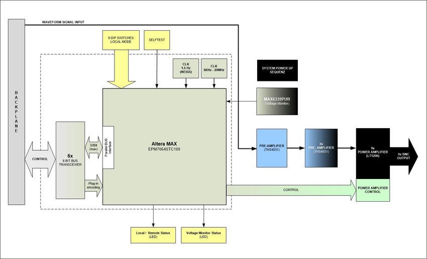
Overview:

© IKF ELEKTRONIK 07-07-2020 V1.0.0
                                     7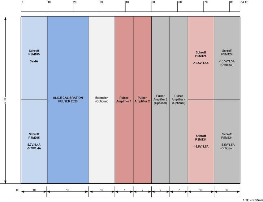
FRONTPANEL INDICATORS

LCD TFT Display

Das LCD TFT Display zeigt die genauen Spannungswerte der „ALICE –Kalibrierpulser 2020“- Karte an. Des
weiteren Informationen zum aktuellen Betriebszustand und zur Firmware. Diese Informationen können
über den Taster „FUNC“ eingeblendet werden.

The LCD display shows the exact voltage values of the "ALICE Calibration Pulse 2020" card. Furthermore,
it shows information’s of the current operating status or firmware. This information’s can displayed by
using the "FUNC" button.

Power indicator

Die Power LED zeigt den aktuellen Versorgungsspannungszustand der „ALICE –Kalibrierpulser 2020“-
Karte an.

  LED zeigt GRÜN            Aktuelle Versorgungsspannungen sind in Ordnung
  LED zeigt ROT             Aktueller Versorgungsspannungsabfall/-fälle
  LED blinkt ROT/GRÜN       Aktuelle Spannungen in Ordnung. Versorgungsspannungsfehler wurde in
                            der Vergangenheit festgestellt und gespeichert.

The Power- LED indicates the actual power-supply status of the “ALICE- Calibration Pulser 2020“- card.

  LED illuminates GREEN          Current supply voltages ok
  LED illuminates RED            Current supply voltage(s) fail.
  LED alternates RED/GREEN       Current voltages are ok, but a voltage fail in the past was detected.

Busy indicator
Diese LED zeigt „orange“ wenn der Mikrocontroller oder der FPGA beschäftigt ist.

This LED illuminates orange, if the Microcontroller or FPGA is busy.

© IKF ELEKTRONIK 07-07-2020 V1.0.0
                                                                                                          8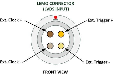
Clock INTERNAL/EXTERNAL indicator
Diese LED’s zeigen den aktuellen gewählten FPGA-Taktquellen Modus an.

  LED „External“ zeigt GRÜN      Externer Takteingang über die „Ext.-CLOCK“ Buchse (Lemo 4pol. oder
                                 Fiber Optical) gewählt.

  LED „Internal“ zeigt GRÜN      Interner 10 MHz Oszillator als FPGA Takt gewählt.

This LED’s indicates the actual FPGA- Clock source mode.

  LED “External” indicates GREEN         External clock source via the “Ext.-CLOCK” plug (Lemo 4-pin or
                                         Fiber Optical Input) is used.

  LED “Internal” indicates GREEN         Internal 10 MHz oscillator is used as FPGA Clock.

Ext. Clock and Ext. Trigger Indicators

Diese LED’s blinken wenn ein aktives externes Taktsignal und/oder ein externer Trigger über die „ Fiber
Optical“ Stecker oder den 4-pol. LEMO Stecker erkannt wird.

These LEDs flash when there is an active external clock signal and / or an external trigger via the "Fiber
Optical" connector or the 4-pin. LEMO connector is detected.

© IKF ELEKTRONIK 07-07-2020 V1.0.0
                                                                                                             9
FRONTPANEL PUSH BUTTON & PLUGS
EXT. CLOCK & TRIGGER input via 4-pol. LEMO plug
Für die Verwendung des 4-pol. LEMO Eingang Buchse als Externe Signalquelle muss der LVDS (Cu) Input-
Mode aktiviert werden.
Wird der „External clock“- Mode benutzt, muss an diesen Eingängen das Taktsignal (5MHz; LVDS)
zugeführt werden.
Wird der „External Trigger“ – Mode benutzt, muss dieser ebenfalls an diesen Eingängen (LVDS) zugeführt
werden.
Der Externe Trigger muss High-Aktiv sein. Dieser muss mindestens 5us und maximal 200us high bleiben.
For using the 4-pin. LEMO input connector as external signal source, the LVDS (Cu) input mode must be
activated.
In „External clock“- mode, this input plug is used to feed a clock (5MHz; LVDS).
If the "External Trigger" mode is used, this must also be applied to these inputs (LVDS).
The external trigger must be high active. The trigger must remain high at least 5us and maximum 200us.
LEMO No.: EGG.1B.304.CLL
© IKF ELEKTRONIK 07-07-2020 V1.0.0
10EXT. CLOCK & TRIGGER input via Fiber Optic Connector
Für die Verwendung der „Fiber Optical Receivers“ muss der Optical Input-Mode aktiviert werden.
Wird der „External clock“- Mode benutzt, muss an diesen Eingängen ein Taktsignal (5MHz; Lichtleiter)
zugeführt werden.
Wird der „External Trigger“ – Mode benutzt, muss dieser ebenfalls an diesen Eingängen (Lichtleiter)
zugeführt werden.
Der Externe Trigger muss High-Aktiv sein. Dieser muss mindestens 5us und maximal 200us high bleiben.
To use the "Fiber Optical Connectors", the optical input mode must be activated.
In „External clock“– mode, this input plug is used to feed a 5MHz (Optical Link) clock.
If the "External Trigger" mode is used, this must also be applied to these inputs (Optical Link).
The external trigger must be high active. The trigger must remain high at least 5us and maximum 200us.
125 Megabaud Versatile Fiber Optic Connectors (AVAGO HFBR-2526Z Receivers)
Monitor output LEMO plug
An der „MONITOR“ Ausgangsbuchse wird ein Prüfsignal, ähnlich dem „ALICE-Kalibrierpulser 2020“-
Ausgangssignal zur Überprüfung ausgegeben. Dieses Signal muss mit 50Ω abgeschlossen werden.
For diagnosis, the “MONITOR”- output plug gives out a test signal similar to the “ALICE- Calibrationpulser
2020”- output signal. This signal must be terminated with 50Ω.
© IKF ELEKTRONIK 07-07-2020 V1.0.0
11ETHERNET RJ-45 input plug (XPORT)
Mittels dieser RJ-45 Buchse wird zur Steuerung des „ALICE Kalibrierpulser 2020 “-Systems eine Ethernet-
Schnittstelle bereitgestellt. Für die Verwendung der der Ethernet- Schnittstelle muss diese im Interface-
Mode aktiviert werden.
The RJ-45 Plug provides an Ethernet interface to control the “ALICE-Calibration Pulser 2020”- system. To
use the Ethernet interface, it must be activated in interface mode.
USB input plug
Alternativ zur Ethernet Schnittstelle wird ein USB Anschluss zur Systemsteuerung angeboten. Für die
Verwendung der der USB- Schnittstelle muss diese im Interface- Mode aktiviert werden.
Alternatively, to the Ethernet interface, a USB plug exists. This plug interfaces the system via USB. To use
the USB interface, it must be activated in interface mode.
Reset push-button
Durch das betätigen des „RESET“- Tasters auf der Frontplatte, wird ein komplettes Rücksetzen (inklusive
des Ethernet- Adapters) der „ALICE-Kalibrierpulser 2020“- Karte erreicht.
A reset (including the Ethernet interface) of the “ALICE-Calibration Pulser 2020”- card will be performed,
by pressing the “RESET” button.
PCB SWITCHES (on PCB only)
PRG. - Switches
Über die auf dem PCB der „Kalibrierpulser“- Karte vorhanden Miniatur-Taster, kann man lokal die vier
Kurvenform Programme anwählen.
These switches can be used to change the four Waveform programs.
© IKF ELEKTRONIK 07-07-2020 V1.0.0
122. ALICE Calibration Pulser 2020 Card Setup
ETHERNET
Die Ethernet Schnittstelle ist als „XPORT03“ der Firma Lantronix ausgeführt. Es handelt sich eigentlich um
einen UART zu Ethernet Konverter.
The “Calibration Pulser” Ethernet port is implemented as a UART to Ethernet converter named
“XPORT03” from Lantronix.
Die einfachste Möglichkeit mit dem „Kalibrierpulser“-System via Ethernet zu kommunizieren, ist die von
Lantronix breitgestellte „COM Port Redirection“- Software unter Windows 7/10 zu verwenden. Des
Weiteren besteht die Möglichkeit direkt über TCP/IP oder UDP mit dem System zu kommunizieren.
The simplest way to control the “Calibration Pulser”- system via Ethernet, is to install under Windows
7/10 the com-port redirection software from Lantronix. It is also possible to reach the system direct over
TCP/IP or UDP protocol.
Für die Inbetriebnahme und Konfiguration des Ethernet Adapters (XPORT) benutzen sie bitte den
Lantronix XPORT USER Guide!
To configure the Ethernet port please use the “Lantronix” XPORT user guide to install.
USB
Die zweite Möglichkeit mit dem „Kalibrierpulser“- System zu kommunizieren ist es, die vorhandene USB
Schnittstelle zu benutzen. Es handelt sich um einen RS232 zu USB Konverter. In Windows 7/10 Systemen
wird er als virtueller COM-Port erkannt.
A second way to control the “Calibration Pulser”- system is to use the implemented USB interface. It is a
UART to USB converter. In Windows 7/10 systems, it is recognized as a virtual COM port.
© IKF ELEKTRONIK 07-07-2020 V1.0.0
133. Control the ALICE Calibration Pulser 2020 Card & Power Amplifier Card(s)
Zum Steuern des Kalibrierpulsers steht eine Testsoftware basierend auf LabVIEW zur Verfügung. Mit
dieser können alle Funktionen des Kalibrierpulser- Systems angesprochen werden. Die Kommunikation
kann entweder über Ethernet (TCP) oder über USB (USB to Serial) erfolgen.
A Test software based on LabVIEW is available to control the calibration pulse. All functions of the
“Calibration- Pulser- System” can be addressed with this.
Communication can take place either via Ethernet (TCP) or via USB (USB to Serial).
© IKF ELEKTRONIK 07-07-2020 V1.0.0
14Ethernet Redirection and USB to RS232 Setup
Setup USB to Serial:
Standard (not changeable): Baud: 9600 Data: 8 Stop: 1 Parity: None
Setup Ethernet:
Standard: Port 10001
Die Ethernet Konfiguration der „Alice Kalbrierpulser 2020 - Karte“ kann via Web Interface auf der
Ethernet Schnittstelle (XPORT) angepasst werden.
The Ethernet configuration of the "Alice Kalbrierpulser 2020 - Card" can be changed via the web interface
on the Ethernet interface (XPORT).
4. The ALICE Calibration Pulser 2020 Waveform Generator V1.0:
Overview:
© IKF ELEKTRONIK 07-07-2020 V1.0.0
15Program description
Das „Waveform Generator“- Programm wird verwendet, um für die „ALICE- Kalibrierpulser 2020“-
Karte(n) die benötigten „Kurvenformdaten“- Datei zu erstellen.
The „Waveform Generator“- program is used to calculate the needed waveform data file for the “ALICE-
Calibration Pulser 2020”- card.
Der „Kalibrierpulser“ erwartet als Kurvenform- Datenformat eine Binärdatei aus 1375 fortlaufenden
hexadezimalen 16bit Datenworten mit einer Bit-Weite zwischen 0 und 1023 (10bit).
The „Calibration Pulser” needs a binary file, filled with 1375 hexadecimal 16bit words with a wide
between 0 and 1023 (10 bit).
Im „Waveform Generator“- Programm existieren drei verschiede Kurvenform- Modi. Eine „Spline“-
Interpolation, eine „Lineare“- Interpolation und ein „Step“- Modus. Des Weiteren bietet das Programm
zwei verschieden Möglichkeiten erstellte Kurvenformen wieder einzulesen. Die erste Möglichkeit ist der
sogenannte „View Mode“, mittels der man die „Waveform“- Dateien (*.bin) wieder einlesen kann. Die
zweite Möglichkeit ist der „Edit- Mode“ mittels diesem die zuvor erstellten Cursordatei (*.csr) wieder
einlesen und bearbeiteten kann.
The „Waveform Generator“- program has three different modes. A “Spline”- interpolation, a “Linear”-
interpolation and a “Step”- mode. Furthermore, two different options exist to read in waveforms. A “View
Mode” who reads in a Waveform data file (*.bin ) and a “Edit Mode” who can read Cursor-Table file
(*.csr) for edit.
Die Kurvenform kann auf zwei verschieden Arten manipuliert werden. Einmal im „Waveform“- Graphen
mit der Hilfe von Fadenkreuze, oder mittels der Verwendung der „Cursor“- Tabelle.
The Waveform can be manipulated in two different ways. The first method is to use the cross hairs
directly in the “Waveform”- graph. The second method is to use the cursor table.
© IKF ELEKTRONIK 07-07-2020 V1.0.0
165. The Power Amplifier Card
© IKF ELEKTRONIK 07-07-2020 V1.0.0
17Overview:
© IKF ELEKTRONIK 07-07-2020 V1.0.0
18FRONTPANEL INDICATORS
Power status (current) indicators
Die Power Status LED‘s zeigt den aktuellen Versorgungsspannungszustand der „Power Amplifier“- Karte
an.
V-ok LED leuchtet GRÜN Aktuelle Versorgungsspannungen in Ordnung
V-error LED leuchtet ROT Aktueller Versorgungsspannungsabfall
The Power- LED indicates the actual power-supply status of the „Power Amplifier “- card.
V-ok LED illuminates GREEN Current supply voltage(s) ok
V-error LED illuminates RED Current supply voltage(s) fail.
Mode Status indicators
Die Mode LED’s zeigen den Zustand (local oder remote) in der sich die „Power Amplifier“- Karte befindet
an. In „Remote“- Betrieb wird die Karte über den „Kalibrierpulser“ via Ethernet oder RS232 über den
„Backplane“- Bus gesteuert. Im lokalen Betrieb werden die Verstärkerausgänge über den Dip- Schalter
auf dem PCB eingestellt.
remote LED leuchtet GRÜN Karte ist in REMOTE Betrieb.
local LED leuchtet GRÜN Karte ist in LOCAL Betrieb.
These LED’s shows the mode status (local or remote) of the „Power Amplifier“-card. If the remote LED
illuminate, the card can controlled by the “Calibration Pulser” via Ethernet or USB. Is the “Power
Amplifier”- card in local mode, the amplifier outputs can be controlled by the 9 pin DIP- switch on the
PCB.
remote LED illuminates GREEN Card is in remote mode.
local LED illuminates GREEN Card is in local mode.
© IKF ELEKTRONIK 07-07-2020 V1.0.0
19Channel indicators
Diese LED’s zeigen an ob der dazugehörige Verstärkerausgang aktiv oder inaktiv ist. Leuchtet diese LED
grün, ist der dazugehörige Ausgang aktiv. Leuchtet diese LED nicht, ist dieser inaktiv.
These LED’s shows the status of the associated amplifier output. If this LED illuminates green the output is
active. If this LED off, the associated output is inactive.
FRONTPANEL PLUGS
BNC plugs
Die Frontplatte der „Power Amplifier“- Karte stellt neun BNC Buchsen bereit. An diesen Buchsen werden
die verstärkten Kurvenform-Signale (ca. -7V@50Ω) ausgegeben.
The front panel of the „Power Amplifier“- card provides nine BNC-plugs. These plugs are used to put out
the amplified waveform signals (-7V@50Ω).
© IKF ELEKTRONIK 07-07-2020 V1.0.0
20PCB PUSH BUTTON & SWITCHES
Local control with the 9-pin DIP- switch
Ist die „ALICE- Kalibrierpulser“- Karte im System nicht vorhanden bzw. gezogen, gehen alle eingesteckten
„Power Amplifier“- Karten in einen lokalen Betriebsmodus. Durch einen auf dem PCB vorhandenen 9 pol.
DIP- Schalter hat man weiterhin die Möglichkeit die Verstärker- Ausgangskanäle an oder abzuschalten.
If the “ALICE-Calibration Pulser”- card is not plugged in, all installed “Power Amplifier”- cards switch to
local Mode. In this mode, it is possible to control the amplifier outputs via a 9-pin DIP switch on the PCB.
“ON” schaltet den jeweiligen Kanal(1-9) durch.
“ON” opens the corresponding channel(s) (1-9).
Selftest push-button:
Durch das betätigen dieses Tasters, wird eine Test-Sequenz an den Verstärkerausgängen durchgeführt.
After this pushbutton is pressed, a Selftest sequence is carried out at the amplifier output channels.
.
© IKF ELEKTRONIK 07-07-2020 V1.0.0
216. The Binary Mode Control
Der Kalibrierpulser wird via Byte Befehle gesteuert. Zum Ausführen eines Befehls muss eine Anfrage
(Request) geschickt werden. Es muss zwingend auf die Antwort (Response) des Kalibrierpulser gewartet
werden bevor die nächste Anfrage (Request) gesendet werden kann.
The “Calibration Pulser” is controlled via byte commands. To execute a command, a request must be sent.
It is necessary to wait for the response from the calibration pulser before the next request can be sent.
Frame construction (Request/Response):
Delimiter Length Command Data 1 Data 2 Data 3 …
(following)
1 BYTE (7Eh) 2 BYTES 1 BYTE 1 BYTE 1 BYTE 1 BYTE …
ALICE Calibration Pulser 2020 Commands:
Internal Clock ON/OFF
Request: 7Eh 0002h 02h INT CLOCK
0Fh : ON / F0h : OFF
Response: 7Eh 0001h 03h
Enable / disable the internal 10 MHz FPGA system clock oscillator.
Clock source INTERNAL/EXTERNAL
Request: 7Eh 0002h 04h CLOCK SOURCE
0Fh : External / F0h : Internal
Response: 7Eh 0001h 05h
Switches the clock source condition internal /external.
© IKF ELEKTRONIK 07-07-2020 V1.0.0
22Clock source INTERNAL/EXTERNAL
Request: 7Eh 0002h 06h INPUT SOURCE
0Fh : LVDS (Cu) / F0h : OPTICAL
Response: 7Eh 0001h 07h
Switches the input source condition LVDS (Lemo 4-pin.) / Fiber Optical Interface.
Set Waveform Program No
Request: 7Eh 0002h 08h WAVEFORM PROG. NO.
00h – 03h (No. 1 – 4)
Response: 7Eh 0001h 09h
The “Set Waveform Program No” command activate the desired Waveform program on the “ALICE
Calibration Pulser 2020”- card.
Waveform Program Nr. description:
00h : select Waveform program 1
01h : select Waveform program 2
02h : select Waveform program 3
03h : select Waveform program 4
Readout Voltage Monitor
Request: 7Eh 0001h 0Ah
Response: 7Eh 0013h 0Bh *POWER FAIL MEMORY V1: 2.5V I/O
1 BYTE 4 BYTE (ASCII V.VV)
V2 - 1.2V INT V3 - 3.3V V4 - 3.3V I/O ANALOG POWER (+/- 5.0V )
4 BYTE (ASCII V.VV) 4 BYTE (ASCII V.VV) 4 BYTE (ASCII V.VV)) 0Fh: FAIL / F0h: GOOD
Voltage 1 -4 description:
The Voltages 1 -4 data frame contains the current voltage value, coded as 4-byte word in ASCII format.
© IKF ELEKTRONIK 07-07-2020 V1.0.0
23Example:
Voltage1 (2.5V System) contains the ASCII value “3.28”. That means that the current level at this Voltage
is at 3.28 V.
Analog Voltage description:
The Analog Power Register contains the status of the analog voltage (+/-5.0V) coded as Hexadecimal
value.
F0h means current analog Voltages (+/-5.0V) are OK.
0Fh means current analog Voltages (+/-5.0V) are not OK.
*POWER FAIL MEMORY Byte:
Bit 7 6 5 4 3 2 1 0
Function: X X X Vanalog V33 VIO33 VIO25 VINT12
Default: 0 0 0 0 0 0 0 0
Bit 4 - 0 Power Fail
0 GOOD
1 FAIL
Bit 0 - 4:
0 (LOW) means a power fail had occurred on these voltage.
1 (HIGH) means power fail had not occurred on these voltage.
Voltage Monitor Reset
Request: 7Eh 0001h 0Ch
Response: 7Eh 0001h 0Dh
This command resets the voltage monitor of the “ALICE Calibration Pulser 2020”- card.
© IKF ELEKTRONIK 07-07-2020 V1.0.0
24Program Waveform Data
Request: 7Eh 0AC0h 0Eh WAVEFORM PROG. NO. WAVEFORM DATA
00h – 03h (No 1 -4) 2750 BYTE
Response: 7Eh 0001h 0Fh
With the “Program Waveform Data”- command, new Waveforms can be programed into the Flash-
EEPROM of the “ALICE- Calibration Pulser 2020”- card.
Waveform Program No.:
Refer to chapter “Set Waveform Program No”.
Waveform Data (binary):
The “Waveform Data” format are 2750 binary characters. Two Bytes represent one 16-bit hexadecimal
waveform amplitude value.
Readout Waveform Data
Request: 7Eh 0002h 10h WAVEFORM PROG. NO.
00h – 03h (No 1 -4)
Response: 7Eh 0AC0h 11h WAVEFORM PROG. NO. WAVEFORM DATA
00h – 03h (No. 1 -4) 2750 BYTE
With the use of this command the readout of the selected (Waveform Program No.) waveform data
performs.
Waveform Program No. description:
Refer to chapter “Set Waveform Program No”.
Waveform Data (binary):
The “Waveform Data” format are 2750 binary characters. Two Bytes represent one 16-bit hexadecimal
waveform amplitude value.
© IKF ELEKTRONIK 07-07-2020 V1.0.0
25Read Calibration Pulser Status Register
Request: 7Eh 0001h 12h
Response: 7Eh 0002h 13h *CP STATUS REGISTER
1 BYTE
This command readout the “Calibration Pulser “-card Status Register. See below for detailed register
description.
*CP STATUS REGISTER Byte:
Bit 7 6 5 4 3 2 1 0
Function: INTERFACE X TRIGGER WAVEFORM WAVEFORM INPUT INT. CLOCK CLOCK
SOURCE SOURCE 1 0 SOURCE SOURCE SOURCE
Default: 0 1 0 0 1 0 1 0
Bit 0 CLOCK SOURCE
0 Internal
1 External
Bit 1 INT. CLOCK SOURCE
0 OFF
1 ON
Bit 2 INPUT SOURCE
0 Fiber Optical
1 LVDS (Cu)
Bit 4/3 WAVEFORM PROG. NO.
00 1
01 2
10 3
11 4
Bit 5 TRIGGER SOURCE
0 Internal
1 External
© IKF ELEKTRONIK 07-07-2020 V1.0.0
26Bit 7 INTERFACE SOURCE
0 Ethernet
1 USB
Firmware Info
Request: 7Eh 0001h 14h
Response: 7Eh 000Fh 15h Software Version Manufacturer Device Serial
(ASCII) 3 Bytes (ASCII) ) 3 Bytes (ASCII) ) 8 Bytes
Set Interface
Request: 7Eh 0002h 16h INTERFACE
0Fh : USB / F0h: ETHERNET
Response: 7Eh 0001h 17h
This command set the “Calibration Pulser” communication interface to USB or Ethernet.
Trigger source INTERNAL/EXTERNAL
Request: 7Eh 0002h 18h TRIGGER SOURCE
0Fh : External / F0h : Internal
Response: 7Eh 0001h 19h
Switches the Trigger source condition internal/external.
The Internal Trigger has a fixed repetition rate of approx. 980.4 kHz.
Global Reset
Request: 7Eh 0001h 1Ah
Response: 7Eh 0001h 1Bh
This command performs a Reset on MCU1, MCU2, Ethernet Adapter & FPGA (no FPGA reboot).
© IKF ELEKTRONIK 07-07-2020 V1.0.0
27Load defaults
Request: 7Eh 0001h 1Ch
Response: 7Eh 0001h 1Dh
Restores default values “Interface Source”, “Waveform Program No.”, “Input Source”, “Int. Clock”
options and “Clock Source” from the internal microcontroller EEPROM.
Save defaults
Request: 7Eh 0001h 1Eh
Response: 7Eh 0001h 1Fh
The “Save defaults” command stores the current conditions from “Interface Source”, “Waveform
Program No.”, “Input Source”, “Int. Clock” options and “Clock Source” as new startup defaults into the
internal microcontroller EEPROM.
© IKF ELEKTRONIK 07-07-2020 V1.0.0
28ALICE Power Amplifier Commands:
Power Amplifier Card - Online Status
Request: 7Eh 0001h 20h
Response: 7Eh 0002h 21h *PA ONLINE STATUS
1 BYTE
The “Power Amplifier Card - Online Status”- command is used to determine which and how many
“Power Amplifier”- cards are installed.
*PA ONLINE STATUS Byte:
Bit 7 6 5 4 3 2 1 0
Function: X X X X CARD 3 CARD 2 CARD 1 CARD 0
Default: 0 1 1 1 X X X X
Bit 3- 0 ONLINE STATUS
0 ONLINE
1 OFFLINE (NOT INSTALLED)
Power Amplifier Card – Read Output Channels Status
Request: 7Eh 0002h 22h POWER AMPLIFER CARD NO.
00h – 03h (No. 1 - 4)
Response: 7Eh 0004h 23h POWER AMPLIFER CARD NO. *CHANNEL STATUS
00h – 03h (No. 1 - 4) 2 BYTE
This command is used for readout of the amplifier output channel(s) status (closed/opened) from the
specified “Power Amplifier”- card.
© IKF ELEKTRONIK 07-07-2020 V1.0.0
29*CHANNEL STATUS Bytes:
Bit 15 14 13 12 11 10 9 8
Function: X X X X X X X CH 9
Default: 0 0 0 0 0 0 0 0
Bit 7 6 5 4 3 2 1 0
Function: CH 8 CH 7 CH 6 CH 5 CH 4 CH 3 CH 2 CH 1
Default: 0 0 0 0 0 0 0 0
Bit 8- 0 CHANNEL STATUS
0 CLOSED
1 OPEN
Bit 8 - 0:
0 (LOW) means that the “Power Amplifier” output channel of the specified card is CLOSED.
1 (HIGH) means that the “Power Amplifier” output channel of the specified card is OPEN.
Power Amplifier Card - OPEN/CLOSE Output Channel(s)
Request: 7Eh 0004h 24h POWER AMPLIFER CARD NO. *CHANNEL STATUS
00h – 03h (No. 1 - 4) 2 BYTE
Response: 7Eh 0001h 25h
This command is used to open or close the amplifier output channel(s) from a specified “Power
Amplifier”- card.
*CHANNEL STATUS Bytes:
Refer to chapter “Power Amplifier Card - Read Output Channels Status” for CHANNEL STATUS byte
description.
© IKF ELEKTRONIK 07-07-2020 V1.0.0
30Power Amplifier Card – Read Power Monitor
Request: 7Eh 0002h 26h POWER AMPLIFER CARD NO.
00h – 03h (No. 1 - 4)
Response: 7Eh 0003h 27h POWER AMPLIFER CARD NO. *POWER MONITOR
00h – 03h (No. 1 - 4) 1 BYTE
The “Power Monitor Readout” command readout the power health status of a selected “Power
Amplifier”- card.
*POWER MONITOR Byte:
Bit 7 6 5 4 3 2 1 0
Function: POWER MONITOR POWER MONITOR X X X X X X
CURRENT OCCURED
Default: X X 0 0 0 0 0 0
Bit 7 CURRENT
0 FAIL
1 GOOD
Bit 6 OCCURED
0 GOOD
1 FAIL
Bit 0 (CURRENT):
0 (LOW) means that current supply voltages of the specified card is not OK.
1 (HIGH) means that current supply voltages of the specified card is OK.
Bit 1 (OCCURED):
0 (LOW) means that supply a voltage fail(s) has not occurred on the specified card.
1 (HIGH) means that supply a voltage fail(s) has occurred on the specified card.
© IKF ELEKTRONIK 07-07-2020 V1.0.0
31Power Amplifier Card - Power Monitor Reset
Request: 7Eh 0002h 28h POWER AMPLIFER
CARD NO.
00h – 03h (No. 1 - 4)
Response: 7Eh 0001h 29h
Reset the “Voltage Monitor” status bits of the specified “ALICE- Power Amplifier”- card.
Power Amplifier Card - Global Reset
Request: 7Eh 0002h 3Eh POWER AMPLIFER
CARD NO.
00h – 03h (No. 1 - 4)
Response: 7Eh 0001h 3Fh
This command do a complete reset (voltage monitor, output channels) of the specified “Power
Amplifier”- card.
© IKF ELEKTRONIK 07-07-2020 V1.0.0
32Error Codes:
Error Code 0 – COMMAND ERROR
Request:
Response: 7Eh 0001h F5h
If a wrong / not implemented command is send to the “Calibration Pulser”, the controller responses with
an error code 0.
Error Code 1 – LENGTH ERROR
Request:
Response: 7Eh 0001h F7h
If a wrong total length / command combination is send to the “Calibration Pulser”, the controller
responses with an error code 1.
Example:
Set Waveform Program No.: 7E 0003 08 00 Wrong length
Set Waveform Program No: 7E 0002 09 00 Wrong command
Error Code 2 – TIMEOUT ERROR
Request:
Response: 7Eh 0001h F9h
If the data-length bytes or data-bytes is not send within 2s the controller responses with an error code 2.
Example:
Set Waveform Program No.: 7E 0002 08………..waiting for parameter (data) ca. 2 seconds.
Error Code 3 – PARAMETER ERROR
Request:
Response: 7Eh 0001h FBh
If a wrong parameter value is send to the “NA61- Calibration Pulser”, the controller responses with an
error code 3.
Example:
Set Waveform Program No.: 7E 0002 08 06 No Waveform program with this number exists.
© IKF ELEKTRONIK 07-07-2020 V1.0.0
33© IKF ELEKTRONIK 07-07-2020 V1.0.0
34Sie können auch lesen