BOS R254K-UUI-LH10-S4 - Balluff
←
→
Transkription von Seiteninhalten
Wenn Ihr Browser die Seite nicht korrekt rendert, bitte, lesen Sie den Inhalt der Seite unten
BOS R254K-UUI-LH10-S4

deutsch     Betriebsanleitung
 english    User’s guide
français    Notice d’utilisation
 italiano   Manuale d’uso
   polski   Instrukcja obsługi
www.balluff.com
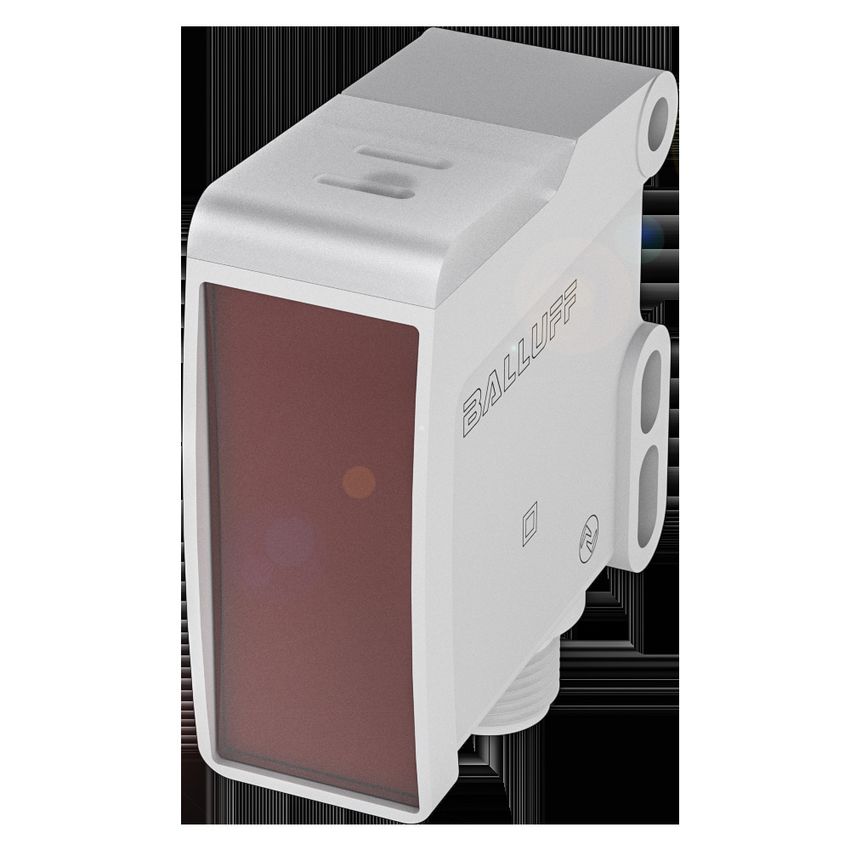
BOS R254K-UUI-LH10-S4
         Betriebsanleitung

                  deutsch
www.balluff.com
BOS R254K-UUI-LH10-S4
Optoelektronische Sensoren

                   1   Zu dieser Anleitung                                               4
                       1.1    Gültigkeit                                                 4
                       1.2    Mitgeltende Dokumente                                      4
                       1.3    Verwendete Symbole und Konventionen                        4
                       1.4    Bedeutung der Warnhinweise                                 4
                       1.5    Verwendete Fachbegriffe und Abkürzungen                    4

                   2   Sicherheitshinweise                                               5
                       2.1    Bestimmungsgemäße Verwendung                               5
                       2.2    Vernünftigerweise vorhersehbare Fehlanwendung              5
                       2.3    Allgemeine Sicherheitshinweise                             5

                   3   Lieferumfang, Transport und Lagerung                              6
                       3.1    Lieferumfang                                               6
                       3.2    Transport                                                  6
                       3.3    Lagerbedingungen                                           6

                   4   Produktbeschreibung                                              7
                       4.1    Funktion                                                   7
                       4.2    Anzeigeelemente                                            7
                       4.3    Bedruckung                                                 7

                   5   Einbau und Anschluss                                              8
                       5.1    Einbau                                                     8
                       5.2    Elektrischer Anschluss                                     8
                       5.3    Schirmung und Kabelverlegung                               8

                   6   Inbetriebnahme und Betrieb                                        9
                       6.1    Inbetriebnahme                                             9
                       6.2    Betrieb                                                    9
                       6.3    Hinweise zum Betrieb                                       9
                       6.4    Reinigung                                                  9
                       6.5    Wartung                                                    9

                   7   IO-Link-Schnittstelle                                            10

                   8   Reparatur und Entsorgung                                         11
                       8.1    Reparatur                                                 11
                       8.2    Entsorgung                                                11

                   9   Technische Daten                                                 12
                       9.1    Allgemeine Merkmale                                       12
                       9.2    Umgebungsbedingungen                                      12
                       9.3    Erfassungsbereich/Messbereich                             12
                       9.4    Elektrische Merkmale                                      12
                       9.5    Elektrischer Anschluss                                    12
                       9.6    Ausgang/Schnittstelle                                     12
                       9.7    Material                                                  13
                       9.8    Mechanische Merkmale                                      13
                       9.9    Diagramme und Anfahrkurven                                13
                       9.10   Zulassungen und Kennzeichnungen                           13

 www.balluff.com                                                              deutsch        3
BOS R254K-UUI-LH10-S4
Optoelektronische Sensoren
1 Zu dieser Anleitung
1.1 Gültigkeit 1.4 Bedeutung der Warnhinweise
Diese Anleitung stellt alle benötigten Informationen bereit Beachten Sie unbedingt die Warnhinweise in dieser
zum sicheren Gebrauch des Sensors BOS R254K-… mit Anleitung und die beschriebenen Maßnahmen zur
analoger Strom- sowie mit IO-Link-Schnittstelle. Vermeidung von Gefahren.
Sie gilt für folgende Typen: Die verwendeten Warnhinweise enthalten verschiedene
– BOS R254K-UUI-LH10-S4 Signalwörter und sind nach folgendem Schema aufgebaut:
Bestellcode: BOS0285
Lichttaster mit einstellbarer Hintergrundausblendung SIGNALWORT
Lesen Sie diese Anleitung und die mitgeltenden Doku- Art und Quelle der Gefahr
mente vollständig, bevor Sie das Produkt installieren und Folgen bei Nichtbeachtung der Gefahr
betreiben. ► Maßnahmen zur Gefahrenabwehr
Originalbetriebsanleitung Die Signalwörter bedeuten im Einzelnen:
Diese Anleitung wurde in Deutsch erstellt. Andere Sprach-
versionen sind Übersetzungen dieser Anleitung. VORSICHT
© Copyright 2021, Balluff GmbH Das allgemeine Warnsymbol in Verbindung mit dem
Alle Inhalte sind urheberrechtlich geschützt. Alle Rechte, Signalwort VORSICHT kennzeichnet eine Gefahr, die zu
einschließlich der Vervielfältigung, Veröffentlichung, Bear- leichten oder mittelschweren Verletzungen führen
beitung und Übersetzung, bleiben vorbehalten. kann.
1.2 Mitgeltende Dokumente GEFAHR
Das allgemeine Warnsymbol in Verbindung mit dem
Weitere Informationen zu diesem Produkt finden Sie unter Signalwort GEFAHR kennzeichnet eine Gefahr, die unmit-
www.balluff.com auf der Produktseite z. B. in folgenden telbar zum Tod oder zu schweren Verletzungen führt.
Dokumenten:
– Datenblatt
– Konformitätserklärung 1.5 Verwendete Fachbegriffe und Abkürzungen
– Entsorgung
SIO Standard Input Output
1.3 Verwendete Symbole und Konventionen
Einzelne Handlungsanweisungen werden durch ein
vorangestelltes Dreieck angezeigt.
► Handlungsanweisung 1
Handlungsabfolgen werden nummeriert dargestellt:
1. Handlungsanweisung 1
2. Handlungsanweisung 2
Zahlen ohne weitere Kennzeichnung sind Dezimalzahlen
(z. B. 23). Hexadezimale Zahlen werden mit vorangestell-
tem 0x dargestellt (z. B. 0x12AB).
Hinweis, Tipp
Dieses Symbol kennzeichnet allgemeine Hinweise.
4 deutschBOS R254K-UUI-LH10-S4
Optoelektronische Sensoren
2 Sicherheitshinweise
2.1 Bestimmungsgemäße Verwendung
Der optoelektronische Sensor BOS bildet zusammen mit
einer Maschinensteuerung (z. B. SPS) ein Erkennungssys-
tem. Es wird zu seiner Verwendung in eine Maschine oder
Anlage eingebaut und ist für den Einsatz im Industriebe-
reich vorgesehen.
Die einwandfreie Funktion gemäß den Angaben in den
technischen Daten wird nur mit geeignetem original Balluff
Zubehör zugesichert, die Verwendung anderer Komponen-
ten bewirkt Haftungsausschluss.
Eine nichtbestimmungsgemäße Verwendung ist nicht
zulässig und führt zum Verlust von Gewährleistungs- und
Haftungsansprüchen gegenüber dem Hersteller.
2.2 Vernünftigerweise vorhersehbare
Fehlanwendung
Das Produkt ist für folgende Anwendungen und Bereiche
nicht bestimmt und darf dort nicht eingesetzt werden:
– in sicherheitsgerichteten Anwendungen, in denen die
Personensicherheit von der Gerätefunktion abhängt
– in explosionsgefährdeten Bereichen
2.3 Allgemeine Sicherheitshinweise
Tätigkeiten wie Einbau, Anschluss und Inbetriebnahme
dürfen nur durch geschulte Fachkräfte erfolgen.
Eine geschulte Fachkraft ist, wer aufgrund seiner fachli-
chen Ausbildung, seiner Kenntnisse und Erfahrungen
sowie seiner Kenntnisse der einschlägigen Bestimmungen
die ihm übertragenen Arbeiten beurteilen, mögliche Gefah-
ren erkennen und geeignete Sicherheitsmaßnahmen treffen
kann.
Der Betreiber hat die Verantwortung, dass die örtlich
geltenden Sicherheitsvorschriften eingehalten werden.
Insbesondere muss der Betreiber Maßnahmen treffen,
dass bei einem Defekt des Produkts keine Gefahren für
Personen und Sachen entstehen können.
Das Produkt darf nicht geöffnet, umgebaut oder verändert
werden. Bei Defekten und nichtbehebbaren Störungen des
Produkts ist dieses außer Betrieb zu nehmen und gegen
unbefugte Benutzung zu sichern.
Dies ist ein Produkt der Laserklasse 1 (gem. IEC 60825-
1:2014), für das keine weiteren Schutzmaßnahmen erfor-
derlich sind. Trotzdem muss vermieden werden, direkt in
den Laserstrahl zu blicken, um vorübergehende Irritationen
der Augen zu vermeiden.
Die Verwendung von Bedienelementen oder die Durchfüh-
rung von Einstellungen oder Verfahren, die nicht in dieser
Anleitung beschrieben sind, kann zu einer gefährlichen
Strahlenbelastung führen.
www.balluff.com deutsch 5BOS R254K-UUI-LH10-S4
Optoelektronische Sensoren
3 Lieferumfang, Transport und Lagerung
3.1 Lieferumfang
– Sensor
– Montageanleitung
Zubehör ist nicht im Lieferumfang enthalten und deshalb
getrennt zu bestellen.
Empfohlenes Zubehör finden Sie unter
www.balluff.com auf der Produktseite.
3.2 Transport
► Produkt in Originalverpackung bis zum Verwendungs-
ort transportieren.
3.3 Lagerbedingungen
► Produkt in Originalverpackung lagern.
► Umgebungsbedingungen beachten (siehe Umge-
bungsbedingungen auf Seite 12).
6 deutschBOS R254K-UUI-LH10-S4
Optoelektronische Sensoren
4 Produktbeschreibung
49.50
20.40
4.30 LED 2 LED 1
Scheibe Ø 4.4
0
Optische Achse
Empfänger
50.20
37
16.60
Optische Achse
3
Sender
14
10.10
0.70
5
9.30
4.70
M12x1
Bild 4-1: Abmessungen, Aufbau und Funktion
4.1 Funktion 4.3 Bedruckung
Dieses Gerät unterstützt Condition-Monitoring-
Funktionen. Für Details siehe Dokument IO-Link-
Konfiguration unter www.balluff.com auf der 1) 2)
Produktseite.
3)
Bei einem Lichttaster mit einstellbarer Hintergrundausblen-
dung wird das Sendelicht vom Objekt reflektiert und im
Empfänger ausgewertet. Die Hintergrundausblendung
ermöglicht eine nahezu objektunabhängige Erkennung im
Erfassungsbereich.
4.2 Anzeigeelemente
LED 1 (Betriebszustand und Kommunikation)
Signal Bedeutung 1)
Bestellcode
Rot statisch Allgemeiner Fehler 2)
Seriennummer
3)
Typ
Grün wechselnd mit IO-Link-Kommunikation ist aktiv.
LED aus im Verhält- Das Gerät ist bereit. Bild 4-2: Bedruckung (Beispiel)
nis 10:1, 1 s Periode
Grün statisch Das Gerät ist bereit.
Tab. 4-1: LED 1
LED 2 (Indikation/Warnung/Teach/Ping)
Siehe Dokument IO-Link-Konfiguration unter
www.balluff.com auf der Produktseite.
www.balluff.com deutsch 7BOS R254K-UUI-LH10-S4
Optoelektronische Sensoren
5 Einbau und Anschluss
5.1 Einbau 5.2 Elektrischer Anschluss
Abmessungen siehe Bild 4-1 auf Seite 7. 1
2 4
VORSICHT
3
Sichtbare Laserstrahlung
Bild 5-2: Steckerbild (Draufsicht auf M12-Stecker am BOS)
Beim Blick in den Laserstrahl ist eine vorübergehende
Blendung und Irritation der Augen möglich. Die Verwen-
dung von Bedienelementen oder die Durchführung von Pin Signal
Einstellungen oder Verfahren, die nicht in dieser Anlei- 1 L+ (Betriebsspannung +, SIO 10…30 V,
tung beschrieben sind, kann zu einer gefährlichen IO-Link 18…30 V)
Strahlenbelastung führen. 2 I/Q (Digitaler Eingang / digitaler Ausgang / analo-
► Sensor so montieren, dass auch während des Be- ger Ausgang)
triebs kein Blick in den Laserstrahl möglich ist.
3 L− (Betriebsspannung −)
► Vorgaben dieser Anleitung berücksichtigen.
4 C/Q (IO-Link-Kommunikation / digitaler Ausgang
im SIO-Mode)
Der Sensor kann mit zwei M4 Schrauben befestigt werden. Tab. 5-1: Pinbelegung
Steckerabgangsrichtung:
Werkseinstellung
– Modus: SIO-Mode
– Betriebsmodus Objekterkennung: Standard
– PIN 2: Schaltausgang Gegentakt (push-pull)
– PIN 4: Schaltausgang Gegentakt (push-pull)
Siehe auch Dokument IO-Link-Konfiguration unter
www.balluff.com auf der Produktseite.
5.3 Schirmung und Kabelverlegung
Kabellänge
Für den IO-Link-Betrieb beträgt die maximale Kabellänge
Bild 5-1: Beispielbild bei Verwendung mit gewinkeltem Steckverbin-
der
20 m.
8 deutschBOS R254K-UUI-LH10-S4
Optoelektronische Sensoren
6 Inbetriebnahme und Betrieb
6.1 Inbetriebnahme 6.2 Betrieb
GEFAHR VORSICHT
Unkontrollierte Systembewegungen Sichtbare Laserstrahlung
Bei der Inbetriebnahme und wenn der Sensor Teil eines Beim Blick in den Laserstrahl ist eine vorübergehende
Regelsystems ist, dessen Parameter noch nicht Blendung und Irritation der Augen möglich. Die Verwen-
eingestellt sind, kann das System unkontrollierte dung von Bedienelementen oder die Durchführung von
Bewegungen ausführen. Dadurch können Personen Einstellungen oder Verfahren, die nicht in dieser Anlei-
gefährdet und Sachschäden verursacht werden. tung beschrieben sind, kann zu einer gefährlichen
► Personen müssen sich von den Gefahrenbereichen Strahlenbelastung führen.
der Anlage fernhalten. ► Nicht in den Laserstrahl blicken!
► Inbetriebnahme nur durch geschultes Fachpersonal. ► Vorgaben dieser Anleitung berücksichtigen.
► Sicherheitshinweise des Anlagen- oder Systemher-
stellers beachten. Zum Betrieb sind keine weiteren Schutzmaßnahmen
erforderlich (Laserklasse 1 gem. IEC 60825-1:2014).
VORSICHT 6.3 Hinweise zum Betrieb
Sichtbare Laserstrahlung – Funktion des Sensors und aller damit verbundenen
Beim Blick in den Laserstrahl ist eine vorübergehende Komponenten regelmäßig prüfen.
Blendung und Irritation der Augen möglich. Die Verwen- – Bei Funktionsstörungen den Sensor außer Betrieb
dung von Bedienelementen oder die Durchführung von nehmen.
Einstellungen oder Verfahren, die nicht in dieser Anlei- – Anlage gegen unbefugte Benutzung sichern.
tung beschrieben sind, kann zu einer gefährlichen – Befestigung prüfen und ggf. nachziehen.
Strahlenbelastung führen.
► Nicht in den Laserstrahl blicken!
6.4 Reinigung
► Vorgaben dieser Anleitung berücksichtigen.
Die Scheibe möglichst frei von Verschmutzung (Staub,
etc.) halten und nicht berühren (Fingerabdrücke).
1. Anschlüsse auf festen Sitz und richtige Polung prüfen.
Beschädigte Anschlüsse tauschen. Verschmutzung entfernen
2. System einschalten. ► Die Scheibe mit einem fusselfreien Tuch und Alkohol
3. Messwerte und einstellbare Parameter prüfen und ggf. (Ethanol, Isopropanol) abwischen.
den Sensor neu ausrichten und einstellen.
6.5 Wartung
Insbesondere nach dem Austausch des Sensors Das Produkt ist wartungsfrei.
oder der Reparatur durch den Hersteller die
korrekten Werte prüfen.
www.balluff.com deutsch 9BOS R254K-UUI-LH10-S4
Optoelektronische Sensoren
7 IO-Link-Schnittstelle
Das IO-Link-Gerät unterstützt die in diesem Kapitel aufge-
führten Funktionen.
Für weitere Informationen siehe Dokument IO-
Link-Konfiguration unter www.balluff.com auf
der Produktseite.
Primäre Funktionen
– Identifikation (Identification)
– Geräteerkennung (Device Discovery)
– Schaltprofile (Switching Profiles)
– Transmitter Lebenszeit Information (Transmitter Lifetime
Info)
– Sensor-Betriebsarten (Sensor Operating Modes)
– Signalqualität (Signal Quality)
Sekundäre Funktionen
– Externe Signalausblendung (External Signal Blanking)
– Signalverzögerung (Signal Delay)
– Signalgeschwindigkeitsüberwachung (Signal Speed
Monitor)
– Schaltzähler (Switching Counter)
– Grundlegende Statistik (Basic Statistics)
– Logische Blöcke (Logic Blocks)
– Betriebsstundenzähler (Operating Hours Counter)
– Betriebsstartzähler (Boot Cycle Counter)
– Spannungs- und Stromüberwachung (Voltage and
Current Monitoring)
– Status extremer Umweltbedingung (Extreme Environ-
ment Status)
– Interne Temperatur (Internal Temperature)
– Neigungsdetektion und Einstellhilfe (Inclination and
Installation Aid)
– Vibrationsdetektion (Vibration)
– Feuchtigkeitsdetektion (Humidity)
– Speichernutzungsüberwachung (Storage Usage
Monitoring)
Systemfunktionen
– Gerätestatus und detailierter Gerätestatus (Device
Status and Detailed Device Status)
– Diagnoseunterdrückung (Diagnosis Suppression)
– Resetbefehle (Reset Commands)
– Variantenkonfiguration (Variant Configuration)
– Pinzuweisung (Pin Assignment)
– Bedeutung der LED-Zustände und Konfiguration (LED
Meaning and Configuration)
– Prozessdateninformation und -konfiguration (Process
Data Info and Configuration)
– Profilcharakteristik (Profile Characteristic)
– Gerätezugriffssperren (Device Access Locks)
– Parametermanager (Parameter Manager)
10 deutschBOS R254K-UUI-LH10-S4
Optoelektronische Sensoren
8 Reparatur und Entsorgung
8.1 Reparatur
Reparaturen am Produkt dürfen nur von Balluff durchge-
führt werden.
Sollte das Produkt defekt sein, nehmen Sie Kontakt mit
unserem Service-Center auf.
8.2 Entsorgung
► Befolgen Sie die nationalen Vorschriften zur Entsor-
gung.
Weitere Informationen finden Sie unter
www.balluff.com auf der Produktseite.
www.balluff.com deutsch 11BOS R254K-UUI-LH10-S4
Optoelektronische Sensoren
9 Technische Daten
Die Angaben sind typische Werte bei 24 V DC und Raum- 9.4 Elektrische Merkmale
temperatur.
Der Sensor ist sofort betriebsbereit, die volle Genauigkeit Betriebsspannung
wird nach der Warmlaufphase erreicht. SIO 10…30 V DC
IO-Link 18…30 V DC
Weitere Daten finden Sie unter www.balluff.com Bemessungsbetriebsspannung 24 V DC
auf der Produktseite. Ue
Bemessungsbetriebsstrom Ie 100 mA
Leerlaufstrom Io bei Ue ≤ 30 mA
9.1 Allgemeine Merkmale
Bemessungsisolationsspan- 75 V DC
Lichtsender Laser nung Ui
Bereitschaftsverzug tv 300 ms
Lichtart Rotlicht
Lastkapazität bei Ue ≤ 100 nF
Wellenlänge 655 nm
Reststrom Ir ≤ 500 μA
Strahlcharakteristik Fokus typisch bei
400 mm Restwelligkeit (% von Ue) ≤ 10 %
Gebrauchskategorie DC13 Schaltfrequenz
Laserklasse nach 1 Standard mode 250 Hz
IEC 60825-1:2014 Speed mode 500 Hz
Mittlere Leistung Po ≤ 280 μW Schutzklasse II
Pulsdauer t ≤ 100 μs Spannungsfall Ud bei Ie ≤ 2,5 V
Pulsfrequenz Kurzschlussschutz ja
Standard mode 500 Hz Vertauschmöglichkeit geschützt ja
Speed mode 1000 Hz
Verpolungssicher ja
9.2 Umgebungsbedingungen
9.5 Elektrischer Anschluss
Umgebungstemperatur −10…+70 °C
Anschluss Stecker M12x1
Lagertemperatur −10…+70 °C
Anzahl Pins 4
Schutzart nach IEC 60529 (in IP67, IP69K
verschraubtem Zustand)
9.6 Ausgang/Schnittstelle
Fremdlicht ≤ 10 kLux
Ausgang Pin 4 (umschaltbar) Schaltausgang/IO-Link
9.3 Erfassungsbereich/Messbereich Schaltausgang Pin 4 Gegentakt
Reichweite Sn ≤ 250 mm Ein-/Ausgang Pin 2 (umschalt- Schaltausgang/Analog-
bar) ausgang Strom/digitaler
Reichweite S einstellbar Eingang
Temperaturdrift (% von Sn) ≤ 10 % Schaltausgang Pin 2 (umschalt- PNP/NPN/Gegentakt
Lichtfleckgröße bei 200 mm 1,3 × 0,4 mm bar)
Analogausgang Pin 2 4…20 mA
Schaltfunktion (umschaltbar) Schließer/Öffner
(NO/NC)
Schnittstelle IO-Link
Version 1.1
Baud-Rate COM3 (230,4 kBaud)
12 deutschBOS R254K-UUI-LH10-S4
Optoelektronische Sensoren
9 Technische Daten (Fortsetzung)
9.7 Material Lichtfleckgröße in Abhängigkeit vom Objektabstand
Aktive Fläche PA PACM 12
Lichtfleckgröße [mm]
3.0
Gehäusematerial PA 12 Lichtfleckgröße horizontal [mm]
2.5
Kontakte vergoldet
2.0
9.8 Mechanische Merkmale
1.5
Befestigung 2 × Schraube M4
1.0
Abmessungen (B × H × L) 20,4 × 50,2 × 49,5 mm
Lichtfleckgröße vertikal [mm]
0.5
9.9 Diagramme und Anfahrkurven
0.0
0 25 50 75 100 125 150 175 200 225 250
Schaltabstand-Abweichung in Abhängigkeit vom Objektabstand [mm]
Objektabstand bei unterschiedlichen Bild 9-3: Lichtfleckdurchmesser
Remissionsgraden
Kleinstes erkennbares Teil in Abhängigkeit vom
Sr max. [%]
4 Objektabstand
20 % Remission
2
Kleinteilgröße [mm]
5 % Remission 0.25
0
90 % Remission 0.20
-2
-4 Nylondraht (schwarz)
0.15
-6
Kupferdraht
-8 0.10
-10
0 50 100 150 200 250 300 0.05
Objektabstand [mm]
Nr. 948192-726 DE ∙ 01.131110 ∙ F21; Änderungen vorbehalten.Ersetzt L20.
Bild 9-1: Schaltabstand-Abweichung 0.00
0 25 50 75 100 125 150 175 200 225 250
Objektabstand [mm]
Anfahrkurve mit Einschaltpunkt von linker oder
rechter Seite Bild 9-4: Kleinstes erkennbares Teil
2.5 9.10 Zulassungen und Kennzeichnungen
Seitlicher Schaltpunkt [mm]
2.0
Nur zur Verwendung in NFPA 79-Anwen-
1.5 dungen.
1.0 Näherungsschalter dürfen nur mit einem
20 % Remission
0.5 R/C-Kabel (CYJV2) mit geeigneten
5 % Remission Nennwerten angeschlossen werden.
0.0
90 % Remission
-0.5
Mit dem CE-Zeichen bestätigen wir,
-1.0
dass unsere Produkte den
-1.5 Anforderungen der aktuellen
-2.0 EU-Richtlinie entsprechen.
-2.5
0 50 100 150 200 250
Objektabstand [mm]
Nähere Informationen zu Richtlinien, Zulassungen
Bild 9-2: Anfahrkurve und Normen finden Sie unter www.balluff.com
auf der Produktseite.
www.balluff.com deutsch 13BOS R254K-UUI-LH10-S4
User’s Guide
englishwww.balluff.com
BOS R254K-UUI-LH10-S4
Photoelectric Sensors

                   1   About this guide                                           4
                       1.1    Validity                                            4
                       1.2    Other applicable documents                          4
                       1.3    Symbols and conventions                             4
                       1.4    Explanation of the warnings                         4
                       1.5    Technical terms and abbreviations used              4

                   2   Safety notes                                               5
                       2.1    Intended use                                        5
                       2.2    Reasonably foreseeable misuse                       5
                       2.3    General safety notes                                5

                   3   Scope of delivery, transport and storage                   6
                       3.1    Scope of delivery                                   6
                       3.2    Transport                                           6
                       3.3    Storage conditions                                  6

                   4   Product description                                        7
                       4.1    Function                                            7
                       4.2    Display elements                                    7
                       4.3    Labeling                                            7

                   5   Installation and connection                                8
                       5.1    Installation                                        8
                       5.2    Electrical connection                               8
                       5.3    Shielding and cable routing                         8

                   6   Startup and operation                                      9
                       6.1    Startup                                             9
                       6.2    Operation                                           9
                       6.3    Operating notes                                     9
                       6.4    Cleaning                                            9
                       6.5    Maintenance                                         9

                   7   IO-Link interface                                         10

                   8   Repair and disposal                                       11
                       8.1    Repair                                             11
                       8.2    Disposal                                           11

                   9   Technical data                                            12
                       9.1    General features                                   12
                       9.2    Ambient conditions                                 12
                       9.3    Detection range/Measuring range                    12
                       9.4    Electrical data                                    12
                       9.5    Electrical connection                              12
                       9.6    Output / Interface                                 12
                       9.7    Materials                                          13
                       9.8    Mechanical features                                13
                       9.9    Diagrams and approach curves                       13
                       9.10   Approvals and designations                         13

 www.balluff.com                                                       english        3
BOS R254K-UUI-LH10-S4
Photoelectric Sensors
1 About this guide
1.1 Validity 1.4 Explanation of the warnings
This guide provides all of the information required to safely Always observe the warnings in these instructions and the
use the BOS R254K-… sensor with analog current and measures described to avoid hazards.
IO-Link interface. The warnings used here contain various signal words and
It applies to the following models: are structured as follows:
– BOS R254K-UUI-LH10-S4
Order code: BOS0285 SIGNAL WORD
Diffuse sensor with adjustable background suppression
Type and source of the hazard
Read this guide and the other applicable documents Consequences if not complied with
completely before installing and operating the product. ► Measures to avoid hazards
Original User’s Guide The individual signal words mean:
This guide was created in German. Other language
versions are translations of this guide. CAUTION
© Copyright 2021, Balluff GmbH The general warning symbol together with the signal
All content is protected by copyright. All rights reserved, word CAUTION indicates a hazard which can lead to
including the right to reproduce, publish, edit and translate slight or moderate injuries.
this document.
DANGER
1.2 Other applicable documents The general warning symbol in conjunction with the
signal word DANGER identifies a hazard which, if not
Additional information about this product can be found at avoided, will certainly result in death or serious
www.balluff.com on the product page, e.g. in the injuries.
following documents:
– Data sheet
– Declaration of Conformity 1.5 Technical terms and abbreviations used
– Disposal
SIO Standard Input Output
1.3 Symbols and conventions
Individual action instructions are indicated by a
preceding triangle.
► Instruction 1
Action sequences are numbered consecutively:
1. Instruction 1
2. Instruction 2
Numbers unless otherwise indicated are decimals
(e.g. 23). Hexadecimal numbers are represented with a
preceding 0x (e.g. 0x12AB).
Note, tip
This symbol indicates general notes.
4 englishBOS R254K-UUI-LH10-S4 Photoelectric Sensors 2 Safety notes 2.1 Intended use The BOS optoelectronic sensor, together with a machine controller (e.g. PLC), comprises a recognition system. It is intended to be installed into a machine or system and used in the industrial sector. Flawless function in accordance with the specifications in the technical data is ensured only when using suitable original Balluff accessories. Use of any other components will void the warranty. Non-approved use is not permitted and will result in the loss of warranty and liability claims against the manufacturer. 2.2 Reasonably foreseeable misuse The product is not intended for the following applications and areas and may not be used there: – In safety-oriented applications in which personal safety depends on the device function – In explosive atmospheres 2.3 General safety notes Activities such as installation, connection and commissioning may only be carried out by qualified personnel. Qualified personnel are persons whose technical training, knowledge and experience as well as knowledge of the relevant regulations allow them to assess the work assigned to them, recognize possible hazards and take appropriate safety measures. The operator is responsible for ensuring that local safety regulations are observed. In particular, the operator must take steps to ensure that a defect in the product will not result in hazards to persons or equipment. The product must not be opened, modified or changed. If defects and unresolvable faults occur in the product, take it out of service and secure against unauthorized use. This is a product of Laser Class 1 (per IEC 60825-1:2014), for which no additional protection measures are required. Nevertheless, you must avoid looking directly into the laser beam to prevent temporary irritation of the eyes. Use of Controls or adjustment or performance of procedures other than those specified herein may result in hazardous radiation exposure. www.balluff.com english 5
BOS R254K-UUI-LH10-S4
    Photoelectric Sensors

    3             Scope of delivery, transport and storage

    3.1      Scope of delivery

    –     Sensor
    –     Assembly instructions
    Accessories are not included in the scope of delivery and
    must be ordered separately.

              Recommended accessories can be found at
              www.balluff.com on the product page.

    3.2      Transport

    ► Transport product to location of use in original
      packaging.

    3.3      Storage conditions

    ► Store product in original packaging.
    ► Observe ambient conditions (see Ambient conditions
      on page 12).

6                      english
BOS R254K-UUI-LH10-S4
Photoelectric Sensors
4 Product description
49.50
20.40
4.30 LED 2 LED 1
Lens Ø 4.4
0
Optical axis of receiver
50.20
37
16.60
Optical axis of emitter
3
14
10.10
0.70
5
9.30
4.70
M12x1
Fig. 4-1: Dimensions, design and function
4.1 Function 4.3 Labeling
This device supports condition monitoring
functions. For details, see document IO-Link
configuration under www.balluff.com on the 1) 2)
product page.
3)
In the case of a diffuse sensor with adjustable background
suppression, the emitted light is reflected by the object and
evaluated in the receiver. The background suppression
allows recognition in the detection range that is almost
object-independent.
4.2 Display elements
LED 1 (operating status and communication)
Signal Meaning 1)
Order code
Static red General error 2)
Serial number
3)
Type
Green alternating IO-Link communication is active.
with LED off at ratio The device is ready. Fig. 4-2: Labeling (example)
of 10:1, 1 s period
Static green The device is ready.
Tab. 4-1: LED 1
LED 2 (indication/warning/teach/ping)
See document IO-Link configuration under
www.balluff.com on the product page.
www.balluff.com english 7BOS R254K-UUI-LH10-S4
Photoelectric Sensors
5 Installation and connection
5.1 Installation 5.2 Electrical connection
For dimensions, see Fig. 4-1 on page 7. 1
2 4
CAUTION
3
Visible laser radiation
Fig. 5-2: Plug layout (top view of M12 plug on BOS)
If you look into the laser beam, temporary blinding and
irritation of the eyes is possible. Use of Controls or
adjustment or performance of procedures other than Pin Signal
those specified herein may result in hazardous radiation 1 L+ (Operating voltage +, SIO 10…30 V,
exposure. IO-Link 18…30 V)
► Locate sensor so that it is not possible to look into 2 I/Q (Digital input / digital output / analog output)
the laser beam even during operation.
3 L− (Operating voltage −)
► Observe the instructions in this manual.
4 C/Q (IO-Link communication / digital output in SIO
mode)
The sensor can be fastened with two M4 screws. Tab. 5-1: Pin assignment
Plug outlet direction:
Factory setting
– Mode: SIO mode
– Object recognition operating mode: Standard
– PIN 2: Push-pull switching output
– PIN 4: Push-pull switching output
Also see document IO-Link configuration under
www.balluff.com on the product page.
5.3 Shielding and cable routing
Cable length
For IO-Link operation, the maximum cable length is 20 m.
Fig. 5-1: Example image of use with angled connector
8 englishBOS R254K-UUI-LH10-S4
Photoelectric Sensors
6 Startup and operation
6.1 Startup 6.2 Operation
DANGER CAUTION
Uncontrolled system movement Visible laser radiation
When starting up, if the sensor is part of a closed loop If you look into the laser beam, temporary blinding and
system whose parameters have not yet been set, the irritation of the eyes is possible. Use of Controls or
system may perform uncontrolled movements. This adjustment or performance of procedures other than
could result in personal injury and equipment damage. those specified herein may result in hazardous radiation
► Persons must keep away from the system’s exposure.
hazardous zones. ► Do not look into the laser beam!
► Startup must be performed only by trained technical ► Observe the instructions in this manual.
personnel.
► Observe the safety instructions of the equipment or No additional protection measures are required (Laser
system manufacturer. Class 1 per IEC 60825-1:2014).
6.3 Operating notes
CAUTION
– Regularly check function of the sensor and all
Visible laser radiation associated components.
If you look into the laser beam, temporary blinding and – Take the sensor out of service whenever there is a
irritation of the eyes is possible. Use of Controls or malfunction.
adjustment or performance of procedures other than – Secure the system against unauthorized use.
those specified herein may result in hazardous radiation – Check fasteners and retighten if needed.
exposure.
► Do not look into the laser beam!
6.4 Cleaning
► Observe the instructions in this manual.
Keep the lens as free from soiling as possible (dust etc.)
and do not touch it (fingerprints).
1. Check connections for tightness and correct polarity.
Replace damaged connections. Remove soiling
2. Turn on the system. ► Wipe off the lens with a lint-free cloth and alcohol
3. Check measured values and adjustable parameters (ethanol, isopropanol).
and realign and adjust the sensor, if necessary.
6.5 Maintenance
Check for the correct values, especially after The product is maintenance-free.
replacing the sensor or after repair by the
manufacturer.
www.balluff.com english 9BOS R254K-UUI-LH10-S4
Photoelectric Sensors
7 IO-Link interface
The IO-Link device supports the functions listed in this
chapter.
For further information, see document IO-Link
configuration under www.balluff.com on the
product page.
Primary functions
– Identification
– Device Discovery
– Switching Profiles
– Transmitter Lifetime Info
– Sensor Operating Modes
– Signal Quality
Secondary functions
– External Signal Blanking
– Signal Delay
– Signal Speed Monitor
– Switching Counter
– Basic Statistics
– Logic Blocks
– Operating Hours Counter
– Boot Cycle Counter
– Voltage and Current Monitoring
– Extreme Environment Status
– Internal Temperature
– Inclination and Installation Aid
– Vibration
– Humidity
– Storage Usage Monitoring
System functions
– Device Status and Detailed Device Status
– Diagnosis Suppression
– Reset Commands
– Variant Configuration
– Pin Assignment
– LED Meaning and Configuration
– Process Data Info and Configuration
– Profile Characteristic
– Device Access Locks
– Parameter Manager
10 englishBOS R254K-UUI-LH10-S4
Photoelectric Sensors
8 Repair and disposal
8.1 Repair
Repairs to the product may only be performed by Balluff.
If the product is defective, contact our Service Center.
8.2 Disposal
► Observe the national regulations for disposal.
Additional information can be found at
www.balluff.com on the product page.
www.balluff.com english 11BOS R254K-UUI-LH10-S4
Photoelectric Sensors
9 Technical data
The specifications are typical values for 24 V DC at room 9.4 Electrical data
temperature.
The sensor is fully operational immediately, with full Operating voltage
accuracy after warm-up. SIO 10...30 V DC
IO-Link 18...30 V DC
Further data can be found at www.balluff.com Rated operating voltage Ue 24 V DC
on the product page. Rated operating current Ie 100 mA
No-load current Io at Ue ≤ 30 mA
9.1 General features Rated insulation voltage Ui 75 V DC
Readiness delay tv 300 ms
Light emitter Laser
Load capacity at Ue ≤ 100 nF
Light type Red light
Residual current Ir ≤ 500 μA
Wave length 655 nm
Residual ripple (% of Ue) ≤ 10%
Beam characteristic Focus typically at
Switching frequency
400 mm
Standard mode 250 Hz
Usage category DC13 Speed mode 500 Hz
Laser class per IEC 60825-1:2014 1 Protection class II
Average power Po ≤ 280 μW Voltage drop Ud at Ie ≤ 2.5 V
Pulse duration t ≤ 100 μs Short circuit protection yes
Pulse frequency Protection against miswiring yes
Standard mode 500 Hz
Polarity reversal protected yes
Speed mode 1000 Hz
9.5 Electrical connection
9.2 Ambient conditions
Connection Plug M12x1
Ambient temperature −10...+70 °C
Storage temperature −10...+70 °C Number of pins 4
Protection per IEC 60529 (when IP67, IP69K
threaded together) 9.6 Output / Interface
Ambient light ≤ 10 kLux Output pin 4 (configurable) Switching output/IO-Link
Switching output pin 4 push-pull
9.3 Detection range/Measuring range
Input/output pin 2 (configurable) Switching output/current
Range Sn ≤ 250 mm analog output/digital
input
Range S Adjustable
Switching output pin 2 PNP/NPN/push-pull
Temperature drift (% of Sn) ≤ 10% (configurable)
Light spot size at 200 mm 1.3 × 0.4 mm Analog output pin 2 4…20 mA
Switching function NO contact/NC contact
(configurable) (NO/NC)
Interface IO-Link
Version 1.1
Baud rate COM3 (230.4 kBaud)
12 englishBOS R254K-UUI-LH10-S4
Photoelectric Sensors
9 Technical data (continued)
9.7 Materials Light spot size as a function of object distance
Active surface PA PACM 12
Light spot size [mm]
3.0
Housing material PA 12 Horizontal light spot size [mm]
2.5
Contacts Gold-plated
2.0
9.8 Mechanical features
1.5
Installation 2 × screw M4
1.0
Dimensions (W × H × L) 20.4 × 50.2 × 49.5 mm
Vertical light spot size [mm]
0.5
9.9 Diagrams and approach curves
0.0
0 25 50 75 100 125 150 175 200 225 250
Switching distance variation as a function of object Object distance [mm]
distance at different remission levels Fig. 9-3: Light spot diameter
Sr max. [%]
4 Smallest detectable part as a function of object
20 % Remission
distance
2
5 % Remission
Small part size [mm]
0 0.25
90 % Remission
-2
0.20
-4
Nylon wire (black)
-6 0.15
-8 Copper wire
0.10
-10
0 50 100 150 200 250 300
Object distance [mm] 0.05
No. 948192-726 EN ∙ 01.131110 ∙ F21; subject to modification. Replaces L20.
Fig. 9-1: Switching distance variation
0.00
Approach curve with switch-on point from left or 0 25 50 75 100 125 150 175 200 225 250
Object distance [mm]
right side
Fig. 9-4: Smallest detectable part
2.5
Side switching point [mm]
2.0 9.10 Approvals and designations
1.5 For use in NFPA 79 Applications only.
1.0 Proximity Switches shall be connected
20 % Remission
0.5 only by using any R/C (CYJV2) cord,
5 % Remission having suitable ratings.
0.0
90 % Remission
-0.5
-1.0
The CE Mark verifies that our products
-1.5 meet the requirements of the current EU
-2.0 Directive.
-2.5
0 50 100 150 200 250
Object distance [mm]
Fig. 9-2: Approach curve Additional information on directives, approvals and
standards can be found at www.balluff.com on
the product page.
www.balluff.com english 13BOS R254K-UUI-LH10-S4
Notice d’utilisation
françaiswww.balluff.com
BOS R254K-UUI-LH10-S4
Capteurs optoélectroniques

                   1   À propos de cette notice                                        4
                       1.1    Validité                                                 4
                       1.2    Autres documents de référence                            4
                       1.3    Symboles et conventions utilisés                         4
                       1.4    Signification des avertissements                         4
                       1.5    Termes techniques et abréviations utilisés               4

                   2   Consignes de sécurité                                           5
                       2.1    Utilisation conforme aux prescriptions                   5
                       2.2    Mauvais usage raisonnablement prévisible                 5
                       2.3    Consignes générales de sécurité                          5

                   3   Fourniture, transport et stockage                               6
                       3.1    Fourniture                                               6
                       3.2    Transport                                                6
                       3.3    Conditions de stockage                                   6

                   4   Description du produit                                          7
                       4.1    Fonction                                                 7
                       4.2    Éléments d’affichage                                     7
                       4.3    Impression                                               7

                   5   Montage et raccordement                                         8
                       5.1    Montage                                                  8
                       5.2    Raccordement électrique                                  8
                       5.3    Blindage et pose des câbles                              8

                   6   Mise en service et fonctionnement                               9
                       6.1    Mise en service                                          9
                       6.2    Fonctionnement                                           9
                       6.3    Conseils d’utilisation                                   9
                       6.4    Nettoyage                                                9
                       6.5    Maintenance                                              9

                   7   Interface IO-Link                                              10

                   8   Réparation et élimination                                      11
                       8.1    Réparation                                              11
                       8.2    Élimination                                             11

                   9   Caractéristiques techniques                                    12
                       9.1    Caractéristiques générales                              12
                       9.2    Conditions ambiantes                                    12
                       9.3    Zone de détection / plage de mesure                     12
                       9.4    Caractéristiques électriques                            12
                       9.5    Raccordement électrique                                 12
                       9.6    Sortie / interface                                      12
                       9.7    Matériau                                                13
                       9.8    Caractéristiques mécaniques                             13
                       9.9    Diagrammes et courbes de détection                      13
                       9.10   Homologations et certifications                         13

 www.balluff.com                                                           français        3
BOS R254K-UUI-LH10-S4
Capteurs optoélectroniques
1 À propos de cette notice
1.1 Validité 1.4 Signification des avertissements
La présente notice fournit toutes les informations Respecter impérativement les avertissements de cette
nécessaires pour une utilisation sûre du capteur notice et les mesures décrites pour éviter tout danger.
BOS R254K-… avec interface courant analogique et Les avertissements utilisés comportent différents mots‑clés
interface IO-Link. et sont organisés de la manière suivante :
Il est valable pour les types suivants :
– BOS R254K-UUI-LH10-S4 MOT-CLE
Symbolisation commerciale : BOS0285
Détecteur optique avec suppression de l’arrière-plan Type et source de danger
réglable Conséquences en cas de non-respect du danger
► Mesures à prendre pour éviter le danger
Lisez entièrement la notice et les autres documents de
référence, avant d’installer et d’exploiter le produit.
Signification des mots-clés en détail :
Notice d’utilisation d’origine
PRÉCAUTION
Cette notice a été créée en allemand. Les autres versions Le symbole « Attention » accompagné du mot
de langue sont des traductions de la présente notice. PRECAUTION caractérise un danger pouvant entraîner
© Copyright 2021, Balluff GmbH des blessures de gravité légère à moyenne.
Tous les contenus sont protégés par le droit d’auteur. Tous
les droits, y compris la reproduction, la publication, DANGER
l’édition et la traduction, sont réservés. Le symbole « Attention » accompagné du mot DANGER
caractérise un danger pouvant entraîner directement la
1.2 Autres documents de référence mort ou des blessures graves.
Vous trouverez des informations complémentaires
concernant ce produit sous www.balluff.com, sur la 1.5 Termes techniques et abréviations utilisés
page produit, p. ex. dans les documents suivants :
– Fiche technique SIO Standard Input Output (Entrée/sortie standard)
– Déclaration de conformité
– Élimination
1.3 Symboles et conventions utilisés
Les instructions spécifiques sont précédées d’un
triangle.
► Instruction 1
Les instructions sont numérotées et décrites selon leur
ordre :
1. Instruction 1
2. Instruction 2
Les nombres sans autre marquage sont des nombres
décimaux (p. ex. 23). Les nombres hexadécimaux sont
représentés avec le préfixe 0x (p. ex. 0x12AB).
Conseils d’utilisation
Ce symbole caractérise des remarques générales.
4 françaisBOS R254K-UUI-LH10-S4 Capteurs optoélectroniques 2 Consignes de sécurité 2.1 Utilisation conforme aux prescriptions Couplé à une commande de machine (p. ex. API), le capteur optoélectronique BOS constitue un système d’identification. Il est monté dans une machine ou une installation et est destiné aux applications dans le domaine industriel. Son bon fonctionnement, conformément aux indications figurant dans les caractéristiques techniques, n’est garanti qu’avec les accessoires d’origine Balluff appropriés ; l’utilisation d’autres composants entraîne la nullité de la garantie. Toute utilisation inappropriée est interdite et entraîne l’annulation de la garantie et de la responsabilité du fabricant. 2.2 Mauvais usage raisonnablement prévisible Le produit n’est pas conçu pour les applications et domaines suivants et ne doit pas y être mis en œuvre : – dans des applications orientées sécurité dont la sécurité des personnes dépend de la fonction de l’appareil – dans des zones explosibles 2.3 Consignes générales de sécurité Les activités telles que le montage, le raccordement et la mise en service ne doivent être exécutées que par un personnel qualifié. Est considéré comme qualifié le personnel qui, par sa formation technique, ses connaissances et son expérience, ainsi que par ses connaissances des dispositions spécifiques régissant son travail, peut reconnaître les dangers potentiels et prendre les mesures de sécurité adéquates. Il est de la responsabilité de l’exploitant de veiller à ce que les dispositions locales concernant la sécurité soient respectées. L’exploitant doit en particulier prendre les mesures nécessaires pour éviter tout danger pour les personnes et le matériel en cas de dysfonctionnement du produit. Le produit ne doit pas être ouvert, transformé ou modifié. En cas de dysfonctionnement et de pannes du produit, celui-ci doit être mis hors service et protégé contre toute utilisation non autorisée. Il s’agit d’un produit laser de classe 1 (selon CEI 60825- 1:2014), pour lequel aucune autre mesure de protection n’est nécessaire. Néanmoins, il faut éviter de regarder directement dans le faisceau laser pour éviter une irritation temporaire des yeux. L’utilisation d’éléments de commande ou l’exécution de réglages ou de procédures autres que celles spécifiées dans la présent notice peut entraîner une exposition dangereuse aux radiations. www.balluff.com français 5
BOS R254K-UUI-LH10-S4
    Capteurs optoélectroniques

    3             Fourniture, transport et stockage

    3.1      Fourniture

    –     Capteur
    –     Notice de montage
    Les accessoires ne sont pas compris dans le matériel livré
    et doivent être commandés séparément.

              Vous trouverez les accessoires conseillés sous
              www.balluff.com, sur la page produit.

    3.2      Transport

    ► Transporter le produit dans son emballage d’origine
      jusqu’au lieu d’utilisation.

    3.3      Conditions de stockage

    ► Stocker le produit dans son emballage d’origine.
    ► Respecter les conditions ambiantes (voir Conditions
      ambiantes, page 12).

6                     français
BOS R254K-UUI-LH10-S4
Capteurs optoélectroniques
4 Description du produit
49.50
20.40
4.30 LED 2 LED 1
Vitre Ø 4.4
0
Axe optique récepteur
50.20
37
16.60
Axe optique émetteur
3
14
10.10
0.70
5
9.30
4.70
M12x1
Fig. 4-1 : Dimensions, structure et fonction
4.1 Fonction 4.3 Impression
Cet appareil supporte les fonctions de Condition
Monitoring (contrôle d’état). Pour les détails, voir le
document Configuration IO-Link sous 1) 2)
www.balluff.com, sur la page produit.
3)
Dans le cas d’un détecteur optique avec suppression de
l’arrière-plan réglable, la lumière émise est réfléchie par
l’objet et interprétée dans le récepteur. La suppression de
l’arrière-plan permet une détection quasi indépendante de
l’objet dans la zone de détection.
4.2 Éléments d’affichage
LED 1 (état de fonctionnement et communication)
Signal Signification 1)
Symbolisation commerciale
Rouge statique Erreur générale 2)
Numéro de série
3)
Type
Vert alternant avec La communication IO-Link est
LED éteinte selon un active. L’appareil est prêt. Fig. 4-2 : Impression (exemple)
rapport 10:1,
période de 1 s
Vert statique L’appareil est prêt.
Tab. 4-1 : LED 1
LED 2 (Indication/Avertissement/Apprentissage/Ping)
Voir le document Configuration IO-Link sous
www.balluff.com, sur la page produit.
www.balluff.com français 7BOS R254K-UUI-LH10-S4
Capteurs optoélectroniques
5 Montage et raccordement
5.1 Montage 5.2 Raccordement électrique
Dimensions, voir Fig. 4-1, page 7. 1
2 4
PRÉCAUTION
3
Rayonnement laser visible
Fig. 5-2 : Schéma du connecteur (vue de dessus du connecteur
Lorsque l’on regarde dans le faisceau laser, un M12 sur le BOS)
éblouissement temporaire et une irritation des yeux sont
possibles. L’utilisation d’éléments de commande ou
Broche Signal
l’exécution de réglages ou de procédures autres que
celles spécifiées dans la présent notice peut entraîner 1 L+ (tension d’emploi +, SIO 10…30 V,
une exposition dangereuse aux radiations. IO-Link 18…30 V)
► Monter le capteur de telle sorte qu’aucun regard 2 I/Q (entrée numérique / sortie numérique /
dans le faisceau laser ne soit possible, y compris sortie analogique)
pendant le fonctionnement. 3 L− (tension d’emploi −)
► Respecter les spécifications de cette notice.
4 C/Q (communication IO-Link / sortie
numérique en mode SIO)
Le capteur peut être fixé à l’aide de deux vis M4. Tab. 5-1 : Affectation des broches
Sens de départ du connecteur : Réglage usine
– Mode : mode SIO
– Mode opératoire détection d’objets : standard
– BROCHE 2 : sortie de commutation push-pull
– BROCHE 4 : sortie de commutation push-pull
Voir également le document Configuration IO-Link
sous www.balluff.com, sur la page produit.
5.3 Blindage et pose des câbles
Longueur de câble
Pour le mode IO-Link, la longueur maximale de câble est
Fig. 5-1 : Exemple d’illustration en cas d’utilisation avec connecteur de 20 m.
coudé
8 françaisBOS R254K-UUI-LH10-S4
Capteurs optoélectroniques
6 Mise en service et fonctionnement
6.1 Mise en service 6.2 Fonctionnement
DANGER PRÉCAUTION
Mouvements incontrôlés du système Rayonnement laser visible
Lors de la mise en service et lorsque le capteur fait Lorsque l’on regarde dans le faisceau laser, un
partie intégrante d’un système de régulation dont les éblouissement temporaire et une irritation des yeux sont
paramètres n’ont pas encore été réglés, des possibles. L’utilisation d’éléments de commande ou
mouvements incontrôlés peuvent survenir. De tels l’exécution de réglages ou de procédures autres que
mouvements sont susceptibles de causer des celles spécifiées dans la présent notice peut entraîner
dommages corporels et matériels. une exposition dangereuse aux radiations.
► Les personnes doivent se tenir à l’écart de la zone ► Ne pas regarder dans le rayon laser !
de danger de l’installation. ► Respecter les spécifications de cette notice.
► La mise en service ne doit être effectuée que par un
personnel qualifié. Aucune mesure de protection supplémentaire n’est
► Les consignes de sécurité de l’installation ou du nécessaire pour le fonctionnement (laser de classe 1 selon
fabricant doivent être respectées. CEI 60825-1:2014).
6.3 Conseils d’utilisation
PRÉCAUTION
– Contrôler régulièrement le fonctionnement du capteur
Rayonnement laser visible et de tous les composants associés.
Lorsque l’on regarde dans le faisceau laser, un – En cas de dysfonctionnement, mettre le capteur hors
éblouissement temporaire et une irritation des yeux sont service.
possibles. L’utilisation d’éléments de commande ou – Protéger l’installation de toute utilisation non autorisée.
l’exécution de réglages ou de procédures autres que – Contrôler la fixation, resserrer si nécessaire.
celles spécifiées dans la présent notice peut entraîner
une exposition dangereuse aux radiations.
6.4 Nettoyage
► Ne pas regarder dans le rayon laser !
► Respecter les spécifications de cette notice. La vitre doit rester, autant que possible, propre (poussières,
etc.) et ne pas la toucher (empreintes digitales).
1. Vérifier la fixation et la polarité des raccordements. Éliminer les saletés
Remplacer les raccordements endommagés. ► Essuyer la vitre à l’aide d’un chiffon non pelucheux et
2. Mettre le système en marche. d’alcool (éthanol, isopropanol).
3. Vérifier les valeurs mesurées et les paramètres
réglables et, le cas échéant, réaligner le capteur et 6.5 Maintenance
procéder à un nouveau réglage.
Le produit est sans entretien.
Vérifier l’exactitude des valeurs, en particulier
après un remplacement du capteur ou une
réparation par le fabricant.
www.balluff.com français 9BOS R254K-UUI-LH10-S4
Capteurs optoélectroniques
7 Interface IO-Link
L’appareil IO-Link supporte les fonctions mentionnées
dans ce chapitre.
Pour plus d’informations, voir le document
Configuration IO-Link sous www.balluff.com, sur
la page produit.
Fonctions primaires
– Identification (Identification)
– Détection de l’appareil (Device Discovery)
– Profils de commutation (Switching Profiles)
– Informations sur la durée de vie du transmetteur
(Transmitter Lifetime Info)
– Modes opératoires du capteur (Sensor Operating
Modes)
– Qualité de signal (Signal Quality)
Fonctions secondaires
– Suppression externe du signal (External Signal
Blanking)
– Temporisation du signal (Signal Delay)
– Surveillance de la vitesse du signal (Signal Speed
Monitor)
– Compteur de commutations (Switching Counter)
– Statistique de base (Basic Statistics)
– Blocs logiques (Logic Blocks)
– Compteur d’heures de fonctionnement (Operating
Hours Counter)
– Compteur de cycles de démarrage (Boot Cycle
Counter)
– Surveillance de la tension et du courant (Voltage and
Current Monitoring)
– État environnement extrême (Extreme Environment
Status)
– Température interne (Internal Temperature)
– Détection d’inclinaison et aide au réglage (Inclination
and Installation Aid)
– Détection de vibration (Vibration)
– Détection d’humidité (Humidity)
– Surveillance de l’utilisation de la mémoire (Storage
Usage Monitoring)
Fonctions système
– État d’appareil et état d’appareil détaillé (Device Status
and Detailed Device Status)
– Suppression du diagnostic (Diagnosis Suppression)
– Commande de réinitialisation (Reset Commands)
– Configuration des variantes (Variant Configuration)
– Affectation des broches (Pin Assignment)
– Signification des états LED et configuration (LED
Meaning and Configuration)
– Informations sur les données de processus et la
configuration (Process Data Info and Configuration)
– Caractéristique du profil (Profile Characteristic)
– Verrouillages d’accès à l’appareil (Device Access
Locks)
– Gestionnaire de paramètres (Parameter Manager)
10 françaisBOS R254K-UUI-LH10-S4
Capteurs optoélectroniques
8 Réparation et élimination
8.1 Réparation
Les réparations du produit ne peuvent être effectuées que
par Balluff.
Si le produit est défectueux, veuillez contacter notre centre
de service.
8.2 Élimination
► Pour l’élimination des déchets, se conformer aux
dispositions nationales.
Vous trouverez des informations complémentaires
sous www.balluff.com, sur la page produit.
www.balluff.com français 11BOS R254K-UUI-LH10-S4
Capteurs optoélectroniques
9 Caractéristiques techniques
Les indications sont des valeurs typiques à 24 V DC et à la 9.4 Caractéristiques électriques
température ambiante.
Le capteur est immédiatement opérationnel et une Tension d’emploi
précision maximale est obtenue après la phase SIO 10…30 V DC
d’échauffement. IO-Link 18…30 V DC
Tension d’emploi nominale Ue 24 V DC
Vous trouverez des informations supplémentaires Courant d’emploi nominal Ie 100 mA
sous www.balluff.com, sur la page produit.
Courant à vide Io à Ue ≤ 30 mA
Tension d’isolement nominale Ui 75 V DC
9.1 Caractéristiques générales Retard à l’amorçage tv 300 ms
Capacité de charge à Ue ≤ 100 nF
Émetteur de lumière Laser
Courant résiduel Ir ≤ 500 μA
Type de lumière Lumière rouge
Ondulation résiduelle (% de Ue) ≤ 10 %
Longueur d’onde 655 nm
Fréquence de commutation
Caractéristique faisceau Focalisation typique
Mode standard 250 Hz
à 400 mm
Mode « speed » 500 Hz
Catégorie d’utilisation DC13
Classe de protection II
Classe laser selon 1
Chute de tension Ud pour Ie ≤ 2,5 V
CEI 60825-1:2014
Puissance moyenne Po ≤ 280 μW Protection contre les courts- Oui
circuits
Durée d’impulsion t ≤ 100 μs
Protection contre l’interversion Oui
Fréquence d’impulsion
Protection contre l’inversion de Oui
Mode standard 500 Hz
polarité
Mode « speed » 1000 Hz
9.5 Raccordement électrique
9.2 Conditions ambiantes
Raccordement Connecteur mâle M12x1
Température ambiante −10…+70 °C
Nombre de broches 4
Température de stockage −10…+70 °C
Classe de protection selon IP67, IP69K
CEI 60529 (à l’état vissé) 9.6 Sortie / interface
Lumière ambiante ≤ 10 kLux Sortie broche 4 (commutable) Sortie de commutation/
IO-Link
9.3 Zone de détection / plage de mesure Sortie de commutation Push-pull
broche 4
Portée Sn ≤ 250 mm
Entrée/sortie broche 2 Sortie de commutation /
Portée S réglable (commutable) Sortie analogique
Dérive thermique (% de Sn) ≤ 10 % courant / Entrée
numérique
Taille du spot lumineux à 200 mm 1,3 × 0,4 mm
Sortie de commutation PNP/NPN/push-pull
broche 2 (commutable)
Sortie analogique broche 2 4…20 mA
Fonction de contact À fermeture/ouverture
(commutable) (NO/NF)
Interface IO-Link
Version 1.1
Vitesse de transmission en COM3 (230,4 kBaud)
bauds
12 françaisSie können auch lesen