(D) Bedienungs-/Montageanleitung (GB) Operation / Installation Manual - VNS 102V2
←
→
Transkription von Seiteninhalten
Wenn Ihr Browser die Seite nicht korrekt rendert, bitte, lesen Sie den Inhalt der Seite unten

(D) Bedienungs-/Montageanleitung
                               (GB) Operation / Installation Manual

                                                                                             VNS 102V2

Funkwerk plettac electronic GmbH
Würzburger Str. 150
D 90766 Fürth
Tel.: 0911/75884-0                                                                             43522-941.96(00)
Fax: 0911/75884-100                Änderungen vorbehalten/Subject to change without notice             11/2009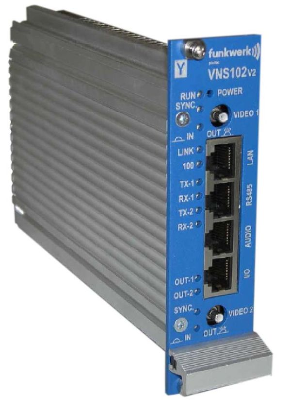
Inhaltsverzeichnis / table of contents
(D) Deutsch
Allgemeine Beschreibung                                           4
Wartung                                                           4
  Hilfe bei Störungen                                             4
  Lieferumfang:                                                   5
  Entsorgung                                                      5
Steckerbelegungen VNS 102V2                                       6
  Spannungsversorgung des VNS 102V2                               7
  LAN-Schnittstelle                                               8
  Serielle RS485 Schnittstelle                                    9
  Audio                                                          10
  Digitale I/O                                                   11
Zubehör für VNS 102V2                                            12
Inbetriebnahme / Konfiguration                                   12
  Auslieferzustand:                                              12
  Notwendiges Zubehör zur Erstinbetriebnahme / Konfiguration     12
  Inbetriebnahme und Konfiguration des VNS 102V2                 12
Technische Daten                                                 18
Maßbild VNS 102V2                                                18

(GB) English
General description                                              21
Maintenance                                                      21
  Troubleshooting                                                21
  Delivery scope:                                                22
  Disposal                                                       22
Pin assignment VNS 102V2                                         23
  Voltage supply of the VNS 102V2                                24
  LAN interface                                                  25
  Serial RS485 interface                                         26
  Audio                                                          27
  Digital I/O                                                    28
Accessories for the VNS 102V2                                    29
Commissioning/configuration                                      29
  Delivery status:                                               29
  Required accessories for initial commissioning/configuration   29
  Commissioning and configuring the VNS 102V2                    29
Technical data                                                   35
Dimension diagram VNS 102V2                                      35

VNS 102V2
                                                        2
11/2009
Alle Einstellvorgänge bei Inbetriebnahme und Service werden überwiegend über die
                Steuerschnittstelle bzw. die Web-Seite, aber immer bei geschlossenem Gerät
                ausgeführt. Das Gerät darf nur im Werk durch geschulte und autorisierte Personen
                geöffnet werden, da sonst auch mit Langzeitbeschädigungen und Ausfall des
                Kühlsystems zu rechnen ist!
                Bei Schäden durch Nichtbeachten der Bedienungsanleitung oder Öffnen des Geräts
                erlischt der Garantieanspruch.
                Für Folgeschäden wird keine Haftung übernommen!

•   Der VNS 102V2 darf nur bestimmungsgemäß eingesetzt und nicht außerhalb seiner spezifizierten
    Betriebs- und Umgebungsbedingungen betrieben werden.

•   Der VNS 102V2 darf nur von autorisiertem Fachpersonal montiert werden.

•   Geltende Sicherheitsbestimmungen und Unfallverhütungsvorschriften sind zu beachten.

•   Vor Montage- oder Servicearbeiten Betriebsspannung abschalten.

•   Bei Montage- und Servicearbeiten dürfen nur Originalteile verwendet werden.

•   Der Montageort muss sich in einer Blitz-Schutzzone LPZ 3 befinden.

•   Die vorgeschriebenen minimalen Biegeradien der Kabel müssen eingehalten werden.

•   Die vorgeschriebenen Entstörmaßnahmen sind einzuhalten

                                                                                                   VNS 102V2
                                                       3
                                                                                                     11/2009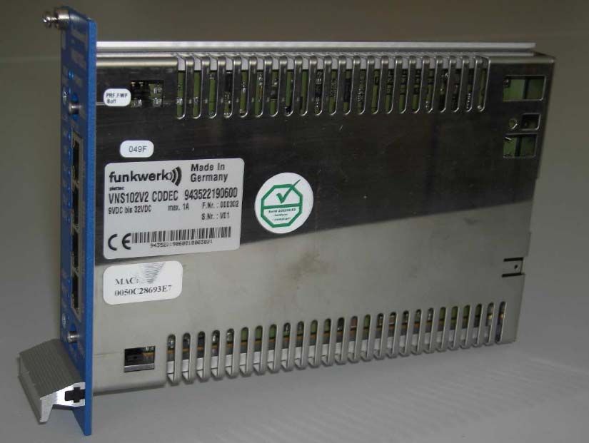
Allgemeine Beschreibung
Der VNS 102V2 ist die Weiterentwicklung des bewährten VNS102 Video Network Streamer mit 1 digitalen
Signalprozessor (DSP) und 2 Videoanschlüssen, der Videoüberwachungssysteme sehr leistungsfähig mit LAN
oder Internet unterstützt.
Die Advanced Simple Profile MPEG-4 Codierung bietet gegenüber vorher genutzten Standards bei gleicher
Netzlast erheblich bessere Bildqualität bei dynamischen Bildsequenzen. Das ist für Übertragung und
Aufzeichnung ein sehr wichtiger Vorteil.
Die Konfiguration kann über Webbrowser (HTML) und Funkwerk plettac Managementsystem p.o.s.a. erfolgen.
Bei Auftreten von Alarmen können MPEG-4 Sequenzen konfigurierbar in Länge (auch Vorgeschichte), Bildrate
und Bildqualität im lokalen Speicher aufgezeichnet werden. Das alarmauslösende Ereignis wird außerdem auch
an ein zentrales Managementsystem weitergeleitet. Livebilder und gespeicherte Sequenzen werden über LAN
in die Überwachungszentrale übertragen.
Abhängig von der Netzwerkstrategie des Kunden können von Breitband-LAN über ISDN bis hin zu GSM alle
vorhandenen Netze mit MPEG 4 „advanced“ und/oder „Standard“–Profile bei voller Auflösung genutzt werden.
Die eingesetzte Lösung lässt dem Kunden des Weiteren die Wahlmöglichkeit einer frei skalierbaren Mindest-
Bildqualität bei variabler Bildrate zur Minimierung der Netzlast.

Hinweis:
Diese Bedienungsanleitung ist nur für den Anschluss des VNS 102V2 und die ersten Schritte der
Inbetriebnahme anzuwenden. Details, Spezielle Einstellungen und Funktionshinweise sind der Technischen
Dokumentation 43522942.91 zu entnehmen.
Informationen über die Stromversorgung (TM11) sowie den Aufbau des 19“ Einschubes finden Sie in der
Montageanleitung 43435-941.23 für TM11.

Wartung
Die elektrische Sicherheit (Stromversorgung) ist regelmäßig zu überprüfen. Bei Wartungsarbeiten ist die
Stromversorgung immer auszuschalten. Zum Reinigen nur lösungsmittelfreie Reinigungsmittel drucklos
verwenden.

Hilfe bei Störungen
Keine Funktion (LED’s alle aus)             Betriebsspannung überprüfen
Kein Bild                                   Überprüfung aller Anschlüsse sowie der gesamten Konfiguration
Weitere Funktionsstörungen                  siehe Technische Dokumentation VNS 102V2

Bei weitergehenden Störungen autorisiertes Servicepersonal benachrichtigen. Bei entsprechendem Abschluß
eines Wartungsvertrages stehen im Werk kurzfristig Tauschgeräte zur Verfügung.

Funkwerk plettac electronic GmbH
Reparatureingang DE
Würzburger Straße 150
D-90766 Fürth/Bayern
Tel. 01805 671205
Fax 0911/75884-100
E-Mail: stoerung@plettac-electronics.de
http://www.cctv-systeme.com

VNS 102V2
                                                        4
11/2009
Lieferumfang:
•   VNS 102V2-Codec (19“ Einbaukassette)        Best.-Nr. 943522190600
•   CD mit ausführlicher Dokumentation und Streaming Plugin SW
•   2 Jumper
•   Bedienungs- und Montageanleitung            Best.-Nr. 435229419600

Entsorgung
Entsorgen Sie das Gerät entsprechend den geltenden gesetzlichen Vorschriften.

                                                                                VNS 102V2
                                                      5
                                                                                  11/2009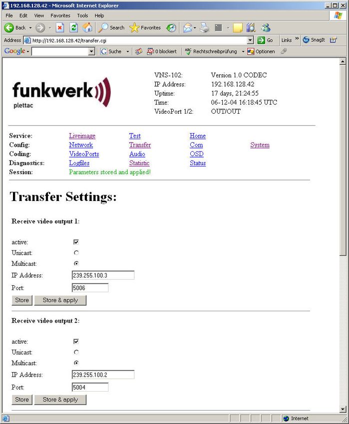
Steckerbelegungen VNS 102V2

                         RJRJ 45 „Audio“
                           45 „Audio“

                         RJRJ
                            4545 „I/O“
                               „I/O“

                                               4-poliger DIP-SWITCH

                                               PIN      1 2 3 4

VNS 102V2
                                           6
11/2009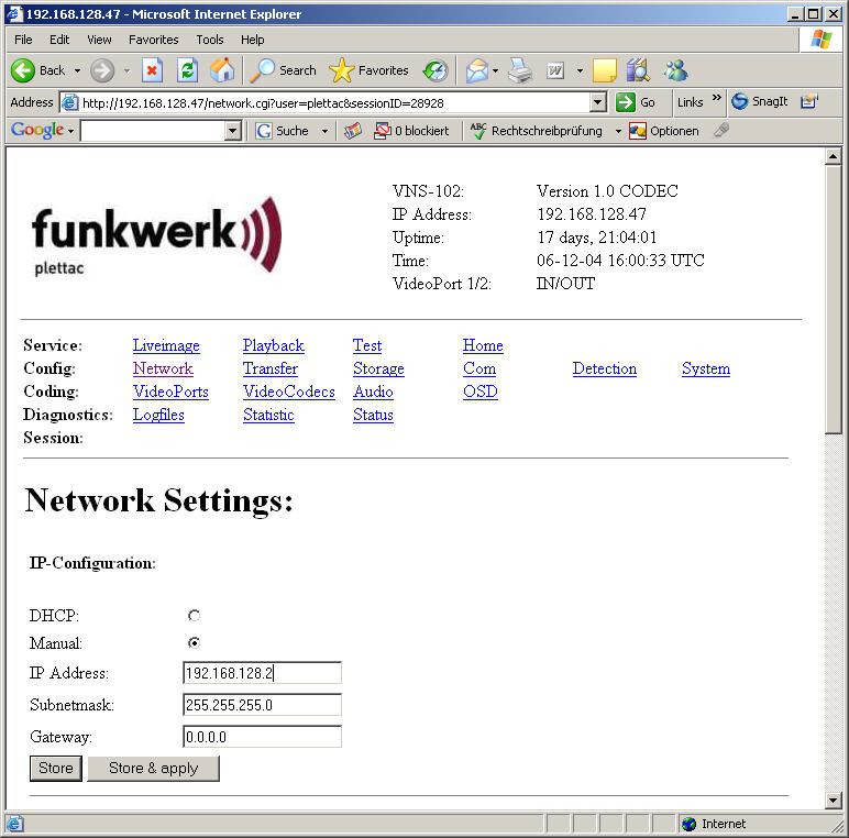
Spannungsversorgung des VNS 102V2

Die Spannungsversorgung erfolgt über den Powerstecker: auf der Rückseite des VNS 102V2.
Signal                  WAGO Stecker Pin                    Beschreibung

GND                                        1                - Pol (Ground)

UB                                         2                + Pol (Power min. 9,5 bis max. 32 VDC)

FRAME                                      3                Chassis Ground

Empfohlenes Netzteil für Einbau in 19“ Baugruppenträger: TM11 (siehe Zubehör)

                                                                                                     VNS 102V2
                                                      7
                                                                                                       11/2009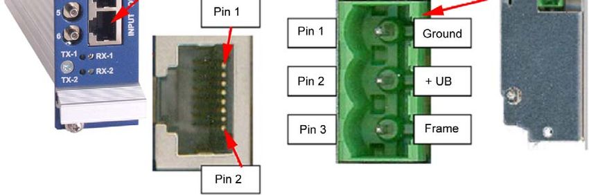
LAN-Schnittstelle
Die LAN Schnittstelle entspricht dem Standard IEEE802.1 mit 10/100Mbit (autosense) über Cat-5 Kabel
(10/100BaseT). Als LAN-Anschluss steht ein RJ45 Stecker an der Frontseite des VNS 102V2 mit der
Bezeichnung „LAN“ zur Verfügung.
Signal               RJ45 “LAN”   Pin               Signal                   RJ45 “LAN”    Pin

         TX+                       1                          TX-                           2

         RX+                       3                                                        4

                                   5                          RX-                           6

                                   7                                                        8

VNS 102V2
                                                      8
11/2009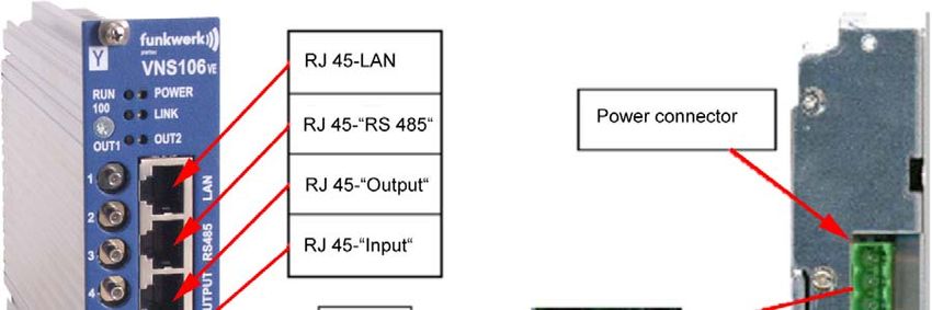
Serielle RS485 Schnittstelle
Der Anschluss beider Schnittstellenports erfolgt über einen RJ45 Stecker an der Frontseite des VNS 102V2 mit
der Bezeichnung „RS485“
                            RS485”   Pin                                          RS485”    Pin

 TX+ COM 1 (UART A)                   1                    TX- COM 1 (UART A)                2

 RX+ COM 1 (UART A)                   3                    TX+ COM 2 (UART B)                4

  TX- COM 2 (UART B)                  5                    RX- COM 1 (UART A)                6

 RX+ COM 2 (UART B)                   7                    RX- COM 2 (UART B)                8

                                                                                                   VNS 102V2
                                                       9
                                                                                                     11/2009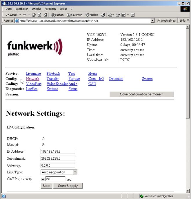
Audio
Als Ein- und Ausgangsstecker für das analoge Audiosignal wird ein RJ45 Stecker an der Frontseite des
VNS 102V2 mit der Bezeichnung „AUDIO“ verwendet.
              Signal (In)           RJ45 „AUDIO“   Pin               Beschreibung

                 R_IN                               3                Line In - rechter Kanal Signal

            AGND_AUDIO_IN1                          6                Line In - rechter Kanal GND

                 L_IN                               7                Line In - linker Kanal Signal

            AGND_AUDIO_IN2                          8                Line In - linker Kanal GND

             Signal (Out)           RJ45 „AUDIO“   Pin               Beschreibung

                R_OUT                               1                rechter Kanal Signal

        AGND_AUDIO_OUT2_X                           2                rechter Kanal GND

                L_OUT                               4                linker Kanal Signal

        AGND_AUDIO_OUT1_X                           5                linker Kanal GND

VNS 102V2
                                                         10
11/2009
Digitale I/O
Der Anschluss beider digitalen Ein- bzw. Ausgänge erfolgt über den RJ45 Stecker an der Frontseite des VNS
102V2 mit der Bezeichnung „I/O“
Signal RJ45 “I/O” Pin Signal RJ45 I/O Pin
OUT1+ (Ausgang 1, Signal) 1 OUT1- (Ausgang 2, GND) 2
IN1+ (Eingang 1, Signal) 3 OUT2+ (Ausgang 2, Signal) 4
OUT2- (Ausgang 2, GND) 5 IN1- (Eingang 1, GND) 6
IN2+ (Eingang 2, Signal) 7 IN2- (Eingang 2, GND) 8
VNS 102V2
11
11/2009Zubehör für VNS 102V2
19“ Baugruppenträger kpl. verdrahtet incl. Netzkabel und 2 Blindplatten Best.-Nr. 943525150100
Trafomodul TM11 Best.-Nr. 943435120300
Blindplatten (7 TE blau) Best.-Nr. 943525180700
Rüstsatz Kabel Best.-Nr. 943525160100
Rüstsatz Anschlußeinheit Best.-Nr. 943522190500
Rüstsatz AK 187 Best.-Nr. 943525150500
CD mit Active X (Software zur Darstellung eines Videobildes auf dem PC-Monitor) Best.-Nr. 943526110100
Rüstsatz Kaluka 1HE (Kabel-Luftkanal) Best.-Nr. 943525190100
Rüstsatz 1HE Schranklüfter Best.-Nr. xxxxxxxxxxxx
Rüstsatz Kaluka 2HE (Kabel-Luftkanal-VAZ) Best.-Nr. 941714180100
Inbetriebnahme / Konfiguration
Der VNS 102V2 darf nur mit einem geeigneten Netzteil (9,5 V DC bis 32 V DC; z.B. TM11) betrieben werden.
Alle Einstellvorgänge bei Inbetriebnahme und Service werden ausschließlich über die Steuerschnittstelle bzw.
einen WEB-Browser bei geschlossenem Gerät ausgeführt. Das Gerät darf nur im Werk durch geschulte und
autorisierte Personen geöffnet werden, da sonst auch mit Langzeitbeschädigungen und Ausfall des
Kühlsystems zu rechnen ist!
Bei den weiteren Konfigurationsschritten wird davon ausgegangen, dass sich der VNS 102V2 im
Auslieferzustand befindet.
Auslieferzustand:
Der Auslieferzustand kann mit Dip-Switch 4 und nachträglichem Einschalten der Spannungsversorgung des
VNS 102V2 hergestellt werden. Nach einmaligen Hochlaufen des VNS 102V2 muss Dip-Switch 4 wieder in die
Ausgangslage gebracht entfernt werden, da sonst bei jedem weiteren Hochlauf jedesmal der Auslieferzustand
hergestellt würde.
Notwendiges Zubehör zur Erstinbetriebnahme / Konfiguration
• Gekreuztes LAN-Kabel (Cross-Over) zum PC (oder HUB + 3 LAN-Kabel)
• Geeignete Stromversorgung
• Videoquelle
• Monitor
• Videokabel
Inbetriebnahme und Konfiguration des VNS 102V2
Hinweis
Die nachfolgende Konfiguration erlaubt eine Übertragung von 2 unterschiedlichen Videosignalen über LAN von
einem VNS 102V2-Encoder zu einem VNS 102V2-Decoder. Die Video-Qualität ist dabei 2CIF mit je 2Mbit/s
Bandbreite. Das Signal an Video 1 vom Encoder wird dabei auf Video 2 vom Decoder und Video 2 vom
Encoder auf Video 1 vom Decoder übertragen. Bitte stellen Sie nur die Parameter in der folgenden
Beschreibung um. Bei Abweichungen von der nachfolgenden Beschreibung ist die Funktion nicht gewährleistet.
Bitte beachten Sie weiterhin, dass die im folgenden gezeigten Bilder teilweise von der Version Ihres
Betriebssystems abhängig sind und daher abweichen können.
IP-Adresse des Encoders einstellen
• Verbinden Sie den LAN-Anschluss des VNS 102V2 über ein „Crossoverkabel“ –Kabel (Kabel sind im
Computerhandel erhältlich) mit gekreuzten Sende-Empfangsleitungen mit dem Ethernetanschluß eines
PCs. (Die Verbindung PCÆVNS 102V2 mit nicht gekreuzten Standard-LAN-Kabeln ist unter
Zwischenschaltung eines Hub/Switch möglich.) Zu beachten ist dabei, dass das Netzwerk diese 2 x 2Mbit/s
mit genügend großer Reserve zulässt, da sonst bei aktivierter Übertragung nicht mehr auf den WEB-Server
zugegriffen werden kann.
• Schalten Sie nun den VNS 102V2 ein (z.B. durch Anstecken eines geeigneten Netzteils).
VNS 102V2
12
11/2009• Der Verbindungsaufbau PC/VNS 102V2 erfolgt mit Hilfe eines auf dem PC installierten Internetbrowsers.
• Bevor Sie die IP-Adresse des VNS 102V2 ändern können, muß über den Internetbrowser eine Verbindung
mit dem VNS 102V2 über die derzeitige IP-Adresse des VNS 102V2 bestehen; bei einem neuem Gerät ist
dies die Default-IP-Adresse 192.168.128.2. und Subnet-Mask 255.255.255.0 Falls die IP-Adresse des VNS
102V2 nicht bekannt ist, so kann der VNS 102V2 wie in Abschnitt „Auslieferzustand“ beschrieben, jederzeit
auf die Default Adresse eingestellt werden. Die weitere Beschreibung verwendet die VNS 102V2- Default-
IP-Adresse.
Hinweis: Ein Verbindungsaufbau PC/VNS 102V2 ist nur dann möglich, wenn die Netzwerkeinstellung des PC
mit der Klasse der IP-Adresse und der verwendeten Subnetzmask des VNS 102V2 übereinstimmt. Bei den
weiteren Einstellungen wird davon ausgegangen dass ein PC mit Windows XP verwendet wird.
Anpassung der Netzwerkkonfiguration des verwendeten PC’s an den VNS 102V2
Hinweis: Bevor Sie die Netzwerkeinstellungen Ihres PC’s verändern notieren Sie sich diese bitte.
Die Netzwerkeinstellungen des PC finden Sie wie folgt:
Drücken Sie die folgenden Buttons in der aufgezeichneten Reihenfolge :
START Æ Einstellungen Æ Netzwerkverbindung Æ LAN-Verbindung Æ Eigenschaften Æ Eigenschaften
Internetprotokoll TCP/IP auswählen z.B. IP-Adresse 192.168.128.100 eingeben
Weitere Angaben siehe Explorer-Abbildung
Sicherheitshalber sollten Sie noch die Einstellungen für ein „Lokales Netzwerk“ im Internetexplorer prüfen, dazu
gehen Sie wie folgt vor
VNS 102V2
13
11/2009Internetexplorer aufrufen! Unter Æ Extras Æ Internetoptionen Æ Verbindungen Æ Einstellungen finden Sie das
folgende Fenster:
Falls ein Proxy-Server verwendet wird, muss dieser
für lokale Adressen umgangen werden.
Homepage des VNS 102V2 anwählen und IP-Adresse des VNS 102V2-Encoders / VNS 102V2-
Decoders einstellen:
Hinweis:
Falls sich nach dem Ändern von IP-Adressen, mit dem Browser keine Verbindung mehr herstellen läßt, kann ein
Löschen der ARP-Einträge durch Eingabe von „arp –d“ im DOS-Fenster des PC’s weiterhelfen.
Internetexplorer öffnen und die lokale Adresse 192.168.128.2 eingeben, die Homepage des VNS 102V2 wird
nun dargestellt. „Login“ wird aktiviert wenn Sie eine beliebige Config-Page auswählen.
Login:
User: plettac
Password: cattelp
und mit Button „Login“ bestätigen.
Eigene IP-Adresse des VNS 102V2
einstellen:
Funktion „Network“ wählen
VNS 102V2
14
11/2009IP-Adresse wie gewünscht einstellen
(z.B. 192.168.128.10 für den Encoder
und 192.168.128.11 für den Decoder)
anschließend mit „Store & apply“ im
VNS 102V2 speichern.
Hinweis:
Die Verbindung zwischen Explorer und
VNS 102V2 ist bei Änderung der IP-
Adresse unterbrochen, eine erneute
Verbindung muss mit der neu
eingestellten IP-Adresse über den
Explorer erfolgen.
Achtung!
Die IP-Adresse des Encoders und des
Decoders muss unterschiedlich
eingestellt werden!
(Aber miteinander korrespondierend!)
Spezielle Konfiguration der „Encoder-Ausführung“
Einstellungen im Fenster „VideoCodecs“ für
den Encoder
Aktivierung der Video-Inputs beim Encoder:
Instance 1: „aktive“ markieren und mit „Apply“
bestätigen.
Instance 2: „aktive“ markieren und mit „Apply“
bestätigen.
VNS 102V2
15
11/2009Einstellungen im Fenster „Transfer“ für den
Encoder
Aktivierung der „Sende-Instanzen“ beim
Encoder:
Instance 1: „aktive“ markieren und mit „Apply“
bestätigen.
Instance 2: „aktive“ markieren und mit „Apply“
bestätigen.
Der VNS 102V2-Encoder ist jetzt so konfiguriert, dass zwei Videosignale „gestreamt“ werden, wenn an
beiden Videoeingängen ein normgerechtes Videosignal anliegt!
VNS 102V2
16
11/2009Spezielle Konfiguration der „Decoder-Ausführung“
Einstellungen im Fenster „Transfer“ für den
Decoder
Aktivierung der „Empfänger Instanzen“ beim
Decoder:
Receive Video output 1: „aktive“ markieren
und mit „Apply“ bestätigen.
Receive Video output 2: „aktive“ markieren
und mit „Apply“ bestätigen.
Der VNS 102V2-Decoder ist jetzt so konfiguriert dass zwei Videosignale „empfangen“ werden!
Wenn Sie nun Encoder und Decoder mit einem „Crossover-Kabel“ verbinden, werden die Video-Signale an den
Video-Eingängen des Encoders auf die Video-Ausgänge des Decoders übertragen.
VNS 102V2
17
11/2009Technische Daten
Prozessor TI DSP TMS320 DM642-720MHz
Video Input 2 FBAS Eingänge
Eingangsimpedanz 75 Ω
Auto Gain -3 dB bis +6 dB
Video Output 2 FBAS Ausgänge, 75 Ω
Videoformat PAL, NTSC
Bildrate Full Frame Interlaced 50-/60-fields/s, Full Frame oder Half Frame von 0,1fps
bis zu 30 fps/Kanal
Sampling Rate ITU-R BT.601
Auflösung Full D1, 2CIF, CIF, QCIF
Softwareencoder MPEG-4 (simple-profile & advanced-simple-profile) ISO/IEC 14496-2
Audio (mono/Pseudo-Stereo) Line In, (600 Ohm; symmetrisch; 8/16/32kHz sample rate),1V
Line-In
Audio (mono/Pseudo-Stereo) Line Out, (differential mono/Pseudo-Stereo) 600 Ohm; symmetrisch; 1V
Line-Out
Bildspeicher 128 MB SDRAM on Board (ca. 83 MB Video-/Audio Alarmspeicher)
Motion Detection 16 Felder
Alarm I/O 2 Alarmeingänge und 2 Open Collector Ausgänge (potentialfrei)
serielle Schnittstelle 2 RS485 Full- oder Halfduplex
LAN Schnittstelle Ethernet 10/100BaseT Full-Duplex
Temperaturbereich max. +80° Boardtemperatur. (-15°C … +60 °C Umgebungstemperatur)
Spannungsbereich 9,5V – 32V DC
Verlustleistung ca. 6W
Maßbild VNS 102V2
VNS 102V2
18
11/2009(GB) English
All adjustments during commissioning and servicing are mainly performed via the
control interface and/or the website, but always while the device is closed. The device
may only be opened in the factory by trained and authorised personnel to prevent long-
term damage and failure of the cooling system!
The warranty will be void in case of damage caused by non-compliance with the
operating instructions or opening the device.
We will not assume any liability for consequential damage!
• The VNS 102V2 may only be used according to purpose and not operated outside of its specified operating
and ambient conditions.
• Only authorised experts may assemble the VNS 102V2.
• Observe the valid safety and accident prevention regulations!
• Shut off the operating voltage prior to installation or service work.
• Only original parts may be used for installation and service work.
• The installation site must be located in a lightning protection zone LPZ 3.
• The specified minimum bending radiuses of the cables must be observed.
• The specified interference suppression measures must be observed.
VNS 102V2
20
11/2009General description
The VNS 102V2 is the advanced development of the proven video network streamer VNS102 with 1 digital
signal processor (DSP) and 2 video connections for the powerful support of video surveillance systems via LAN
or Internet.
Compared to the previously used standards, the advanced simple profile MPEG-4 coding provides a much
better image quality for dynamic image sequences with the same system load. This is a very important
advantage for transmission and recording.
The device can be configured via a web browser (HTML) and the Funkwerk plettac management system
p.o.s.a. In case of alarms, MPEG-4 sequences can be recorded in the local memory. The length (also previous
history), frame rate and image quality can be configured. The event triggering the alarm is also forwarded to a
central management system. Live images and saved sequences are transmitted via LAN to the surveillance
station.
Depending on the customer's network strategy, all available networks can be used with MPEG 4 advanced
and/or standard profiles at full resolution ranging from broadband LAN and ISDN up to GMS. The applied
solution also allows the customer to select a freely scalable minimum image quality with variable frame rate to
minimise the system load.
Notice:
Only use this operating manual for the connection of the VNS 102V2 and its initial commissioning. Details,
special settings and function notices are included in the Technical Documentation 43522942.91.
For information about the power supply (TM11) as well as the layout of the 19" slot, please refer to the
Installation Manual 43435-941.23 for TM11.
Maintenance
The electric safety (power supply) has to be checked at regular intervals. Always switch off the power supply
prior to servicing the device. Only use non-pressurised, solvent-free cleaning agents.
Troubleshooting
No function (all LEDs are off) Check the operating voltage
No image Check all connections as well as the entire configuration.
Other function errors See Technical Documentation VNS 102V2
In case of other errors, notify the authorised service personnel. Spare devices are available at short notice in the
factory (subject to a valid maintenance contract).
Funkwerk plettac electronic GmbH
Repairs DE
Würzburger Straße 150
D-90766 Fürth/Bavaria
Tel. 01805 671205
Fax 0911/75884-100
E-mail: stoerung@plettac-electronics.de
http://www.cctv-systeme.com
VNS 102V2
21
11/2009Delivery scope:
• VNS 102V2 codec (19" built-in cassette) Order no. 943522190600
• CD with detailed documentation and streaming plugin SW
• 2 jumpers
• Operating and installation manual Order no. 435229419600
Disposal
Dispose of the device in line with the valid legal regulations.
VNS 102V2
22
11/2009Pin assignment VNS 102V2
RJ 45 „Audio“
RJ 45 „I/O“
4 Pin DIP-SWITCH
PIN 1 2 3 4
VNS 102V2
23
11/2009Voltage supply of the VNS 102V2
Voltage supply via the power plug: on the rear of the VNS 102V2.
Signal WAGO plug pin Description
GND 1 - pole (ground)
UB 2 + pole (power min. 9.5 up to max. 32 VDC)
FRAME 3 Chassis ground
Recommended power supply unit for installation into 19" sub-rack: TM11 (see accessories)
VNS 102V2
24
11/2009LAN interface
The LAN interface corresponds to the standard IEEE802.1 with 10/100Mbit (autosense) via cat-5 cable
(10/100BaseT). An RJ45 connector is located on the front of the VNS 102V2 for LAN connection (labelled
"LAN").
Signal RJ45 "LAN" Pin Signal RJ45 "LAN" Pin
TX+ 1 TX- 2
RX+ 3 4
5 RX- 6
7 8
VNS 102V2
25
11/2009Serial RS485 interface
Both interface ports are connected via an RJ45 plug on the front of the VNS 102V2 (labelled "RS485").
RS485" Pin RS485" Pin
TX+ COM 1 (UART A) 1 TX- COM 1 (UART A) 2
RX+ COM 1 (UART A) 3 TX+ COM 2 (UART B) 4
TX- COM 2 (UART B) 5 RX- COM 1 (UART A) 6
RX+ COM 2 (UART B) 7 RX- COM 2 (UART B) 8
VNS 102V2
26
11/2009Audio
An RJ45 plug is used on the front side of the VSN 102V2 (labelled "AUDIO" as input/output plug for the analog
audio signal.
Signal (In) RJ45 "AUDIO" Pin Description
R_IN 3 Line In - right channel signal
AGND_AUDIO_IN1 6 Line In - right channel GND
L_IN 7 Line In - left channel signal
AGND_AUDIO_IN2 8 Line In - left channel GND
Signal (Out) RJ45 "AUDIO" Pin Description
R_OUT 1 right channel signal
AGND_AUDIO_OUT2_X 2 right channel GND
L_OUT 4 left channel signal
AGND_AUDIO_OUT1_X 5 left channel GND
VNS 102V2
27
11/2009Digital I/O
Both digital inputs/outputs are connected via the RJ45 plug on the front of the VNS 102V2 (labelled "I/O").
Signal RJ45 "I/O" Pin Signal RJ45 I/O Pin
OUT1+ (output 1, signal) 1 OUT1- (output 2, GND) 2
IN1+ (input 1, signal) 3 OUT2+ (output 2, signal) 4
OUT2- (output 2, GND) 5 IN1- (input 1, GND) 6
IN2+ (input 2, signal) 7 IN2- (input 2, GND) 8
VNS 102V2
28
11/2009Accessories for the VNS 102V2
19" sub-rack, compl. wired incl. mains cable and 2 dummy boards Order no. 943525150100
Transformer module TM11 Order no. 943435120300
Dummy boards (7 TE blue) Order no. 943525180700
Set of cables Order no. 943525160100
Mounting kit connection unit Order no. 943522190500
Installation kit AK 187 Order no. 943525150500
CD with Active X (software for displaying video images on the PC monitor) Order no. 943526110100
Mounting kit cable/air channel 1 HU Order no. 943525190100
Mounting kit 1 HU cabinet fan Order no. xxxxxxxxxxxx
Mounting kit cable/air channel 2 HU (cable/air channel-VAS) Order no. 941714180100
Commissioning/configuration
The VNS 102V2 may only be operated with a suitable power supply unit (9.5 V DC up to 32 V DC; e.g. TM11).
All adjustments during commissioning and servicing are exclusively performed via the control interface and/or a
web browser while the device is closed. The device may only be opened in the factory by trained and authorised
personnel to prevent long-term damage and failure of the cooling system!
With the further configuration steps, we assume that the VNS 102V2 is in delivery status.
Delivery status:
You can set the delivery status with dip switch 4 and then turning on the voltage supply of the VNS 102V2.
Once the VNS 102V2 has started up, you have to return dip switch 4 to its initial position. Otherwise the delivery
status would be set each time you start up the device.
Required accessories for initial commissioning/configuration
• Crossed LAN cable (crossover) to the PC (or HUB + 3 LAN cable)
• Suitable power supply
• Video source
• Monitor
• Video cable
Commissioning and configuring the VNS 102V2
Notice
The following configuration allows the transmission of 2 different video signals via LAN from a VNS 102V2
encoder to a VNS 102V2 decoder. Here the video quality is 2CIF with 2Mbit/s bandwidth each. Here, the signal
on video 1 from the encoder is transmitted to video 2 of the decoder and video 2 from the encoder to video 1 of
the decoder. Please only adjust the parameters in the following description. If you deviate from this description,
we cannot guarantee the functioning of the device. Please also note that the screenshots further down partially
depend on the version of your operating system and may therefore deviate.
Setting the IP address of the encoder
• Connect the LAN port of the VNS 102V2 with the ethernet port of a PC via a crossover-cable (available in
computer stores) with crossed send/receive lines. (You can also establish the connection between
PC"VNS 102V2 with non-crossed standard LAN cables by interconnecting a hub/switch.) In this context,
please make sure that the network admits these 2 x 2Mbit/s with enough reserve. Otherwise you will no
longer be able to access the web server during activated transmission.
• Now turn the VNS 102V2 on (e.g. by connecting a suitable power supply unit).
• Establish the connection PC/VNS 102V2 with an Internet browser installed on the PC.
• Before you will be able to change the IP address of the VNS 102V2, you have to establish a connection via
the Internet browser with the VNS 102V2 using the current IP address of the VNS 102V2. With newer
devices, this is the default IP address 192.168.128.2, subnet mask 255.255.255.0. If you do not know the IP
address of the VNS 102V2, you can set the VNS 102V2 to the default address at any time as described in
VNS 102V2
29
11/2009the chapter "Delivery status". In the description further down, we will use the default address of the VNS
102V2.
Notice: Establishing a connection between the PC and the VNS 102V2 is only possible if the network settings of
the PC coincide with the class of the IP address and the used subnet mask of the VNS 102V2. With all further
settings, we assume that you are using a PC with Windows XP.
Adapting the network configuration of the PC to the VNS 102V2
Notice: Before you change the network settings of your PC, please note them down.
You can locate the network settings of the PC as follows:
Press the following buttons in the stated sequence:
START Æ Settings Æ Network Æ LAN connection Æ Properties Æ Properties
Select the Internet protocol TCP/IP. E.g. enter the IP address 192.168.128.100.
For further details see the Explorer screenshot.
To be on the safe side, you should also check the settings for a "local network" in the Internet Explorer. To do
so, proceed as follows:
VNS 102V2
30
11/2009Start the Internet Explorer! In Æ Tools Æ Internet options Æ Connections Æ Settings, you will see the following
window:
If you are using a proxy server, this must be
circumvented for local addresses.
Addressing the homepage of the VNS 102V2 and setting the IP address of the VNS 102V2
encoder/VNS 102V2 decoder:
Notice:
If it is no longer possible to establish a connection with the browser after changing IP addresses, deleting the
ARP entries by entering "arp –d" in the DOS window may be helpful.
Open the Internet Explorer and enter the local address 192.168.128.2. Now you will see the homepage of the
VNS 102V2. "Login" is activated when you select any config page.
Login:
User: plettac
Password: cattelp
and confirm with the "Login" button.
Setting the own IP address of the VNS
102V2:
Select the function "Network"
VNS 102V2
31
11/2009Set the IP address as desired
(e.g. 192.168.128.10 for the encoder
and 192.168.128.11 for the decoder),
then save with "store & apply" in the
VNS 102V.
Notice:
When changing the IP address, the
connection between the Explorer and
the VNS 102V2 is interrupted; a new
connection must be established via the
Explorer with the newly set IP address.
Attention!
The IP address of the encoder and the
decoder must be different!
(But corresponding with each other!)
Special configuration of the "encoder" model
Settings in the window "VideoCodecs" for the
encoder
Activation of the video inputs on the encoder:
Instance 1: „Mark "active" and confirm with
"apply".
Instance 2: „Mark "active" and confirm with
"apply".
VNS 102V2
32
11/2009Settings in the window "Transfer" for the
encoder
Activation of the "send instances" on the
encoder:
Instance 1: „Mark "active" and confirm with
"apply".
Instance 2: „Mark "active" and confirm with
"apply".
Now the VNS 102V2 encoder is configured in such a way that two video signals are streamed if a
standard video signal is applied to both video inputs.
VNS 102V2
33
11/2009Special configuration of the "decoder" model
Settings in the window "Transfer" for the
decoder
Activation of the "receive instances" on the
decoder:
Receive video output 1: „Mark "active" and
confirm with "apply".
Receive video output 2: „Mark "active" and
confirm with "apply".
Now the VNS 102V2 decoder is configured to receive two video signals.
If you now connect the encoder and the decoder with a crossover cable, the video signals on the video inputs of
the encoder are transmitted to the video outputs of the decoder.
VNS 102V2
34
11/2009Technical data
Processor TI DSP TMS320 DM642-720MHz
Video input 2 FBAS inputs
Input impedance 75 Ω
Auto gain -3 dB to +6 dB
Video output 2 FBAS outputs, 75 Ω
Video format PAL, NTSC
Frame rate Full frame interlaced 50-/60 fields/s, full frame or half frame from 0.1fps to 30
fps/channel
Sampling rate ITU-R BT.601
Resolution Full D1, 2CIF, CIF, QCIF
Software encoder MPEG-4 (simple profile & advanced simple profile) ISO/IEC 14496-2
Audio (mono/pseudo stereo) Line in, (600 Ohm; symmetric; 8/16/32kHz sample rate), 1V
line-in
Audio (mono/pseudo stereo) Line out, (differential mono/pseudo stereo) 600 Ohm; symmetric; 1V
line-out
Image memory 128 MB SDRAM on board (ca. 83 MB video/audio alarm memory)
Motion detection 16 fields
Alarm I/O 2 alarm inputs and 2 open collector outputs (potential-free)
Serial interface 2 RS485 full or half duplex
LAN interface Ethernet 10/100BaseT full duplex
Temperature range max. +80° board temperature (-15°C to +60 °C ambient temperature)
Voltage range 9.5V – 32V DC
Power loss ca. 6W
Dimension diagram VNS 102V2
VNS 102V2
35
11/2009Sie können auch lesen