EX-6118 Anleitung - Exsys
←
→
Transkription von Seiteninhalten
Wenn Ihr Browser die Seite nicht korrekt rendert, bitte, lesen Sie den Inhalt der Seite unten

Anleitung

               EX-6118

         Ethernet zu 8x Seriell RS-232

         Ethernet to 8x Serial RS-232

                                         Vers. 1.0 / 22.06.22
Manual
EX-6118

                                               Inhaltsverzeichnis

1.    Beschreibung ···································································································· 3
2.    Lieferumfang ····································································································· 3
3.    Aufbau, Anschlüsse & LED‘s ·············································································· 4-5
      3.1    Aufbau ························································································································ 4
      3.2    Anschlüsse & LED‘s ······································································································ 5
4.    Hardware Installation ··························································································· 6
5.    Konfiguration des Geräteserver ············································································· 7
6.    VCOM Admin Utility ························································································ 8-12
7.    Jumper Einstellungen ························································································ 13
8.    Reinigung ········································································································ 14
9.    Technische Daten ····························································································· 14
10.   Technische Zeichnung ······················································································· 14

                                                               Index

1.    Description ······································································································15
2.    Extent of Delivery ······························································································15
3.    Layout, Connections & LED’s ········································································· 16-17
      3.1    Layout ······················································································································ 16
      3.2    Connections & LED‘s··································································································· 17
4.    Hardware Installation ··························································································18
5.    Configuration of the Device Server ········································································19
6.    VCOM Admin Utility ······················································································ 20-24
7.    Jumper Settings ································································································25
8.    Cleaning ··········································································································26
9.    Technical Information ·························································································26
10.   Technical Drawing ·····························································································26

                   © Copyright 2022 by EXSYS Vertriebs GmbH. All Rights Reserved

                                                                    2
EX-6118                                                                            Deutsch

1. Beschreibung
Der EX-6118 ist ein Serieller Multiprotokoll RS-232 Geräteserver. Welcher für den Anschluss von
acht seriellen RS-232 Geräten, einschließlich POS, Barcode-Lesegeräten, Sensoren, Messgerä-
ten, CNC-Steuerungen und SPS an ein IP-basiertes Ethernet-Netzwerk ausgelegt ist. Die seriellen
Geräte werden somit an das Netzwerk angeschlossen und sind somit im Internet zur gemeinsa-
men Nutzung verfügbar, wobei die Fernkonfiguration über die umfangreichen Netzwerkprotokolle
wie TCP-Server, TCP-Client, UDP, VCOM, serielles Telnet, RFC2217, Remote-Pair-Master-Slave,
Modbus RTU erfolgt. Um abwärtskompatibel mit dem seriellen Legacy-Gerät zu sein, auf dem die
vorhandene COM-Port-Anwendungssoftware läuft, bietet der EX-6118 einen virtuellen COM-Port-
Umleitungstreiber (VCOM), der Ihre serielle Anwendung perfekt migriert, ohne die Software zu
modifizieren. Darüber hinaus können serielle Geräte mit dem Remote-Pair-Master-Slave-Modus
über den Peer-to-Peer-Modus miteinander kommunizieren, ohne dass ein zwischengeschalteter
PC oder Konvertierungssoftware erforderlich ist.

Merkmale:

 • 8x RS-232 Port über RJ45 Ethernet 10/100Mbps
 • Bis 921.6 Kbps Baud Rate
 • Netzwerk Protokolle: TCP Server, TCP Client, UDP, VCOM, Serial Telnet, RFC2217, Remo-
     te-Pair-Master-Slave, Modbus Server, Modbus Client und SNMP

 • Konfiguration: Windows-basiertes VCOM-Administrator-Dienstprogramm und Web-Browser
 • Unterstützt 15KV ESD-Schutz für alle serielle Signale
 • Unterstützt 5V auf Pin 9 des seriellen Anschluss
 • Zertifiziert für

2. Lieferumfang
Bevor Sie den EX-6118 in Ihr Netzwerk einbinden, überprüfen Sie bitte zuerst den Inhalt der
Lieferung:

  • EX-6118
  • Netzteil (12V/3A)
  • Anleitung
  • Treiber CD

                © Copyright 2022 by EXSYS Vertriebs GmbH. All Rights Reserved

                                                   3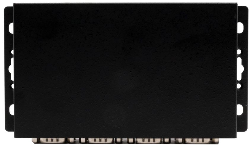
Deutsch                                                                          EX-6118

3. Aufbau, Anschlüsse & LED‘s

  3.1 Aufbau

Vorderseite:

                                                                                 Status LED

                     RXD LED     8x Seriell 9 Pin D-SUB Stecker   TXD LED

Rückseite:

                        5-24V T-Block für optionales   5-24V DC Anschluss für
                             externes Netzteil           beiliegendes Netzteil

Power/ACT LED
PoE LED

Reset Schalter

        RJ45 Anschluss für Daisy-Chain        RJ45 Anschluss      Power LED
       Anschluss einer weiteren EX-61xx
      oder eines anderen Ethernet Gerätes
          (Geschwindigkeit 100Mbps!)

                 © Copyright 2022 by EXSYS Vertriebs GmbH. All Rights Reserved

                                                4
EX-6118                                                                                  Deutsch

3. Aufbau, Anschlüsse & LED‘s

  3.2 Anschlüsse & LED‘s

DB 9M:

                             Seriell 9 Pin D-SUB Stecker
                               Pin        Signal          Pin      Signal         Pin       Signal
                                1          DCD              4       DTR           7         RTS
                                2          RXD              5     GROUND          8         CTS
                                3          TXD              6       DSR           9      (Power)

RJ45 Anschluss:

                             RJ45 Anschluss
                                Pin      Signal       Pin       Signal      Pin    Signal
                                1       BI_DA+        4         BI_DC+      7      BI_DD+
                                2        BI_DA-       5         BI_DC-      8      BI_DD-
                                3       BI_DB+        6         BI_DB-

LED‘s:

         LED Name       Farbe                               LED Funktion
                                    Ständig an: Am RJ45 liegt Strom an
     Power/Act LED
                        Grün        Blinken: Datenübertragung über das Netzwerk
        (RJ45)
                                    Aus: Am RJ45 liegt kein Strom an
                              Ständig an: Entnahme des Stroms aus dem LAN-Kabel
         PoE LED
                       Orange (nur PoE Modell)
          (RJ45)
                              Off: PoE Strom wird nicht entnommen

                                    Ständig an: Das Gerät ist eingeschaltet
         Power LED      Grün
                                    Aus: Das Gerät ist ausgeschaltet

                                    Blinken: Server ist bereit für Endgeräte
         Status LED     Grün
                                    Aus: Server ist nicht bereit

         TXD LED                    Blinken: Die serielle Schnittstelle sendet Daten
                        Grün
          (rechts)                  Aus: Die serielle Schnittstelle sendet keine Daten

         RXD LED                    Blinken: Die serielle Schnittstelle empfängt Daten
                       Orange
          (links)                   Aus: Die serielle Schnittstelle empfängt keine Daten

               © Copyright 2022 by EXSYS Vertriebs GmbH. All Rights Reserved

                                                  5
Deutsch                                                                                EX-6118

4. Hardware Installation
Beachten Sie bitte die folgenden Installationshinweise. Da es große Unterschiede zwischen PC‘s
gibt, können wir Ihnen nur eine generelle Anleitung zum Anschluss der EX-6118 geben. Bei Un-
klarheiten   halten   Sie sich   bitte   an   die   Bedienungsanleitung   Ihres   Computersystems.

1. Installieren Sie die EX-6118 mit dem optional erhältlichem DIN-Rail Kit auf einer Tragschiene
    oder direkt an eine Wand.

                                     Löcher für Wandmontage

2. Nun verwenden Sie ein Ethernet Kabel und verbinden Sie dieses mit dem RJ45 Anschluss der
   EX-6118 und das andere Ende mit einem PC oder einem Switch.
3. Verbinden Sie nun Ihre seriellen Endgeräte mit den 9 Pin D-SUB Stecker der EX-6118.
4. Schließen Sie jetzt das im Lieferumfang enthaltene 12V Netzteil an die dafür vorhergesehene
   12V Buchse der EX-6118 an. Sobald diese LED leuchtet, ist das Gerät betriebsbereit.

                © Copyright 2022 by EXSYS Vertriebs GmbH. All Rights Reserved

                                                    6
EX-6118                                                                           Deutsch

5. Konfiguration des Geräteserver
Der EX-6118 wird mit folgenden Werkseinstellungen ausgeliefert:

                    Login User Name:                              admin

                       Password:                                  system
                       IP Address:                 DHCP (Automatisch zugewiesen)

                Network Operation Mode:                      VCOM Mode
                     Serial Interface:                            RS-232

Falls Sie den EX-6118 auf „Werkseinstellung“ zurücksetzen möchten, dann drücken und halten
Sie den Reset Schalter für ca. 3-5 Sekunden gedrückt.
Bitte beachten Sie das die Einstellungen nach dem Reset nicht identisch sind mit den Werksein-
stellungen! Wenn Sie den EX-6118 auf „Werkseinstellung“ zurückgesetzt haben, werden Sie fol-
gende Einstellungen im Gerät haben:

                    Login User Name:                           admin
                        Password:                             system

                       IP Address:                      Statisch 192.168.2.1

                Network Operation Mode:                  TCP Server Mode

                     Serial Interface:                        RS-232

               © Copyright 2022 by EXSYS Vertriebs GmbH. All Rights Reserved

                                               7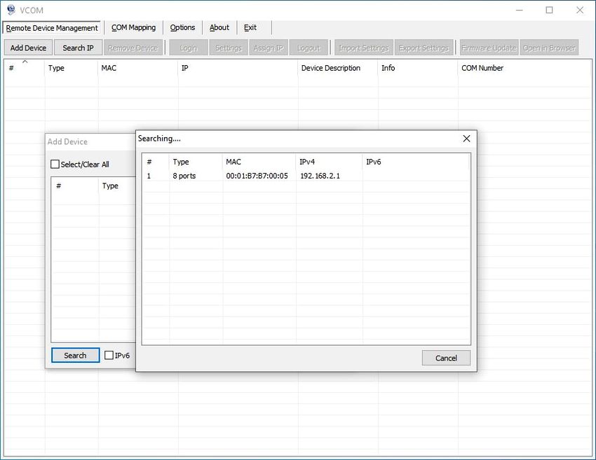
Deutsch                                                                              EX-6118

6. VCOM Admin Utility
Da der EX-6118 mit aktiviertem DHCP-Modus ausgeliefert wurde, ist eine IP-Adresse erforderlich,
um ihn zu konfigurieren. Der EX-6118 erhält standardmäßig automatisch eine IP-Adresse von
einem DHCP-Server (z.B. Ihrem Router). Wenn er nicht mit einem DHCP-Server verbunden ist,
verwenden Sie die Standard-IP-Adresse: 192.168.2.1. Um die IP-Adresse zu ermitteln, müssen
Sie das mitgelieferte VCOM Admin Utility (vspsetup.exe) installieren. Das Installationsprogramm
befindet sich auf der im Lieferumfang enthaltenen Treiber-CD in folgendem Ordner.
Wichtig! Bitte führen Sie das Installationsprogramm mit Rechtsklick „Als Administrator ausführen“
aus!

1. Ermitteln Sie die IP-Adresse: Starten Sie das VCOM Admin Utility (klicken Sie mit Rechtsklick
auf dem Windows-Desktop auf die Verknüpfung VCOM Admin Utility und starten Sie dies mit „Als
Administrator ausführen“).
Klicken Sie auf Remote Device Management > ADD Device > Search
Nachdem der EX-6118 gefunden wurde, klicken Sie auf Cancel, um die Suche abzubrechen.
Klicken Sie auf OK, um den EX-6118 hinzuzufügen.

               © Copyright 2022 by EXSYS Vertriebs GmbH. All Rights Reserved

                                               8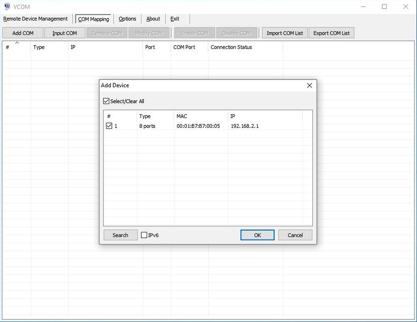
EX-6118                                                                       Deutsch

6. VCOM Admin Utility
2. Zuordnung der COM-Ports: Um den virtuellen COM-Anschluss zu erstellen und dem seriellen
Gerät zuzuordnen, klicken Sie auf COM Mapping > Add COM > OK
Um die COM-Port-Nummer zu ändern, klicken Sie auf COM Mapping > Modify COM

Der COM2-COM9 wurde nun hinzugefügt!

              © Copyright 2022 by EXSYS Vertriebs GmbH. All Rights Reserved

                                            9
Deutsch                                                                            EX-6118

6. VCOM Admin Utility
Überprüfen Sie bitte ob im Gerätemanager die COM-Port‘s hinzugefügt wurden! Es sollte nun
folgender Einträge im Gerätemanager sichtbar sein:

3. Ändern der Einstellungen der seriellen Schnittstelle: Wenn Sie die Einstellungen der seriel-
len Schnittstelle auf andere Werte als die Standardwerte ändern (z.B. Device Description, Pass-
word, ...), müssen Sie sich zuerst am Device Server anmelden (das Standardpasswort hierfür
"system").
Klicken Sie auf Remote Device Management > Login

               © Copyright 2022 by EXSYS Vertriebs GmbH. All Rights Reserved

                                              10
EX-6118 Deutsch
6. VCOM Admin Utility
Nachdem Sie eingeloggt sind, klicken Sie auf Remote Device Management und dann Doppelklick
auf den ausgewählten Device Server in der Liste.
Doppelklick
Klicken Sie auf Remote Device Management > (Doppelklick auf das ausgewählte Element in der
Liste) > Basic > Device Description > OK
Doppelklick
© Copyright 2022 by EXSYS Vertriebs GmbH. All Rights Reserved
11Deutsch EX-6118
6. VCOM Admin Utility
4. Ändern des Port-Betriebsmodus: Wenn Sie den Port-Betriebsmodus auf andere Modi (z.B.
Modbus, UDP, TCP Client, ...) als den Standard-VCOM-Modus ändern, müssen Sie stattdessen
den Webbrowser verwenden. Um das Web-Konfigurationsmenü zu öffnen, klicken Sie auf Remote
Device Management > (wählen Sie "Device Server Item" in der Liste) > Open in Browser und
geben Sie folgende Anmeldedaten ein:
User Name: admin
Password: system
Klicken Sie auf Port Config > Port 1 > Operation Mode > Apply > Save & Reboot
© Copyright 2022 by EXSYS Vertriebs GmbH. All Rights Reserved
12EX-6118 Deutsch
7. Jumper Einstellungen
Die EX-6118 bietet Ihnen die Möglichkeit 5V auf den Pin 9 des seriellen Anschlusses zu leiten.
Hierzu gibt es acht Jumper im inneren auf der Platine der EX-6118. Um an Jumper umzusetzen,
müssen Sie die vier Schrauben auf den Seiten der EX-6118 herausschrauben und das obere Ge-
häuse lösen. Für jeden Port gibt es einen separaten Jumper. In den meisten Fällen müssen Sie an
den Jumper keine Änderungen vornehmen! Die Jumper sind bei Werksauslieferung alle auf „DIS“
(Disable) gesetzt. Die Einstellungen sind für jeden seriellen Port individuell einstellbar. Die Zuwei-
sung welcher Jumper welchen Port steuert, entnehmen Sie bitte dem folgenden Bild. Aus der
nachfolgenden Tabellen können Sie die Einstellung der Jumper entnehmen. Bei Einstellung „ENA“
(Enable), muss ein Netzteil mit dem EX-6118 verbunden sein!
Wichtig! Bitte beachten Sie das Ihr Endgerät auch dies unterstützt! Andernfalls können Beschädi-
gungen an Ihrem Endgerät entstehen!
Jumper JP2 & JP3 Jumper JP4 & JP5 Jumper JP6 & JP7 Jumper JP8 & JP9
für Port 1 & 2 für Port 3 & 4 für Port 5 & 6 für Port 7 & 8
JP2-JP9:
ENA | DIS
DIS = Am Pin 9 liegt das Standard Signal RI (Ring Indicator)
(Werkseinstellung)
ENA = Am Pin 9 liegt jetzt eine Spannung von +5V an
© Copyright 2022 by EXSYS Vertriebs GmbH. All Rights Reserved
13Deutsch EX-6118
8. Reinigung
Zur Reinigung des Gerätes verwenden Sie bitte ausschließlich ein trockenes nicht faserndes Tuch
und entfernen Sie die Verschmutzung mit leichtem Druck. Im Bereich der Anschlüsse bitte darauf
Achten, dass keine Fasern des Tuchs in der Buchse hinterlassen werden. Verwenden Sie bitte
zu Reinigung in keinem Fall ein feuchtes oder nasses Tuch!
9. Technische Daten
Datentransfer-Rate: 50 bis 921.6 Kbps Baud Rate
Anschlüsse: 8x 9 Pin D-SUB serieller Stecker, 2x RJ45 Ethernet Anschluss,
1x 5-24V DC Buchse, 1x Terminal Block 5-24V
Hardwaresystem: Ethernet 10/100 Mbit/s
VCOM Admin Utility: Windows XP/ Vista/ 7/ 8.x/ 10/ Server 20xx
Betriebssystem: Alle über IP und Port Nummer (Direktzugriff Socket Port)
Betriebstemperatur: 0° bis 60° Celsius
Lagertemperatur: -20° bis 75° Celsius
Rel. Luftfeuchtigkeit: 5% bis 95%
Schutzklasse: IP30
Stromversorgung: +5-24V
Abmessung: 173,65 x 93,00 x 44,00 mm
Gewicht: 1120g
10. Technische Zeichnung
© Copyright 2022 by EXSYS Vertriebs GmbH. All Rights Reserved
14EX-6118 English
1. Description
The EX-6118 is a multi-protocol RS-232 serial device server. Which is designed to connect eight
RS-232 serial devices, including POS, barcode readers, sensors, meters, CNC controllers and
PLCs to an IP-based Ethernet network. The serial devices are thus connected to the network and
are thus available for sharing on the Internet, with remote configuration using the extensive net-
work protocols such as TCP server, TCP client, UDP, VCOM, serial Telnet, RFC2217, remote pair
master slave, Modbus RTU. To be backward compatible with the legacy serial device running the
existing COM port application software, EX-6118 provides a virtual COM port redirection driver
(VCOM) that perfectly migrates your serial application without modifying the software. In addition,
serial devices with remote pair master-slave mode can communicate with each other via peer-to-
peer mode without the need for an intermediate PC or conversion software.
Features:
• 8x RS-232 Port via RJ45 Ethernet 10/100Mbps
• Up to 921.6 Kbps Baud Rate
• Network Protocols: TCP Server, TCP Client, UDP, VCOM, Serial Telnet, RFC2217, Remote-
Pair-Master-Slave, Modbus Server, Modbus Client and SNMP
• Configuration: Windows-based VCOM-Administrator-Utility and Web-Browser
• Support 15KV ESD-Protection for all serial Signals
• Support 5V on Pin 9 of the serial port
• Certificate for
2. Extent of Delivery
Before you integrate the EX-6118 into your network, you should first check the contents of the
delivery:
• EX-6118
• Power Supply (12V/3A)
• Manual
• Driver CD
© Copyright 2022 by EXSYS Vertriebs GmbH. All Rights Reserved
15English EX-6118
3. Layout, Connections & LED’s
3.1 Layout
Front:
Status LED
RXD LED 8x Seriell 9 Pin D-SUB Connector TXD LED
Back:
5-24V T-Block for optional 5-24V DC Connector for
Power Supply included Power Supply
Power/ACT LED
PoE LED
Reset Button
RJ45 connector for daisy-chain RJ45 Port Power LED
connection of another EX-61xx or
another Ethernet device
(Speed 100Mbps!)
© Copyright 2022 by EXSYS Vertriebs GmbH. All Rights Reserved
16EX-6118 English
3. Layout, Connections & LED’s
3.2 Connections & LED‘s
DB 9M:
Serial 9 Pin D-SUB Connector
Pin Signal Pin Signal Pin Signal
1 DCD 4 DTR 7 RTS
2 RXD 5 GROUND 8 CTS
3 TXD 6 DSR 9 (Power)
RJ45 Port:
RJ45 Port
Pin Signal Pin Signal Pin Signal
1 BI_DA+ 4 BI_DC+ 7 BI_DD+
2 BI_DA- 5 BI_DC- 8 BI_DD-
3 BI_DB+ 6 BI_DB-
LED‘s:
LED Name Color LED Function
Steady on: Power is On
Power/Act LED
Green Blinking: Transferring data on the Network
(RJ45)
Off: Power is Off
PoE LED Steady on: Extracting the power from LAN cable (PoE model only)
Orange
(RJ45) Off: LAN cable PoE Power is not extracted
Steady on: The unit has booted
Power LED Green
Off: The unit is not booted yet
Blinking: Server is ready for end devices
Status LED Green
Off: Server is not ready
TXD LED Blinking: The Serial Port is sending out data
Green
(right) Off: The Serial Port is not sending out any data
RXD LED Blinking: The Serial Port is receiving data
Orange
(left) Off: The Serial Port is not receiving any data
© Copyright 2022 by EXSYS Vertriebs GmbH. All Rights Reserved
17English EX-6118
4. Hardware Installation
Please observe the following installation instructions. Because there are big differences between
PC's, we can only give you a general guide for connecting the EX-6118. If you have any questions,
please refer to the operating instructions of your computer system.
1. Install the EX-6118 on a mounting rail by using the optional DIN rail kit or on a wall.
Holes for Wall Installation
2. Now use an Ethernet cable and connect it to the RJ45 port of the EX-6118 and the other end to a
PC or a switch.
3. Now connect your serial devices to the 9 pin D-SUB connectors of the EX-6118.
4. Now connect the 12V power supply which is included in the extend of delivery to the 12V socket
provided for this purpose on the EX-6118. As soon as this LED is steady on, the device is ready
for operation.
© Copyright 2022 by EXSYS Vertriebs GmbH. All Rights Reserved
18EX-6118 English
5. Configuration of the Device Server
The EX-6118 is delivered with the following factory settings:
Login User Name: admin
Password: system
IP Address: DHCP (Assigned Automatically)
Network Operation Mode: VCOM Mode
Serial Interface: RS-232
If you want to reset the EX-6118 to "Factory Settings", then press and hold the reset button for
approx. 3-5 seconds.
Please note that the settings after the reset are not identical to the factory settings! When you have
reset the EX-6118 to "Factory Settings", you will have the following settings in the device:
Login User Name: admin
Password: system
IP Address: Static 192.168.2.1
Network Operation Mode: TCP Server Mode
Serial Interface: RS-232
© Copyright 2022 by EXSYS Vertriebs GmbH. All Rights Reserved
19English EX-6118
6. VCOM Admin Utility
Since the EX-6118 was shipped with DHCP mode enabled, an IP address is required to configure
it. By default, the EX-6118 automatically receives an IP address from a DHCP server (e.g. your
router). If it is not connected to a DHCP server, use the default IP address: 192.168.2.1. To deter-
mine the IP address, you must install the VCOM Admin Utility (vspsetup.exe) that comes with the
device. The installation program is located on the driver CD included in the scope of delivery in the
following folder.
Attention! Please run the installation program with right click "Run as administrator!
1. Get the IP address: Start the VCOM Admin Utility (right-click on the VCOM Admin Utility
shortcut on the Windows desktop and start this with „Run as Administrator“).
Click Remote Device Management > ADD Device > Search
After the EX-6118 was found, click Cancel to abort the search. Click OK, to add the EX-6118.
© Copyright 2022 by EXSYS Vertriebs GmbH. All Rights Reserved
20EX-6118 English
6. VCOM Admin Utility
2. Assignment of COM-Ports: To create the virtual COM-Port and assign it to the serial device,
click COM Mapping > Add COM > OK
To change the COM-Port number, click COM Mapping > Modify COM
The COM2-COM9 has now been added!
© Copyright 2022 by EXSYS Vertriebs GmbH. All Rights Reserved
21English EX-6118
6. VCOM Admin Utility
Please check if the COM-Port has been added in the device manager! The following entry should
now be visible in the device manager:
3. Changing the settings of the serial interface: If you change the settings of the serial interface
to values other than the default values (e.g. Device Description, Password, ...), you must first log in
to the Device Server (the default password for this is "system").
Click Remote Device Management > Login
© Copyright 2022 by EXSYS Vertriebs GmbH. All Rights Reserved
22EX-6118 English
6. VCOM Admin Utility
After you are logged in, click Remote Device Management and then double-click the selected
device server in the list.
double click
Click Remote Device Management > (double-click on the selected element in the list) > Basic >
Device Description > OK
double click
© Copyright 2022 by EXSYS Vertriebs GmbH. All Rights Reserved
23English EX-6118
6. VCOM Admin Utility
4. Changing Port Operation Mode: If you change the port operation mode to other modes (e.g.
Modbus, UDP, TCP Client, ...) than the default VCOM mode, you must use the web browser in-
stead. To open the web configuration menu, click Remote Device Management > (select "Device
Server Item") > Open in Browser and enter following credentials:
User Name: admin
Password: system
Click Port Config > Port 1 > Operation Mode > Apply > Save & Reboot
© Copyright 2022 by EXSYS Vertriebs GmbH. All Rights Reserved
24EX-6118 English
7. Jumper Settings
The EX-6118 offers you the possibility to connect 5V to Pin 9 of the serial port. For this purpose
there are eight jumpers inside on the board of the EX-6118. To change jumpers you have to un-
screw the four screws on the sides of the EX-6118 and loosen the upper housing. There is a sepa-
rate jumper for each port. In most cases you do not have to make any changes to the jumpers!
The jumpers are all set to "DIS" (Disable) when shipped from the factory. The settings can be
adjusted individually for each serial port. The assignment of which jumper controls which port can
be seen in the following picture. From the following tables you can see the setting of the jumpers.
With setting "ENA" (Enable), a power supply must be connected to EX-6118!
Important! Please make sure that your end device also supports this! Otherwise, damage to your
terminal device may occur!
Jumper JP2 & JP3 Jumper JP4 & JP5 Jumper JP6 & JP7 Jumper JP8 & JP9
for Port 1 & 2 for Port 3 & 4 for Port 5 & 6 for Port 7 & 8
JP2-JP9:
ENA | DIS
DIS = Pin 9 is the standard signal RI (Ring Indicator)
(Factory Setting)
ENA = A voltage of +5V is now present at Pin 9
© Copyright 2022 by EXSYS Vertriebs GmbH. All Rights Reserved
25English EX-6118
8. Cleaning
For cleaning please use only a dry fluff less cloth and remove the dirt with gently pressure. In the
area of the connectors please make sure that no fibres from the cloth remain in the connectors.
Attention! Never use a moist or wet cloth for cleaning!
9. Technical Information
Data Transfer Rate: 50 to 921.6 Kbps Baud Rate
Connectors: 8x 9 Pin D-SUB serial Connector, 2x RJ45 Ethernet Port,
1x 5-24V DC Connector, 1x Terminal Block 5-24V
Hardware System: Ethernet 10/100 Mbit/s
VCOM Admin Utility: Windows XP/ Vista/ 7/ 8.x/ 10/ Server 20xx
Operating System: All via IP and Port Number (Direct Control Socket Port)
Operating Temperature: 32° to 140° Fahrenheit
Storage Temperature: -4° to 167° Fahrenheit
Rel. Humidity: 5% to 95%
Protection Class: IP30
Power: +5-24V
Size: 173,65 x 93,00 x 44,00 mm
Weight: 1120g
10. Technical Drawing
© Copyright 2022 by EXSYS Vertriebs GmbH. All Rights Reserved
26Sie können auch lesen