Installations- und Bedienungsanleitung Installation and operating manual
←
→
Transkription von Seiteninhalten
Wenn Ihr Browser die Seite nicht korrekt rendert, bitte, lesen Sie den Inhalt der Seite unten
Installations- und
Bedienungsanleitung
Installation and operating manual

Jalousieaktor für Hutschienen-      S. 2
montage – 4-fach
Blind Actuator for DIN rail mount   P. 36
– 4 channels

HmIP-DRBLI4
Lieferumfang
Anzahl     Bezeichnung
1          Homematic IP Jalousieaktor für
           Hutschienenmontage – 4-fach
1          Bedienungsanleitung

Dokumentation © 2019 eQ-3 AG, Deutschland
Alle Rechte vorbehalten. Ohne schriftliche Zustimmung des
Herausgebers darf diese Anleitung auch nicht auszugsweise in
irgendeiner Form reproduziert werden oder unter Verwendung
elektronischer, mechanischer oder chemischer Verfahren verviel-
fältigt oder verarbeitet werden.
Es ist möglich, dass die vorliegende Anleitung noch drucktech-
nische Mängel oder Druckfehler aufweist. Die Angaben in dieser
Anleitung werden jedoch regelmäßig überprüft und Korrekturen
in der nächsten Ausgabe vorgenommen. Für Fehler technischer
oder drucktechnischer Art und ihre Folgen übernehmen wir keine
Haftung.
Alle Warenzeichen und Schutzrechte werden anerkannt.
Printed in Hong Kong
Änderungen im Sinne des technischen Fortschritts können ohne
Vorankündigung vorgenommen werden.

154370 (web)
Version 1.1 (05/2020)
1
B
A
C
D
E
F
G
L H
K
J G
I
F
E2
OFF
3
1
24 5
6

    Anschluss des Motors (Ausgänge)
    Motor connection (outputs)
7
Anschluss von Tastern/Schaltern (Eingänge) und
Versorgungsspannung
Connection of push-buttons/switches (inputs) and
supply voltage8
ON
9
HAP
Homematic IP10 11
12

13

     4s
14
4s
Inhaltsverzeichnis
1    Hinweise zur Anleitung.................................................. 13
2    Gefahrenhinweise........................................................... 13
3    Funktion und Geräteübersicht.....................................18
4    Allgemeine Systeminformationen.............................. 20
5    Inbetriebnahme.............................................................. 20
     5.1     Installationshinweise........................................................... 20
     5.2     Montage und Installation................................................... 22
     5.3     Anlernen................................................................................ 25
6    Bedienung.........................................................................27
7    Fehlerbehebung............................................................. 30
     7.1		   Fehlercodes und Blinkfolgen............................................ 30
     7.2     Befehl nicht bestätigt...........................................................31
     7.3     Duty Cycle .............................................................................31
8    Wiederherstellung der Werkseinstellungen...............32
9    Wartung und Reinigung.................................................33
10   Allgemeine Hinweise zum Funkbetrieb......................33
11   Technische Daten...........................................................34

12
Hinweise zur Anleitung
1 Hinweise zur Anleitung
Lesen Sie diese Anleitung sorgfältig, bevor Sie Ihr Home-
matic IP Gerät in Betrieb nehmen. Bewahren Sie die An-
leitung zum späteren Nachschlagen auf!
Wenn Sie das Gerät anderen Personen zur Nutzung über-
lassen, übergeben Sie auch diese Anleitung.
Benutzte Symbole:
Achtung!
Hier wird auf eine Gefahr hingewiesen.
Hinweis. Dieser Abschnitt enthält zusätzliche
wichtige Informationen.
2 Gefahrenhinweise
Öffnen Sie das Gerät nicht. Es enthält keine durch
den Anwender zu wartenden Teile. Das Öffnen
birgt die Gefahr eines Stromschlages. Lassen Sie
das Gerät im Fehlerfall von einer Fachkraft prüfen.
Aus Sicherheits- und Zulassungsgründen (CE) ist
das eigenmächtige Umbauen und/oder Verän-
dern des Geräts nicht gestattet.
13Gefahrenhinweise
Verwenden Sie das Gerät nicht, wenn es von au-
ßen erkennbare Schäden, z. B. am Gehäuse, an
Bedienelementen oder an den Anschlussbuchsen
ausweist. Lassen Sie das Gerät im Zweifelsfall von
einer Fachkraft prüfen.
Betreiben Sie das Gerät nur in trockener sowie
staubfreier Umgebung, setzen Sie es keinem Ein-
fluss von Feuchtigkeit, Vibrationen, ständiger
Sonnen- oder anderer Wärmeeinstrahlung, Kälte
und keinen mechanischen Belastungen aus.
Das Gerät ist kein Spielzeug! Erlauben Sie Kindern
nicht damit zu spielen. Lassen Sie das Verpa-
ckungsmaterial nicht achtlos liegen. Plastikfolien/
-tüten, Styroporteile etc. können für Kinder zu
einem gefährlichen Spielzeug werden.
Bei Sach- oder Personenschäden, die durch un-
sachgemäße Handhabung oder Nichtbeachten
der Gefahrenhinweise verursacht werden, über-
nehmen wir keine Haftung. In solchen Fällen er-
lischt jeder Gewährleistungsanspruch! Für Folge-
schäden übernehmen wir keine Haftung!
14Gefahrenhinweise
Der Aktor ist Teil der Gebäudeinstallation. Bei der
Planung und Errichtung sind die einschlägigen
Normen und Richtlinien des Landes zu beachten.
Der Betrieb des Geräts ist ausschließlich am
230 V/50 Hz-Wechselspannungsnetz zulässig.
Arbeiten am 230-V-Netz dürfen nur von einer
Elektrofachkraft (nach VDE 0100) erfolgen. Dabei
sind die geltenden Unfallverhütungsvorschriften
zu beachten. Zur Vermeidung eines elektrischen
Schlages am Gerät, schalten Sie bitte die Netz-
spannung frei (Sicherungsautomat abschalten).
Bei Nichtbeachtung der Installationshinweise
können Brand oder andere Gefahren entstehen.
An die Anschlussklemmen der Ein- und Ausgänge,
inkl. der Nebenstelleneingänge, dürfen keine
SELV-/PELV-Stromkreise angeschlossen werden.
Beachten Sie beim Anschluss an die
Geräteklemmen die hierfür zulässigen Leitungen
und Leitungsquerschnitte.
Die angeschlossenen Verbraucher müssen über
eine ausreichende Isolierung verfügen.
Eine Überlastung kann zur Zerstörung des Geräts,
zu einem Brand oder zu einem elektrischen
Schlag führen.
15Gefahrenhinweise
Beachten Sie vor Anschluss eines Verbrauchers die
technischen Daten, insbesondere die maximal
zulässige Schaltleistung der Lastkreise und Art des
anzuschließenden Verbrauchers. Belasten Sie den
Aktor nur bis zur angegebenen Leistungsgrenze.
Die Laststromkreise müssen mit einem Leitungs-
schutzschalter gemäß EN60898-1 (Auslösecha-
rakteristik B oder C, max. 10 A Nennstrom, min. 6
kA Abschaltvermögen, Energiebegrenzungsklas-
se 3) abgesichert sein.
Für den sicheren Betrieb muss das Gerät in einen
Stromkreisverteiler entsprechend VDE 0603, DIN
43871 (Niederspannungsunterverteilung (NSUV)),
DIN 18015-x eingebaut werden. Die Montage muss
auf einer Tragschiene (Hutschiene, DIN-Rail) lt.
EN 60715 erfolgen. Installation und Verdrahtung
sind entsprechend VDE 0100 (VDE 0100-410, VDE
0100-510 usw.) durchzuführen. Es sind die Vor-
schriften der Technischen Anschlussbestimmungen
(TAB) des Energieversorgers zu berücksichtigen.
Vor Einbau und Anschluss des Geräts freischalten
und spannungsführende Teile in der Umgebung
abdecken.
Das Gerät ist nicht zum Freischalten geeignet.
16Gefahrenhinweise
Verwenden Sie nur Jalousien bzw. Rollläden mit
Endlagenschalter (mechanisch oder elektro-
nisch). Prüfen Sie die Endlagenschalter der ange-
schlossenen Motoren vor der Inbetriebnahme
des Aktors auf korrekte Justierung.
Schließen Sie keine Drehstrommotoren an.
Bei Einsatz in einer Sicherheitsanwendung ist das
Gerät/System in Verbindung mit einer USV (un-
terbrechungsfreie Stromversorgung) zu betrei-
ben, um einen möglichen Netzausfall zu über-
brücken.
Das Gerät ist nur für den Einsatz in Wohnberei-
chen, Geschäfts- und Gewerbebereichen sowie
in Kleinbetrieben bestimmt.
Jeder andere Einsatz, als der in dieser Bedie-
nungsanleitung beschriebene, ist nicht bestim-
mungsgemäß und führt zu Gewährleistungs- und
Haftungsausschluss.
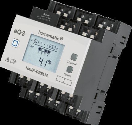
17Funktion und Geräteübersicht 3 Funktion und Geräteübersicht Der Homematic IP Jalousieaktor – 4-fach lässt sich ein- fach auf einer Hutschiene in einem Stromkreisverteiler montieren. Einmal installiert, steuert er angeschlossene Jalousien, Rollläden oder Markisen über vier potential- freie, unabhängige Kanäle. Der Jalousieaktor ermöglicht eine komfortable Steuerung angeschlossener Jalousie-, Rollladen- bzw. Markisenan- triebe über angelernte Taster, Funk-Fernbedienungen oder über die kostenlose Homematic IP Smartphone- App. Über angeschlossene konventionelle Taster oder Schalter ist zudem eine direkte Bedienung möglich. Geräteübersicht (s. Abbildung 1): A Systemtaste (Anlerntaste und LED) B Channel-Taste C Select-Taste D LC-Display E Anschlussklemmen für geschalteten Außenleiter zum Steuern des Motors („Runter“) F Anschlussklemmen für geschalteten Außenleiter zum Steuern des Motors („Hoch“) G Anschlussklemmen für Außenleiter H Anschlussklemme für Taster/Schalter Kanal 2, 4, 6, 8 („Hoch“) I Verrastung für die Hutschienenmontage J Anschlussklemme Außenleiter (Geräteversorgung) K Anschlussklemme Neutralleiter L Anschlussklemme für Taster/Schalter Kanal 1, 3, 5, 7 („Runter“) 18
Funktion und Geräteübersicht

    Displayübersicht (s. Abbildung 1):
      Symbol         Bedeutung
                     Kanal eingeschaltet
   1 1

                     Kanal ausgeschaltet
   RX 1 1

 1 TX111RX 11             V
                     Eingang nicht betätigt

                              V
       1    1        Eingang betätigt
       TX
     RX
 1 11RX1
                     Daten werden empfangen
1 1
     TX
     TX
        1        1
                                     V
                                     V
                     Daten werden gesendet

RX RX       RX       Höhe der Jalousie bzw. des Rollladens am
RX                   ausgewählten Kanal

                            VV V
TX TX       TX                 V
                     Lamellenposition der Jalousie am
TX                   ausgewählten Kanal
                     Prozentangabe (eingeschaltet, wenn die
                     Höhe, Lamellenposition oder Duty-Cycle
      V              angezeigt wird)
                     Temperaturangabe (eingeschaltet, wenn
                     Temperatur angezeigt wird)
  V
                                                                 19
Allgemeine Systeminformationen
4 Allgemeine Systeminformationen
Dieses Gerät ist Teil des Homematic IP Smart-Home-
Systems und kommuniziert über das Homematic IP
Funkprotokoll. Alle Geräte des Systems können komfor-
tabel und individuell per Smartphone über die Home-
matic IP App konfiguriert werden. Alternativ haben Sie
die Möglichkeit, Homematic IP Geräte über die Zent-
rale CCU2/CCU3 oder in Verbindung mit vielen Part-
nerlösungen zu betreiben. Welcher Funktionsumfang
sich innerhalb des Systems im Zusammenspiel mit wei-
teren Komponenten ergibt, entnehmen Sie bitte dem
Homematic IP Anwenderhandbuch. Alle technischen
Dokumente und Updates finden Sie stets aktuell unter
www.homematic-ip.com.
5 Inbetriebnahme
5.1 Installationshinweise
Bitte notieren Sie sich vor der Installation die auf
dem Gerät angebrachte Gerätenummer (SGTIN)
und den Verwendungszweck, damit Sie das Gerät
im Nachhinein leichter zuordnen können. Alter-
nativ steht die Gerätenummer auch auf dem bei-
liegenden QR-Code-Aufkleber.
Hinweis! Installation nur durch Personen mit
einschlägigen elektrotechnischen Kenntnissen
und Erfahrungen!*
20Inbetriebnahme
Durch eine unsachgemäße Installation gefährden Sie
• Ihr eigenes Leben;
• das Leben der Nutzer der elektrischen Anlage.
Mit einer unsachgemäßen Installation riskieren Sie
schwere Sachschäden, z. B. durch Brand. Es droht für Sie
die persönliche Haftung bei Personen- und Sachschäden.
Wenden Sie sich an einen Elektroinstallateur!
*Erforderliche Fachkenntnisse für die Installation:
Für die Installation sind insbesondere folgende Fachkenntnisse er-
forderlich:
• Die anzuwendenden „5 Sicherheitsregeln“:
Freischalten; gegen Wiedereinschalten sichern;
Spannungsfreiheit feststellen; Erden und Kurzschließen;
benachbarte, unter Spannung stehende Teile abdecken
oder abschranken;
• Auswahl des geeigneten Werkzeuges, der Messgeräte
und ggf. der persönlichen Schutzausrüstung;
• Auswertung der Messergebnisse;
• Auswahl des Elektro-Installationsmaterials zur Sicherstel-
lung der Abschaltbedingungen;
• IP-Schutzarten;
• Einbau des Elektroinstallationsmaterials;
• Art des Versorgungsnetzes (TN-System, IT-System,
TT-System) und die daraus folgenden Anschlussbedin-
gungen (klassische Nullung, Schutzerdung, erforderliche
Zusatzmaßnahmen etc.).
Beachten Sie bei der Installation die Gefahrenhin-
weise gemäß „2 Gefahrenhinweise“ auf Seite 13.
21Inbetriebnahme
Beachten Sie die auf dem Gerät angegebene Ab-
isolierlänge der anzuschließenden Leiter.
Zugelassene Leitungsquerschnitte zum Anschluss an den
Jalousieaktor sind:
Starre Leitung [mm2] Flexible Leitung ohne
Aderendhülse [mm2]
0,75 – 2,50 0,75 – 2,50
5.2 Montage und Installation
Bitte lesen Sie diesen Abschnitt erst vollständig,
bevor Sie mit der Installation beginnen.
Für die Installation des Jalousieaktors auf einer Hutschiene
im Stromkreisverteiler gehen Sie wie folgt vor:
• Schalten Sie den Stromkreisverteiler frei (s. Ab-
bildung 2) und decken ggf. spannungsführende
Teile ab (s. Sicherheitsregeln).
• Entfernen Sie die Abdeckung des Stromkreisver-
teilers.
• Setzen Sie den Jalousieaktor auf die Hutschiene
auf (s. Abbildung 3). Achten Sie darauf, dass die
Schrift auf dem Gerät und im Display für Sie les-
bar ist und die Anschlussklemmen der Kanäle 1
und 2 oben liegen.
• Achten Sie darauf, dass die Rastfeder (I) komplett
einrastet und das Gerät fest auf der Schiene sitzt
22Inbetriebnahme
(s. Abbildung 4).
• Verdrahten Sie das Gerät gemäß den Anschluss-
zeichnungen in Abbildung 6 oder 7.
• Schließen Sie zur Versorgung des Jalousieaktors
den Neutralleiter an die Klemme K und den Au-
ßenleiter an die Klemme J an (s. Abbildung 7). Es
können beliebige Außenleiter (L1, L2, L3) ange-
schlossen werden.
• Schließen Sie den Außenleiter für den gewünsch-
ten Kanal an die entsprechende Klemme (G) an
(s. Abbildung 6). An den Netzeingangsklemmen
können beliebige Außenleiter (L1, L2, L3) ange-
schlossen werden.
• Schließen Sie den geschalteten Außenleiter zum
Hochfahren der Jalousien für den gewünschten
Kanal an die entsprechende Klemme ( ) (F) an (s.
Abbildung 6+7).
• Schließen Sie den geschalteten Außenleiter zum
Runterfahren der Jalousien für den gewünschten
Kanal an die entsprechende Klemme ( ) (E) an (s.
Abbildung 6+7).
Der Anschluss für den Außenleiter ist mit einem
Pfeil in Richtung Gerätemitte und die geschalte-
ten Phasen mit einem Pfeil nach außen gekenn-
zeichnet. Zum Anschließen und auch zum Lösen
der Leiter ist der weiße Betätigungshebel oben
auf den Klemmen zu drücken.
23Inbetriebnahme
Die Netzklemmen dürfen nur zum Anschluss der
Netzspannung an das Gerät bzw. zum Anschluss
von Verbrauchern an das Gerät verwendet wer-
den. Das Weiterverbinden (Durchschleifen) von
Leitern über die Netzklemmen des Geräts zu an-
deren Geräten ist nicht erlaubt!
• Schließen Sie die externen Taster/Schalter wie
folgt an die Anschlussklemme 1 bis 8 an (s.
Abbildung 7):
- Anschlussklemme 1, 3, 5, 7 (E): „Runter“
- Anschlussklemme 2, 4, 6, 8 (F): „Hoch“
• Setzen Sie die Abdeckung des Stromkreisvertei-
lers wieder auf.
• Schalten Sie die Haussicherung wieder ein (s. Ab-
bildung 8), um den Anlernmodus des Geräts zu
aktivieren (s. „5.3 Anlernen“ auf Seite 25).
Nach der Installation und vor dem Anlernen des
Geräts an die App, stehen Ihnen bereits einfache
Bedienfunktionen (z. B. für Testzwecke) direkt am
Gerät zur Verfügung (s. „6 Bedienung“ auf Seite
27).
24Inbetriebnahme
5.3 Anlernen
Bitte lesen Sie diesen Abschnitt erst vollständig,
bevor Sie mit dem Anlernen beginnen.
Richten Sie zunächst Ihren Homematic IP Access
Point über die Homematic IP App ein, um weitere
Homematic IP Geräte im System nutzen zu kön-
nen. Ausführliche Informationen dazu finden Sie
in der Bedienungsanleitung des Access Points.
Sie können das Gerät an den Access Point oder an
die Zentrale CCU2/CCU3 anlernen. Weitere Infor-
mationen dazu entnehmen Sie bitte dem Home-
matic IP Anwenderhandbuch (zu finden im Down-
loadbereich unter www.homematic-ip.com).
Damit das Gerät in Ihr System integriert und per kosten-
loser Homematic IP App gesteuert werden kann, muss es
an den Homematic IP Access Point angelernt werden.
Zum Anlernen des Geräts gehen Sie wie folgt vor:
• Öffnen Sie die Homematic IP App auf Ihrem
Smartphone.
• Wählen Sie den Menüpunkt „Gerät anlernen“ aus.
• Nach dem Einschalten der Haussicherung ist der
Anlernmodus des Aktors für 3 Minuten aktiv.
25Inbetriebnahme
Sie können den Anlernmodus manuell für weitere
3 Minuten starten, indem Sie die Systemtaste (A)
kurz drücken (s. Abbildung 9).
• Das Gerät erscheint automatisch in der Home-
matic IP App.
• Zur Bestätigung geben Sie in der App die letzten
vier Ziffern der Gerätenummer (SGTIN) ein oder
scannen Sie den QR-Code. Die Gerätenummer
finden Sie auf dem Aufkleber im Lieferumfang
oder direkt am Gerät.
• Warten Sie, bis der Anlernvorgang abgeschlossen
ist.
• Zur Bestätigung eines erfolgreichen Anlernvor-
gangs leuchtet die LED (A) grün. Das Gerät ist nun
einsatzbereit.
• Leuchtet die LED rot, versuchen Sie es erneut.
• Wählen Sie die gewünschte Lösung für Ihr Gerät
aus.
• Vergeben Sie in der App einen Namen für das Ge-
rät und ordnen Sie es einem Raum zu.
26Bedienung
6 Bedienung
Über die folgenden Tasten stehen Ihnen einfache Bedien-
funktionen direkt am Gerät zur Verfügung:
• Systemtaste (A)
• Channel-Taste (B)
• Select-Taste (C)
• externe Taster/Schalter (H und L)
Systemtaste
Durch kurzes Drücken der Systemtaste (s. Abbildung 10)
können Sie die LCD-Hintergrundbeleuchtung aktivieren.
Channel-Taste
Durch kurzes Drücken der Channel-Taste (s. Abbildung
11) können Sie den gewünschten Kanal auswählen. Bei
jeder Betätigung wird ein Kanal weiter
1 1 geschaltet.
1 1
Der ausgewählte Kanal wird durch Blinken des Symbols
gekennzeichnet.RXDie aktuelle HöheRX ( ) und die aktuelle
V TX
TX ( ) des ausgewählten
Lamellenstellung V werden
Kanals
abwechselnd im LC-Display angezeigt.
Nach Einschalten des Jalousieaktors befinden
sich die Jalousien/Rollläden/Markisen in einer
unbekannten Position, so dass die aktuelle Höhe
und Lamellenstellung eines Kanals bis zum Errei-
chen eines Endschalters nicht angezeigt werden
können. Während dieses Zeitraums wird die aktu-
elle Fahrtrichtung auf dem LC-Display angezeigt:
27Bedienung
Symbol Bedeutung
Runterfahren
Hochfahren
Stopp
Select-Taste
Wenn Sie über die Channel-Taste einen Kanal ausge-
wählt haben (s. Channel-Taste), können Sie durch kurzes
Drücken der Select-Taste (s. Abbildung 12) den Zustand
des Ausgangskanals (Runterfahren - Stopp - Hochfahren
- Stopp usw.) auswählen. Bei jeder Betätigung wird ein
Zustand weiter geschaltet. Bei den Eingangskanälen wird
durch Drücken der Select-Taste ein kurzer Tastendruck
für den ausgewählten Eingang simuliert. Die verknüpften
Aktoren können so geschaltet werden. Diese Funktion
steht nicht zur Verfügung, wenn der Eingang für Schalt-
kontakte konfiguriert ist.
Wenn Sie keinen Kanal ausgewählt haben, können Sie
durch kurzes Drücken der Select-Taste die folgenden An-
zeigen im LC-Display auswählen:
• Duty-Cycle des Jalousieaktors (in %)
• Temperatur im Jalousieaktor (in °C)
• Leere Anzeige
28Bedienung
Externe Taster/Schalter
Mit den externen Tastern/Schaltern kann jeder Kanal di-
rekt rauf- bzw. runterfahren werden.
Taster:
• Kurzer Tastendruck Taste für Kanal 1, 3, 5, 7: Der
Motor für die Rollläden oder die Markise fährt bis
zur Endposition runter.
• Kurzer Tastendruck Taste für Kanal 2, 4, 6, 8: Der
Motor für die Rollläden oder die Markise fährt bis
zur Endposition rauf.
• Kurzer Tastendruck entgegengesetzte Richtung:
Der Motor stoppt.
• Langer Tastendruck: Der Motor fährt so lange
in die entsprechende Richtung, bis Sie die Taste
wieder loslassen oder die Endposition der Rolllä-
den oder Markise erreicht ist.
Schalter:
• Umlegen des Schalters für Kanal 1, 3, 5, 7: Der
Motor für die Rollläden oder die Markise fährt bis
zur Endposition runter.
• Umlegen des Schalters für Kanal 2, 4, 6, 8: Der
Motor für die Rollläden oder die Markise fährt bis
zur Endposition rauf.
• Umlegen des Schalters für die entgegengesetzte
Richtung: Der Motor stoppt.
29Fehlerbehebung
7 Fehlerbehebung
7.1 Fehlercodes und Blinkfolgen
Blinkcode/ Bedeutung Lösung
LCD-Anzeige
Kurzes oranges Anlernmodus Geben Sie die
Blinken (alle aktiv letzten vier Ziffern
10 s) der Geräte-
Seriennummer zur
Bestätigung ein (s.
„5.3 Anlernen“ auf
Seite 25).
6x langes rotes Gerät defekt Achten Sie auf die
Blinken Anzeige in Ihrer
App oder wenden
Sie sich an Ihren
Fachhändler.
1x oranges Testanzeige Nachdem die
und 1x grünes Testanzeige
Leuchten erloschen ist,
können Sie
fortfahren.
E10 Temperatur zu Reduzieren Sie die
hoch angeschlossene Last
und lassen Sie das
Gerät abkühlen.
30Fehlerbehebung
7.2 Befehl nicht bestätigt
Bestätigt mindestens ein Empfänger einen Befehl nicht,
leuchtet zum Abschluss der fehlerhaften Übertragung
die LED (A) rot auf. Grund für die fehlerhafte Übertragung
kann eine Funkstörung sein (s. „10 Allgemeine Hinweise
zum Funkbetrieb“ auf Seite 33). Die fehlerhafte Über-
tragung kann folgende Ursachen haben:
• Empfänger nicht erreichbar,
• Empfänger kann Befehl nicht ausführen (Lastaus-
fall, mechanische Blockade etc.) oder
• Empfänger defekt.
7.3 Duty Cycle
Der Duty Cycle beschreibt eine gesetzlich geregelte Be-
grenzung der Sendezeit von Geräten im 868 MHz-Be-
reich. Das Ziel dieser Regelung ist es, die Funktion aller im
868 MHz-Bereich arbeitenden Geräte zu gewährleisten.
In dem von uns genutzten Frequenzbereich 868 MHz be-
trägt die maximale Sendezeit eines jeden Geräts 1 % einer
Stunde (also 36 Sekunden in einer Stunde). Die Geräte
dürfen bei Erreichen des 1 %-Limits nicht mehr senden,
bis diese zeitliche Begrenzung vorüber ist. Gemäß dieser
Richtlinie, werden Homematic IP Geräte zu 100 % nor-
menkonform entwickelt und produziert.
Im normalen Betrieb wird der Duty Cycle in der Regel
nicht erreicht. Dies kann jedoch in Einzelfällen bei der In-
betriebnahme oder Erstinstallation eines Systems durch
vermehrte und funkintensive Anlernprozesse der Fall sein.
31Wiederherstellung der Werkseinstellungen
Eine Überschreitung des Duty Cycle-Limits wird durch
ein langes rotes Leuchten der LED (A) angezeigt und
kann sich durch temporär fehlende Funktion des Geräts
äußern. Nach kurzer Zeit (max. 1 Stunde) ist die Funktion
des Geräts wiederhergestellt.
8 Wiederherstellung der
Werkseinstellungen
Die Werkseinstellungen des Geräts können wie-
derhergestellt werden. Dabei gehen alle Einstel-
lungen verloren.
Um die Werkseinstellungen des Geräts wiederherzustel-
len, gehen Sie wie folgt vor:
• Drücken Sie für 4 s auf die Systemtaste (A), bis
die LED (A) schnell orange zu blinken beginnt (s.
Abbildung 13).
• Lassen Sie die Systemtaste wieder los.
• Drücken Sie die Systemtaste erneut für 4 s, bis die
LED grün aufleuchtet (s. Abbildung 14).
• Lassen Sie die Systemtaste wieder los, um das
Wiederherstellen der Werkseinstellungen abzu-
schließen.
Das Gerät führt einen Neustart durch.
32Wartung und Reinigung
9 Wartung und Reinigung
Das Gerät ist wartungsfrei. Überlassen Sie eine War-
tung oder Reparatur einer Fachkraft.
Schalten Sie vor Ausbau des Geräts unbedingt die
Netzspannung frei (Sicherungsautomat abschal-
ten)! Arbeiten am 230 V-Netz dürfen nur von ei-
ner Elektro-Fachkraft (nach VDE 0100) erfolgen.
Reinigen Sie das Gerät mit einem weichen, sauberen, tro-
ckenen und fusselfreien Tuch. Verwenden Sie keine löse-
mittelhaltigen Reinigungsmittel, das Kunststoffgehäuse
und die Beschriftung können dadurch angegriffen werden.
10 Allgemeine Hinweise zum Funk-
betrieb
Die Funk-Übertragung wird auf einem nicht exklusiven
Übertragungsweg realisiert, weshalb Störungen nicht
ausgeschlossen werden können. Weitere Störeinflüsse
können hervorgerufen werden durch Schaltvorgänge,
Elektromotoren oder defekte Elektrogeräte.
Die Reichweite in Gebäuden kann stark von der im
Freifeld abweichen. Außer der Sendeleistung und
den Empfangseigenschaften der Empfänger spielen
Umwelteinflüsse wie Luftfeuchtigkeit neben bauli-
chen Gegebenheiten vor Ort eine wichtige Rolle.
33Technische Daten
Hiermit erklärt die eQ-3 AG, Maiburger Str. 29, 26789
Leer, Deutschland, dass der Funkanlagentyp Home-
matic IP HmIP-DRBLI4 der Richtlinie 2014/53/EU ent-
spricht. Der vollständige Text der EU-Konformitätserklä-
rung ist unter der folgenden Internetadresse verfügbar:
www.homematic-ip.com
11 Technische Daten
Geräte-Kurzbezeichnung: HmIP-DRBLI4
Versorgungsspannung: 230 V~/50 Hz
Stromaufnahme: 25 mA max.
Leistungsaufnahme
Ruhebetrieb: 280 mW typ. (Displaybe-
leuchtung aus)
Lastart: Motorlast M
Relais: Wechsler, µ-Kontakt
Schaltspannung: 230 V~
Strombelastbarkeit (Kanal): 2,2 A
Verlustleistung des Geräts
für Wärmeberechnungen: max. 2,8 W
Leitungsart und -querschnitt: starre und flexible Leitung,
0,75-2,5 mm²
Installation: auf Tragschiene (Hut-
schiene, DIN-Rail) gemäß
EN 60715
Schutzart: IP20
Umgebungstemperatur: -5 bis +40 °C
34Technische Daten
Abmessungen (B x H x T): 72 x 90 x 69 mm (4 TE)
Gewicht: 256 g
Funk-Frequenzband: 868,0-868,60 MHz
869,4-869,65 MHz
Max. Funk-Sendeleistung: 10 dBm
Empfängerkategorie: SRD category 2
Typ. Funk-Freifeldreichweite: 190 m
Duty Cycle: < 1 % pro h/< 10 % pro h
Technische Änderungen vorbehalten.
Entsorgungshinweis
Gerät nicht im Hausmüll entsorgen! Elektroni-
sche Geräte sind entsprechend der Richtlinie
über Elektro- und Elektronik-Altgeräte über die
örtlichen Sammelstellen für Elektronik-Altgeräte
zu entsorgen.
Konformitätshinweis
Das CE-Zeichen ist ein Freiverkehrszeichen, das
sich ausschließlich an die Behörden wendet und
keine Zusicherung von Eigenschaften beinhaltet.
Bei technischen Fragen zum Gerät wenden Sie
sich bitte an Ihren Fachhändler.
35
Package contents
Quantity      Description
1             Blind Actuator for DIN rail mount –
              4 channels
1             User manual

Documentation © 2019 eQ-3 AG, Germany
All rights reserved. Translation from the original version in Ger-
man. This manual may not be reproduced in any format, either in
whole or in part, nor may it be duplicated or edited by electronic,
mechanical or chemical means, without the written consent of
the publisher.
Typographical and printing errors cannot be excluded. However,
the information contained in this manual is reviewed on a regular
basis and any necessary corrections will be implemented in the
next edition. We accept no liability for technical or typographical
errors or the consequences thereof.
All trademarks and industrial property rights are acknowledged.
Printed in Hong Kong
Changes may be made without prior notice as a result of techni-
cal advances.

154370 (web)
Version 1.1 (05/2020)

36
Table of contents
1    Information about this manual....................................38
2    Hazard information.........................................................38
3    Function and device overview.....................................42
4    General system information........................................ 44
5    Start-up.............................................................................45
     5.1     Installation instructions...................................................... 45
     5.2     Mounting and installation.................................................. 46
     5.3     Teaching-in........................................................................... 49
6    Operation......................................................................... 50
7    Troubleshooting..............................................................54
     7.1		   Error codes and flashing sequences............................... 54
     7.2     Command not confirmed...................................................55
     7.3     Duty cycle .............................................................................55
8    Restore factory settings.................................................56
9    Maintenance and cleaning............................................57
10   General information about radio operation..............57
11   Technical specifications.................................................58

                                                                                                    37
Information about this manual
1 Information about this manual
Please read this manual carefully before beginning op-
eration with your Homematic IP component. Keep the
manual so you can refer to it at a later date if you need to.
If you hand over the device to other persons for use, hand
over this manual as well.
Symbols used:
Attention!
This indicates a hazard.
Please note: This section contains important ad-
ditional information.
2 Hazard information
Do not open the device. It does not contain any
parts that can be maintained by the user. There is
a risk of electric shock if the device is opened. If
you have any doubts, have the device checked by
an expert.
For safety and licensing reasons (CE), unauthor-
ized change and/or modification of the device is
not permitted.
38Hazard information
Do not use the device if there are signs of dam-
age to the housing, control elements or connect-
ing sockets, for example. If you have any doubts,
have the device checked by an expert.
The device may only be operated in dry and dust-
free environment and must be protected from
the effects of moisture, vibrations, solar or other
methods of heat radiation, cold and mechanical
loads.
The device is not a toy; do not allow children to
play with it. Do not leave packaging material lying
around. Plastic films/bags, pieces of polystyrene,
etc. can be dangerous in the hands of a child.
We do not assume any liability for damage to
property or personal injury caused by improper
use or the failure to observe the hazard informa-
tion. In such cases, any claim under warranty is
extinguished! For consequential damages, we as-
sume no liability!
The actuator is part of the building installation.
The relevant national standards and directives
must be taken into consideration during planning
and set-up. The device has been designed solely
for operation on a 230 V/50 Hz AC supply. Only
39Hazard information
qualified electricians (to VDE 0100) are permitted
to carry out work on the 230 V mains. Applicable
accident prevention regulations must be com-
plied with whilst such work is being carried out.
To avoid electric shocks from the device, please
disconnect the mains voltage (trip the miniature
circuit-breaker). Non-compliance with the instal-
lation instructions can cause fire or introduce
other hazards.
No SELV/PELV circuits may be connected to the
terminals of the inputs and outputs, including the
extension inputs.
When connecting to the device terminals, take
the permissible cables and cable cross sections
into account.
Connected loads require sufficient insulation.
Exceeding this capacity could lead to the de-
struction of the device, fires or electric shocks.
Please take the technical data (in particular the
maximum permissible switching capacity of the
load circuits and the type of load to be connected)
into account before connecting a load. Do
notexceed the capacity specified for the device.
40Hazard information
The load current circuits have to be secured by a
cable protection switch in accordance with
EN60898-1 (tripping characteristic B or C, max.
10 A rated current, min. 6 kA interrupting rating,
energy limiting class 3).
For secure operation, the device has to be installed
in a power distribution panel according to VDE
0603, DIN 43871 (low-voltage sub-distribution
board), DIN 18015-x. The installation must be car-
ried out on a mounting rail (DIN rail) according to EN
60715. Installation and wiring have to be performed
according to VDE 0100 (VDE 0100-410, VDE 0100-
510 etc.). Please consider the technical connection
requirements (TAB) of your energy supplier.
Before installation and connection of the device,
mains voltage must be disconnected and live
parts in the surrounding must be covered.
The device has not been designed to support
safety disconnection.
Only shutters and blinds with limit switches (me-
chanical or electronic) should be used. Before
putting the actuator into operation, check that
the limit switches on the connected motors have
been adjusted correctly.
41Function and device overview
Do not connect three-phase motors.
If you use the device/system in a security applica-
tion it has to be operated in connection with an
UPS (uninterruptible power supply) in order to
bridge possible power failure.
The device may only be operated within domes-
tic environment, in business and trade areas as
well as in small enterprises.
Using the device for any purpose other than that
described in this operating manual does not fall
within the scope of intended use and shall invali-
date any warranty or liability.
3 Function and device overview
The Homematic IP Blind Actuator – 4 channels can be
easily installed on a DIN rail within a distribution board.
Once installed, the device controls connected blinds,
shutters and awnings via four floating, independent
channels. The blind actuator offers comfortable control of
connected blind, shutter and awning drives via connected
push-buttons, remote controls or the free Homematic IP
smartphone app. Furthermore, direct operation can be
realised via connected conventional push-buttons or
switches.
42Function and device overview
Device overview (see figure 1):
A System button (teach-in/pairing button and LED)
B Channel button
C Select button
D LC display
E Connecting terminals for switched phase conductor
for controlling the motor (“down”)
F Connecting terminals for switched phase conductor
for controlling the motor (“up”)
G Connecting terminals for phase conductor
H Connecting terminal for push-button/switch channel 2,
4, 6, 8 (“up”)
I DIN-rail lock
J Connecting terminal phase conductor (power supply)
K Connecting terminal neutral conductor
L Connecting terminal for push-button/switch channel 1, 3,
5, 7 (“down”)
Display overview (see figure 1):
Symbol Meaning
Channel switched on
1 1
Channel switched off
RX 1 1
1 1 Input not activated
TXRX
1
V
1 Input activated
TX V
1 1 43
1 11 1
General system information
RX
1 1 RX
1 1 Receiving data
TX
TX
Transmitting dataV
V
RX Blind or shutter level of the selected
RX channel
TX
TX VV
Slat position of blind at selected channel
Percentage value (switched on, if the
height slat position or duty cycle position
V
is displayed)
Temperature indication (switched on, if
temperature is displayed)
V
4 General system information
This device is part of the Homematic IP smart home sys-
tem and works with the Homematic IP radio protocol. All
devices of the system can be configured comfortably and
individually with the Homematic IP smartphone app. Al-
ternatively, you can operate the Homematic IP devices
via the Central Control Unit CCU2/CCU3 or in connec-
tion with various partner solutions. The available func-
tions provided by the system in combination with other
components are described in the Homematic IP User
Guide. All current technical documents and updates are
provided at www.homematic-ip.com.
44Start-up
5 Start-up
5.1 Installation instructions
Before installation, please note the device num-
ber (SGTIN) labelled on the device as well as the
exact application purpose in order to make later
allocation easier. You can also find the device
number on the QR code sticker supplied.
Please note! Only to be installed by persons with
the relevant electro-technical knowledge and
experience!*
Incorrect installation can put
• your own life at risk;
• and the lives of other users of the electrical system.
Incorrect installation also means that you are running the
risk of serious damage to property, e.g. because of a fire.
You may be personally liable in the event of injuries or
damage to property.
Contact an electrical installer!
*Specialist knowledge required for installation:
The following specialist knowledge is particularly important during
installation:
• The “5 safety rules” to be used:
Disconnect from mains; Safeguard from switching on
again; Check that system is de-energised; Earth and
short circuit; Cover or cordon off neighbouring live parts;
• Select suitable tool, measuring equipment and, if neces-
45Start-up
sary, personal safety equipment;
• Evaluation of measuring results;
• Selection of electrical installation material for safeguard-
ing shut-off conditions;
• IP protection types;
• Installation of electrical installation material;
• Type of supply network (TN system, IT system, TT sys-
tem) and the resulting connecting conditions (classical
zero balancing, protective earthing, required additional
measures etc.).
Please observe the hazard information in section
“2 Hazard information” on page 38 during in-
stallation.
Please note the insulation stripping length of the
conductor to be connected, indicated on the
device.
Permitted cable cross sections for connecting to the
blind actuator are:
rigid cable [mm2] flexible cable without ferrule [mm2]
0.75 – 2.50 0.75 – 2.50
5.2 Mounting and installation
Please read this entire section before starting to
install the device.
To install the blind actuator on a DIN rail within a
distribution board, please proceed as follows:
46Start-up
• Disconnect the power distribution panel from the
mains (see figure 2) and, if necessary, cover any
live parts (see safety rules).
• Remove the cover from the power distribution
panel.
• Place the blind actuator onto the DIN rail (see
figure 3). Make sure that you can read the letters
on the device and display and that the connecting
terminals of channel 1 and 2 are at the top.
• Make sure that the catch spring (I) engages
properly and that the device is securely seated on
the rail (see figure 4).
• Wire the device according to the connecting
diagrams in figure 6 or 7.
• To enable power supply for the blind actuator,
connect the neutral conductor to terminal K and
the phase conductor to terminal J (see figure 7).
You can connect any types of phase conductors
(L1, L2, L3).
• Connect the phase conductor for the selected
channel to the corresponding terminal (G) (see
figure 6). Any types of phase conductors (L1,
L2, L3) can be connected to the power input
terminals.
• Connect the switched phase conductor to move
the blinds up for the selected channel to the
corresponding terminal ( ) (F) (see figure 6+7).
• Connect the switched phase conductor to move
47Start-up
the blinds down for the selected channel to the
corresponding terminal ( ) (E) (see figure 6+7).
The phase conductor connection is marked with
an arrow pointing to the centre of the device, the
switched phase conductor with an arrow point-
ing towards outside. To connect or loosen the
conductor, the white actuation lever at the top of
the clamp has to be pressed.
The network terminals may be used only for
connecting the power supply to the device or for
connecting loads to the device. The connection
(looping through) of conductors via the network
terminals of the device to other devices is not
permitted!
• Connect the external push-buttons/switches as
shown to connecting terminal 1 to 8 (see fig. 7):
- Connecting terminal 1, 3, 5, 7 (E): “Down”
- Connecting terminal 2, 4, 6, 8 (F): “Up”
• Replace the cover of the power distribution panel.
• Switch the fuse of the power circuit on again (see
figure 8) to activate the teach-in mode of the
device (see “5.3 Teaching-in” on page 49).
48Start-up
After installation and before connecting the de-
vice to the app, simple operating functions (e.g.
for test purposes) are available directly on the de-
vice (see “6 Operation” on page 50).
5.3 Teaching-in
Read this entire section before starting the
teach-in procedure.
First set up your Homematic IP Access Point via
the Homematic IP app to enable operation of
other Homematic IP devices within your system.
For further information, refer to the operating
manual of the Access Point.
You can connect the device either to the Access
Point or to the Homematic Central Control Unit
CCU2/CCU3. For detailed information, refer to
the Homematic IP User Guide, available for
download in the download area of
www.homematic-ip.com.
To integrate the device into your system and to enable
control via the free Homematic IP app, you must teach-in
the device to your Homematic IP Access Point first.
To teach-in the device, please proceed as follows:
• Open the Homematic IP app on your smart-
49Operation
phone.
• Select the menu item “Teach-in device”.
• After power supply is established, the teach-in
mode will be active for 3 minutes.
You can manually start the teach-in mode for an-
other 3 minutes by pressing the system button (A)
briefly (see figure 9).
• Your device will automatically appear in the
Homematic IP app.
• To confirm, enter the last four digits of the device
number (SGTIN) in your app or scan the QR code.
Therefore, see the sticker supplied or attached to
the device.
• Wait until the connection is completed.
• If connecting was successful, the LED (A) lights
up green. The device is now ready for use.
• If the LED lights up red, please try again.
• Select the desired solution for your device.
• In the app, give the device a name and allocate
it to a room.
6 Operation
Via the following push-buttons, simple operating
functions are available directly on the device:
• System button (A)
50Operation
• Channel button (B)
• Select button (C)
• External push-buttons/switches (H and L)
System button
By pressing the system button briefly (see figure 10), you
can activate the LCD background light.
Channel button
By pressing the channel button briefly (see figure 11), you
can select the desired channel. With each button press,
1 1
you can switch to the
1 1 next channel.
The selected channel is indicated by the flashing
RX symbol.
The current heightRX ( ) and slats positions TX ( ) of theV
V display (alternating).
TX shown in the
selected channel are
After switching on the blind actuator, the blinds/
shutters/awnings are in an unknown position.
The current height and slats position of a channel
until reaching a limit switch cannot be displayed.
During this time, the current moving direction will
be displayed:
51Operation
Symbol Meaning
Move down
Moved up
Stop
Select button
After selecting a channel via the ‘Channel’ button, you
can select the output channel status by briefly pressing
the ‘Select’ button (see figure 12) (move down - stop
- move up - stop etc.). On each button press, you can
switch to the next status. For the input channels, press-
ing the Select button simulates a short button press for
the selected input channel. Connected actuators can be
switched. This function is not available if the input has
been configured for switch contacts.
If you have not selected a channel, you can select the
following options in the LC display by pressing the Select
button briefly:
• Duty cycle of the blind actuator (in %)
• Temperature in blind actuator (in °C)
• Empty display
External push-button/switch
With external push-buttons/switches, each channel can
be moved up or down directly.
52Operation
Push-buttons:
• Short button press button for channel 1, 3, 5, 7:
The motor for the shutters/awnings moves down
to the corresponding end position.
• Short button press button for channel 2, 4, 6, 8:
The motor for the shutters/awnings moves up to
the corresponding end position.
• Short button press opposite direction: The motor
stops.
• Long button press: The motor moves into the
corresponding direction until the push-button
is released or the end position of the shutter or
awning is reached.
Switch:
• Turning over the switch for channel 1, 3, 5, 7: The
motor for the shutters/awnings moves down to
the corresponding end position.
• Turning over the switch for channel 2, 4, 6, 8: The
motor for the shutters/awnings moves up to the
corresponding end position.
• Turning over the switch for opposite direction:
The motor stops.
53Troubleshooting
7 Troubleshooting
7.1 Error codes and flashing sequences
Flashing code / Meaning Solution
LC display
Short orange Teach-in Enter the last four
flashing (every mode active numbers of the
10 s) device serial number
to confirm (see “5.3
Teaching-in” on
page 49).
6x long red Device Have a look at
flashing defective your app for error
message or contact
your retailer.
1x orange and Test display Once the test
1 x green display has stopped,
lighting you can continue.
E10 Temperature Reduce the con-
too high nected load and
let the device cool
down.
54Troubleshooting
7.2 Command not confirmed
If at least one receiver does not confirm a command, the
device LED (A) lights up red at the end of the failed trans-
mission process. The failed transmission may be caused
by radio interference (see “11 Technical specifications” on
page 58). The failed transmission may also be caused
by the following:
• Receiver cannot be reached.
• Receiver is unable to execute the command (load
failure, mechanical blockade, etc.).
• Receiver is defective.
7.3 Duty cycle
The duty cycle is a legally regulated limit of the transmis-
sion time of devices in the 868 MHz range. The aim of
this regulation is to safeguard the operation of all devices
working in the 868 MHz range.
In the 868 MHz frequency range we use, the maximum
transmission time of any device is 1% of an hour (i.e. 36
seconds in an hour). Devices must cease transmission
when they reach the 1% limit until this time restriction
comes to an end. Homematic IP devices are designed
and produced with 100% conformity to this regulation.
During normal operation, the duty cycle is not usually
reached. However, repeated and radio-intensive teach-
in processes mean that it may be reached in isolated in-
stances during start-up or initial installation of a system.
If the duty cycle is exceeded, this is indicated by one long
55Restore factory settings
red lighting of the device LED (A) , and may manifest itself
in the device temporarily working incorrectly. The device
starts working correctly again after a short period (max.
1 hour).
8 Restore factory settings
The factory settings of the device can be restored.
If you do this, you will lose all your settings.
To restore the factory settings of the device, proceed as
follows:
• Press and hold down the system button (A) for 4
seconds until the LED (A) quickly starts flashing
orange (see figure 13).
• Release the system button again.
• Press and hold down the system button again
for 4 seconds, until the LED lights up green (see
figure 14).
• Release the system button to finish the procedure.
The device will perform a restart.
56Maintenance and cleaning
9 Maintenance and cleaning
The product does not require any maintenance.
Enlist the help of an expert to carry out any main-
tenance or repairs.
The mains voltage must be disconnected before
the device is removed (trip the miniature circuit-
breaker). Only qualified electricians (to VDE 0100)
are permitted to carry out work on the 230 V
mains.
Clean the device using a soft, lint-free cloth that is clean
and dry. Do not use any detergents containing solvents, as
they could corrode the plastic housing and label.
10 General information about radio
operation
Radio transmission is performed on a non-exclusive
transmission path, which means that there is a possibility
of interference occurring. Interference can also be
caused by switching operations, electrical motors or
defective electrical devices.
The range of transmission within buildings can
differ greatly from that available in the open air.
Besides the transmitting power and the reception
characteristics of the receiver, environmental
57Technical specifications
factors such as humidity in the vicinity have an
important role to play, as do on-site structural/
screening conditions.
Hereby, eQ-3 AG, Maiburger Str. 29, 26789 Leer/Germany
declares that the radio equipment type Homematic IP
HmIP-DRBLI4 is in compliance with Directive 2014/53/
EU. The full text of the EU declaration of conformity
is available at the following internet address:
www.homematic-ip.com
11 Technical specifications
Device short name: HmIP-DRBLI4
Supply voltage: 230 V~/50 Hz
Current consumption: 25 mA max.
Standby
power consumption: 280 mW typically
(display lights off)
Load type: motor load M
Relay: changeover contact,
µ contact
Switching voltage: 230 V~
Current carrying capacity
(channel): 2.2 A
Power loss of the device
for thermal calculation: 2.8 W max.
Cable type and cross section: rigid and flexible cable,
58Technical specifications
0.75-2.5 mm²
Installation: mounting rail (DIN rail)
according to EN 60715
Degree of protection: IP20
Ambient temperature: -5 to +40 °C
Dimensions (W x H x D): 72 x 90 x 69 mm
(4 WM width)
Weight: 256 g
Radio frequency band: 868.0-868.60 MHz
869.4-869.65 MHz
Maximum radiated power: 10 dBm
Receiver category: SRD category 2
Typ. open area RF range: 190 m
Duty cycle: < 1 % per h/< 10 % per h
Subject to technical changes.
59Technical specifications
Instructions for disposal
Do not dispose of the device with regular domes-
tic waste! Electronic equipment must be dis-
posed of at local collection points for waste elec-
tronic equipment in compliance with the Waste
Electrical and Electronic Equipment Directive.
Information about conformity
The CE sign is a free trading sign addressed ex-
clusively to the authorities and does not include
any warranty of any properties.
For technical support, contact your specialist
dealer.
60Kostenloser Download der Homematic IP App!
Free download of the Homematic IP app!
Bevollmächtigter des Herstellers:
Manufacturer’s authorised representative:
eQ-3 AG
Maiburger Straße 29
26789 Leer / GERMANY
www.eQ-3.deSie können auch lesen