Ölzustandssensor HYDACLAB HLB 1400 - CANopen Fluid Condition Sensor HYDACLAB HLB 1400
←
→
Transkription von Seiteninhalten
Wenn Ihr Browser die Seite nicht korrekt rendert, bitte, lesen Sie den Inhalt der Seite unten
Ölzustandssensor HYDACLAB HLB 1400 CANopen Fluid Condition Sensor HYDACLAB HLB 1400 Bedienungsanleitung CANopen (Originalanleitung) Mat. Nr.: 670045 Stand 09.06.2021 (Translation of original instructions)
INHALT
1 Allgemeines ................................................................................................................................ 2
2 Sicherheitshinweise ................................................................................................................... 2
3 Montage ..................................................................................................................................... 2
4 Begriffsbestimmung .................................................................................................................... 3
5 Funktionsweise ........................................................................................................................... 3
 5.1 Übersicht der Kontroll-LEDs ................................................................................................ 4
 5.1.2 Zurücksetzen (Reset) ..................................................................................................... 5
6 Erstinbetriebnahme .................................................................................................................... 6
 6.1 Fittabelle .............................................................................................................................. 6
 6.2 Referenzzyklus .................................................................................................................... 6
 6.3 Zurücksetzen-Taster ............................................................................................................ 7
7 Anschlussbelegung .................................................................................................................... 7
8 Protokolldaten ............................................................................................................................ 7
9 Parametrierung ........................................................................................................................... 8
 9.1 Parametrierung mit HYDAC Handmessgerät HMG 4000 .................................................... 8
10 Technische Daten ...................................................................................................................... 9
11 Bestellangaben ......................................................................................................................... 10
12 Geräteabmessungen ................................................................................................................ 10
13 Zubehör .................................................................................................................................... 11
 13.1 Mechanisch ........................................................................................................................ 11
 13.2 Elektrisch ........................................................................................................................... 11
14 Wichtige Hinweise auf einen Blick ............................................................................................ 13
15 Haftung ..................................................................................................................................... 13
16 Kontakt ..................................................................................................................................... 15
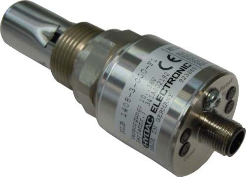
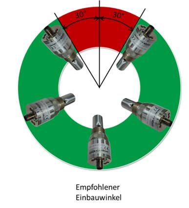
HYDACLAB 1400 CANopen Seite 2 1 Allgemeines Falls Sie Fragen bezüglich der technischen Daten oder Eignung des Gerätes für Ihre Anwendungen haben, wenden Sie sich bitte an unseren Technischen Vertrieb. Das HYDACLAB® wird einzeln auf rechnergesteuerten Prüfplätzen abgeglichen und einem Endtest unterzogen. Es arbeitet beim Einsatz innerhalb der vorgegebenen Spezifikationen (siehe Kapitel 10 „Technische Daten“) einwandfrei. Falls trotzdem Fehler auftreten sollten, wenden Sie sich bitte an den HYDAC Service. Fremdeingriffe in das Gerät führen zum Erlöschen jeglicher Gewährleistungsansprüche. 2 Sicherheitshinweise Der Ölzustandssensor HYDACLAB ist bei bestimmungsgemäßer Verwendung grundsätzlich betriebssicher. Um jedoch Gefahren für Benutzer und Sachschäden infolge falscher Handhabung des Gerätes zu vermeiden, beachten Sie bitte die folgenden Sicherheitshinweise: Überprüfen Sie vor der Inbetriebnahme den ordnungsgemäßen Zustand des Gerätes Lesen Sie vor der Inbetriebnahme die Bedienungsanleitung und stellen Sie sicher, dass das Gerät für Ihre Anwendung geeignet ist. Während des Transportes ist die Vibrations- und Schockfestigkeit deutlich eingeschränkt. Das HYDACLAB darf nur in technisch einwandfreiem Zustand benutzt werden. Die Montagehinweise sind einzuhalten. Die Angaben auf dem Typenschild sind zu beachten. Nach einem Ölwechsel ist ein RESET durchzuführen. Der Sensor sollte nicht in altes Öl montiert werden, ansonsten sind die relativen Änderungsdaten ungültig. Störungssuche und Reparatur sind nur von unserem Kundendienst HYDAC Service durchzuführen. Alle einschlägigen und allgemein anerkannten sicherheitstechnischen Bestimmungen sind einzuhalten. Falsche Handhabung bzw. die Nichteinhaltung von Gebrauchshinweisen oder technischen Angaben kann zu Sach- und / oder Personenschäden führen. 3 Montage Der Sensor kann über den Gewindeanschluss G ¾ direkt in die Hydraulikanlage montiert werden. Es ist darauf zu achten, dass der Sensor nicht in stehendes Öl montiert wird. Es wird empfohlen den Sensor in schräger Lage zu montieren, Einbauwinkel ≥ 30°. Ein senkrechter Einbau mit dem Sensorelement nach unten ist zu vermeiden. Beim Einbau ist darauf zu achten, dass der Sensor vollständig in das Medium eintaucht und dieses frei durch den Sensor zirkulieren kann. Die maximale Strömungsgeschwindigkeit darf 5 m/s nicht überschreiten. Zum Einbau des HYDACLAB bietet HYDAC ELECTRONIC entsprechendes Einbauzubehör an (siehe Kapitel 13.1 „Zubehör Mechanisch“). Der elektrische Anschluss sollte von einem Fachmann nach den jeweiligen Landesvorschriften durchgeführt werden (VDE 0100 in Deutschland). Die HYDACLAB - Sensoren tragen das CE - Zeichen. Eine Konformitätserklärung ist auf Anfrage erhältlich. Die EMV-Normen: EN 61000-6-1, EN 61000-6-2, EN 61000- 6-3 und EN 61000-6-4 werden erfüllt. Die Forderungen der Normen werden nur bei ordnungsgemäßer und fachmännischer Erdung des Sensorgehäuses erreicht. Beim Einschrauben in einen Hydraulikblock ist es ausreichend, wenn der Block über das Hydrauliksystem geerdet ist. Stand 09.06.2021 HYDAC ELECTRONIC GMBH Mat.Nr. 670045

HYDACLAB 1400 CANopen Seite 3 Zusätzliche Montagehinweise, die erfahrungsgemäß den Einfluss elektromagnetischer Störungen reduzieren: Möglichst kurze Leitungsverbindungen herstellen. Leitungen mit Schirm verwenden (z.B. LIYCY 5 x 0,5 mm²). Der Kabelschirm ist in Abhängigkeit der Umgebungsbedingungen fachmännisch und zum Zweck der Störunterdrückung einzusetzen. Direkte Nähe zu Verbindungsleitungen von Leistungsverbrauchern und störenden Elektro- oder Elektronikgeräten ist möglichst zu vermeiden. 4 Begriffsbestimmung In dieser Bedienungsanleitung wird der Begriff relative Dielektrizitätskonstante = / verwendet. Diese ist ein Maß für die Durchlässigkeit eines Stoffes für elektrische Felder in Bezug auf die Durchlässigkeit von Vakuum ). Andere zulässige Bezeichnungen sind relative Permittivität, Permittivitätszahl oder Dielektrizitätszahl. Die relative Dielektrizitätskonstante wird im weiteren Verlauf mit DK abgekürzt. Ein weiterer verwendeter Begriff ist die relative Änderung der Dielektrizitätskonstante = relative Änderung der DK. Die elektrische Leitfähigkeit des Öls wird in nS/m ausgegeben, die Änderung der Leitfähigkeit in %. Der Sättigungsgrad ist ein Maß für den Anteil von Wasser in Öl: Er wird relativ in % dargestellt. 100 % entsprechen dabei dem Punkt, bei dem das Öl vollständig mit Wasser gesättigt ist. Weiteres Wasser wird nicht mehr gelöst und liegt als freies Wasser vor. 5 Funktionsweise Das HYDACLAB CANopen ist ein multifunktionaler Sensor in kompakter Bauform, mit dem eine Zustandserfassung von Ölen online durchgeführt werden kann. Der Anwender wird damit zeitnah über Änderungen des Fluides informiert und kann unzulässigen Betriebsbedingungen umgehend entgegenwirken. Die erfassten Messwerte werden digitalisiert und über das CANopen-Protokoll dem CAN-Feldbussystem zur Verfügung darstellt. Aus den Messwerten für Temperatur, Sättigungsgrad, der relativen Änderung der elektrischen Leitfähigkeit sowie der relativen Änderung der DK ist eine Aussage über die Zustandsänderung eines Öles, z.B. Alterung oder Vermischung mit Fremdfluiden möglich. Die Leitfähigkeits- und DK- Änderung gibt die prozentuale Abweichung von einem am Anfang ermittelten Bezugswert an. Stand 09.06.2021 HYDAC ELECTRONIC GMBH Mat.Nr. 670045
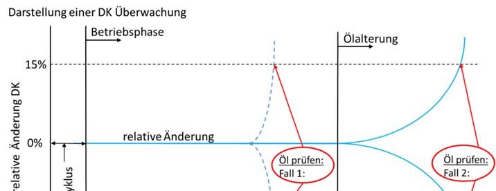
HYDACLAB 1400 CANopen Seite 4 Die LEDs des HYDACLAB geben sowohl Aussagen über die Messwerte des Analog- und Schaltsignals (z.B. Warnung, Alarm) als auch Informationen über den Sensor- und Ölzustand. 5.1 Übersicht der Kontroll-LEDs Parameter änderbar unter Ölzustandsanzeige; siehe Protokollbeschreibung LED 1 LED 2 LED 3 LED 4 Anmerkung /Beschreibung Notiz Stat Cond SP 1 SP 2 Zur Inbetriebnahme Wartephase Starttemperatur 40°C überschreiten Orientierung /Homogenisierung im Arbeitstemperaturbereich, Fittabelle wird gefüllt Orientierung /Homogenisierung außerhalb des Arbeitstemperaturbereichs Betriebsphase im Arbeitstemperaturbereich Betriebsphase außerhalb des Arbeitstemperaturbereichs Führen Sie ein RESET Fehler durch Umgebungsbedingungen und Einbau überprüfen Fehler (tritt z.B. auf bei Messung in Luft) Gerät nicht in der Betriebsphase oder Fehler Sättigungs-, Dielektrizitäts- oder Leitfähigkeitsänderungen im normalen Bereich Warnung: Sättigungs-, Dielektrizitäts- oder Leitfähigkeitsänderungen über der Warnschwelle Alarm: Öl prüfen schnelle Öländerung festgestellt Alarm: Sättigungs-, Dielektrizitäts- oder Öl prüfen Leitfähigkeitsänderungen über der Alarmschwelle Fehlerzustand Schaltausgang aus Schaltausgang ein Wenden Sie sich bitte an den Schwerer Fehler HYDAC-Service Firmware-Update Ein Reset wird durchgeführt Stand 09.06.2021 HYDAC ELECTRONIC GMBH Mat.Nr. 670045
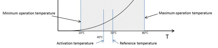
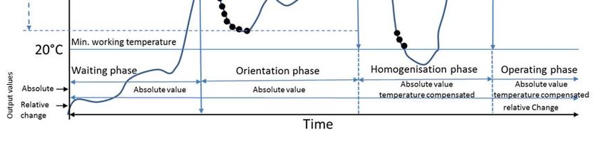
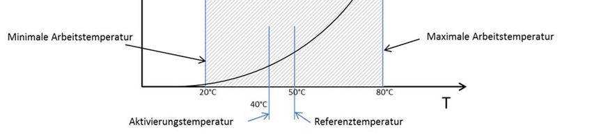
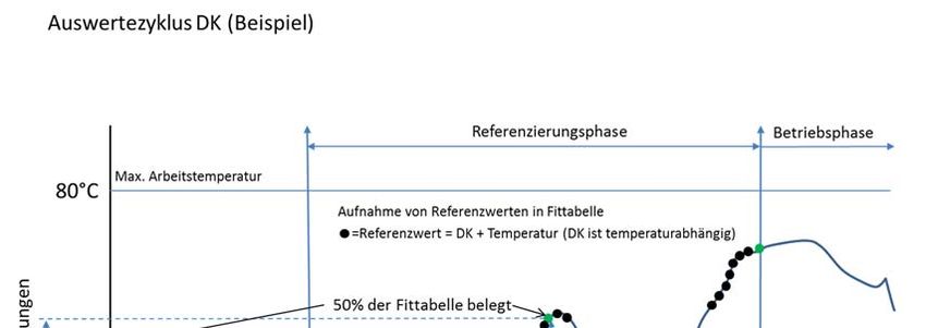
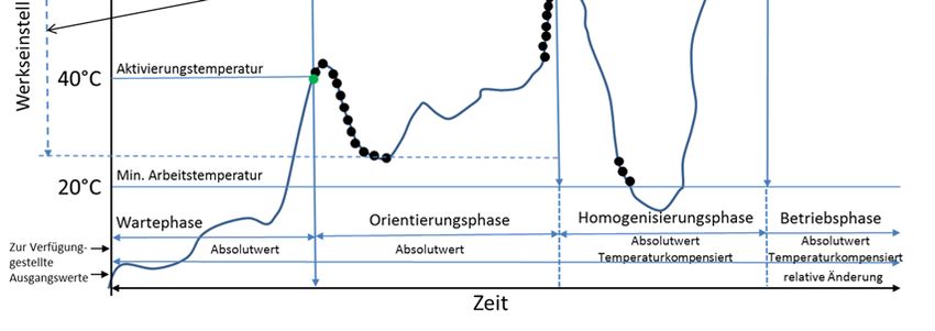
HYDACLAB 1400 CANopen Seite 5 5.1.1.1 Temperatureinstellungen Minimale Arbeitstemperatur (Min working temperature) – Der Sensor ist betriebsbereit, wenn die Arbeitstemperatur über diesem Wert liegt. Maximale Arbeitstemperatur (Max working temperature) – Der Sensor ist betriebsbereit, wenn die Arbeitstemperatur unter diesem Wert liegt. Referenztemperatur (Reference temperature) – Bei der Temperaturkompensation werden die Werte der Leitfähigkeit und der DK auf diese Temperatur bezogen. Aktivierungstemperatur (Activation temperature) – dieser Wert muss einmal überschritten werden, damit der Sensor mit dem Referenzzyklus beginnt. Homogenisierungszeit (Homogenisation time) - hier wird die Dauer der Homogenisierungsphase festgelegt. Nachdem der halbe Arbeitstemperaturbereich durchschritten wird, beginnt die Homogenisierungszeit, siehe auch Abbildung im Kapitel 6. Die Zeit sollte so festgelegt werden, dass gewährleistet ist, dass die Anlage eine komplette Zirkulation, eine Durchmischung des Öls sowie einen kompletten Temperaturablauf absolviert. Werkseinstellung Beschreibung Aktivierungstemperatur 40°C Dieser Wert muss einmal überschritten werden, damit der Sensor beginnt Messdaten aufzuzeichnen Referenztemperatur 50°C Bei der Temperaturkompensation werden die Werte der Leitfähigkeit / DK auf diese Temperatur bezogen Minimale 20°C Unterschreitet die aktuelle Temperatur diesen Wert, Arbeitstemperatur werden die Werte für Leitfähigkeit / DK eingefroren Maximale 80°C Überschreitet die aktuelle Temperatur diesen Wert, Arbeitstemperatur werden die Werte für Leitfähigkeit / DK eingefroren 5.1.1.2 Erläuterung der Temperaturbegriffe: Hinweis: Wenn Sie den Temperaturbereich während des Referenzzyklus ändern, muss KEIN Reset durchgeführt werden, da sich das HYDACLAB automatisch an den neuen Bereich anpasst. 5.1.2 Zurücksetzen (Reset) Referenzzyklus zurücksetzen (Reset reference cycle) bedeutet, dass die Einstellungen beibehalten werden, aber der Lernzyklus gelöscht wird, der für das Referenzieren benötigt wird. Dieser muss daraufhin nochmal durchgeführt werden, z.B. bei einem Ölwechsel. Stand 09.06.2021 HYDAC ELECTRONIC GMBH Mat.Nr. 670045
HYDACLAB 1400 CANopen Seite 6 6 Erstinbetriebnahme Das HYDACLAB beginnt die Datenspeicherung, sobald es mit Spannung versorgt wird und die Temperatur des Mediums erstmals die Aktivierungstemperatur von 40 °C (Werksvoreinstellung) überschreitet. Die Signale für Temperatur und Sättigung stehen direkt nach Inbetriebnahme zur Verfügung. Das Signal für die relative Änderung der Dielektrizitätskonstante und relativen Änderung der elektrischen Leitfähigkeit wird nach Ablauf der Homogenisierungsphase angezeigt. Die Leitfähigkeits- und Dielektrizitätsänderung gibt die prozentuale Abweichung von einem am Anfang ermittelten Bezugswert an. 6.1 Fittabelle Das HYDACLAB beschreibt fortlaufend eine Fittabelle, bei der zu jeder Temperatur die zugehörigen Leitfähigkeits- und Dielektrizitätswerte hinterlegt sind. Anhand dieser Tabelle können dann die gemessenen Werte auf eine Referenztemperatur umgerechnet werden. Außerdem wird die Fittabelle zu einem bestimmten Zeitpunkt, nach der Homogenisierungsphase eingefroren. Diese eingefrorene Fittabelle bildet dann den Bezugsrahmen für die Berechnung der Leitfähigkeits- und Dielektrizitätsänderung. Bei der Auslieferung ist die Tabelle leer. Das Beschreiben der Tabelle erfolgt erst, wenn eine eingestellte Aktivierungstemperatur überschritten wurde. 6.2 Referenzzyklus Während eines Referenzzyklus erfasst das HYDACLAB die Charakteristik des jeweiligen Öles und passt sich den Bedingungen in der gegebenen Applikation an. Es ist deshalb entscheidend, dass während des Referenzzyklus die typischen Betriebsbedingungen, insbesondere alle relevanten Betriebstemperaturbereiche durchlaufen werden. Das Ende des Referenzzyklus ist erreicht, wenn 50 % des Arbeitstemperaturbereiches erfasst sind. Das ist an der LED erkennbar. Während des Referenzzyklus ist dafür zu sorgen, dass das HYDACLAB nur dann mit Spannung versorgt wird, wenn sich die Maschine/ Anlage im normalen Betriebszustand befindet. (Beispielsweise kann die Spannungsversorgung des Sensors an den Pumpenbetrieb gekoppelt werden.) Ein Zurücksetzen sollte erfolgen, wenn nach einer Teil- oder Neubefüllung der Maschine/ Anlage die Werte für die relative Änderung der DK und der elektrischen Leitfähigkeit nicht innerhalb eines Fensters von 5 % liegen. Ursachen dafür können Chargenschwankungen des Öls sein. Stand 09.06.2021 HYDAC ELECTRONIC GMBH Mat.Nr. 670045
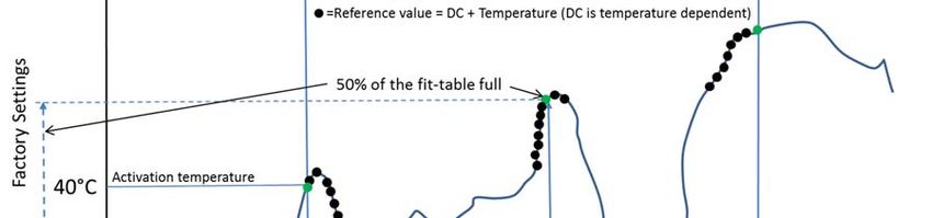
HYDACLAB 1400 CANopen Seite 7 Falls nur geringe Temperaturschwankungen während der Referenzierungsphase vorkommen, könnte es dazu führen, dass die Fittabelle nie zu 50% belegt und somit die Umschaltung der Orientierungsphase in die Homogenisierungsphase verhindert wird. In diesem Fall sollte der min/max Arbeitstemperaturbereich diesbezüglich angepasst werden, damit das Gerät in die Betriebsphase gelangt und eine Änderung der Leitfähigkeit bzw. der DK überwacht und gemeldet kann. 6.3 Zurücksetzen-Taster Taster am Gerät. Dazu die Schraube (siehe Kapitel 12 Geräteabmessungen), Torx T20, lösen und den Taster mit einem spitzen Hilfsmittel, z.B. mit einem Kugelschreiber drücken (Spannungsversorgung muss vorhanden sein!). Der Taster muss 2 Sekunden gedrückt werden. 7 Anschlussbelegung M 12x1,5-pol.: Pin Signal Bezeichnung 1 PE Shield/housing 2 +UB Supply + 3 0V Supply - 4 CAN_H Bus line dominant high 5 CAN_L Bus line dominant low 8 Protokolldaten Comminication Profile CiA DS 301 V4.2 Device Profile CiA DS 404 V1.3 Layer Setting Services and CiA DSP 305 V3.0 Protocol Baudraten 10 kbit .. 1 Mbit gem. DS 305 V3.0 Übertragungsdienste - PDO Messwert als 16 bit integer / 32 bit integer oder 32 bit float; - Transfer Status synchron, asynchron, zyklisch, Messwertänderung, Bereichsgrenzenüberschreitung Node Id/Baudrate Einstellbar über Manufacturer Specific Profile Voreinstellung: Baudrate: 250 kbit Node Id: 1 Weitere Informationen entnehmen Sie bitte der:“Protokoll-Beschreibung CANopen HLB 1400“ Stand 09.06.2021 HYDAC ELECTRONIC GMBH Mat.Nr. 670045
HYDACLAB 1400 CANopen Seite 8 9 Parametrierung Zur Inbetriebnahme des Sensors wird eine elektronische Gerätebeschreibungsdatei benötigt, die sogenannte „EDS“-Datei (Electronic Data Sheet) Die EDS-Datei und die entsprechende Protokollbeschreibung finden Sie zum Download auf unserer Homepage unter: →Produkte→Sensorik→Produktsuche http://www.hydac.com/de-de/produkte/sensorik/show/Material/index.html Bei Eingabe der Materialnummer (9xxxxx) erscheint das entsprechende ZIP-file, welches die EDS-Dateien und die Protokollbeschreibung enthält. 9.1 Parametrierung mit HYDAC Handmessgerät HMG 4000 Schließen Sie den CAN-Sensor mit Standardkabel über die rote Buchse „CAN“ (K) ohne externen Abschusswiderstand am HMG 4000 an. Nach dem Einlesen der EDS-Datei in den Dateimanager können Sie mit Hilfe des Gerätekonfigurationsassistenten die Knoten-ID bzw. Adresse und Baudrate von CANopen- Geräten der HYDAC ELECTRONIC GMBH konfigurieren. Die Betriebsdaten des CAN-Sensors werden über die Einträge des Objektverzeichnisses bereitgestellt. Nähere Informationen entnehmen Sie bitte der HMG 4000 Bedienungsanleitung Stand 09.06.2021 HYDAC ELECTRONIC GMBH Mat.Nr. 670045
HYDACLAB 1400 CANopen Seite 9 10 Technische Daten Arbeitsbereich Sättigungsgrad (rel. Feuchte) 0 .. 100 % Sättigung Temperatur -25 .. +100 °C Dielektrizitätskonstante (DK = εR) 1 .. 10 Änderung der Dielektrizitätskonstante -30 .. 30 % Elektr. Leitfähigkeit 0 .. 100 nS/m Änderung der elektr. Leitfähigkeit -100 .. 200 % Betriebsdruck < 50 bar Druckfestigkeit < 600 bar Strömungsgeschwindigkeit < 5 m/s Medienberührende Teile Edelstahl/Keramik mit aufgedampfter Metall Dichtung Glas mit Dünnfilm-Metallbeschichtung / FKM Ausgangsgröße Ausgangssignal CANopen Protokoll Ausgangsgröße Sättigungsgrad (Feuchtemessung) 0 .. 100 % Kalibriergenauigkeit ± 2 % FS max. Genauigkeit ± 3 % FS typ. 1) Ausgangsgröße Temperatur -25 .. +100 °C Genauigkeit ± 3 % FS max. Ausgangsgröße Dielektrizitätskonstante (εR) 1 .. 10 Genauigkeit ± 5 % FS max. Ausgangsgröße Änderung der Dielektrizitätskonstante ± 30 % v. AW Genauigkeit s.u. 2) Ausgangsgröße elektrische Leitfähigkeit 0 .. 100 nS/m / 0 .. 10 nS/m auswählbar Genauigkeit ± 5 % FS max. Ausgangsgröße Änderung der elektrischen Leitfähigkeit -100 .. 200 % Genauigkeit s.u. 2) Umgebungsbedingungen Nenntemperaturbereich +20 .. +80 °C Lagertemperatur -30 .. +100 °C Medienverträglichkeit Geeignet für Hydraulik- und Schmieröle - Zeichen EN 61000-6-1 / 2 / 3 / 4 Viskositätsbereich 1 .. 5000 cSt Schockfestigkeit nach DIN EN 60068-2-27 50 g / 11 ms / Halbsinus Vibrationsbeständigkeit nach DIN EN 60068-2-6 bei 5 .. 2000 10 g / Sinus Hz Schutzart nach DIN EN 60529 IP 67 3) Sonstige Größen Versorgungsspannung UB 10 .. 36 V DC Restwelligkeit Versorgungsspannung 5% Stromaufnahme ohne Ausgänge max. 100 mA Mechanischer Anschluss G ¾ A ISO 1179-2 Anzugsdrehmoment 30 Nm Elektrischer Anschluss M12x1, 5 polig Gehäuse Edelstahl Gewicht ca. 215 g FS (Full Scale); bezogen auf den vollen Messbereich, AW (Anfangs Wert) 1) Die maximale Genauigkeit der Feuchtemessung ist stark abhängig von der Ölsorte bzw. der Additivierung. Genauere Angaben hierzu auf Anfrage. 2) Die Genauigkeiten bei der Bestimmung der Änderung der Dielektrizitätszahl und elektr. Leitfähigkeit sind abhängig von der Applikation, der Ölsorte und der Eigenkalibrierung des Sensors. Detaillierte Informationen hierzu auf Anfrage. 3) Bei montierter Kupplungsdose entsprechender Schutzart Stand 09.06.2021 HYDAC ELECTRONIC GMBH Mat.Nr. 670045
HYDACLAB 1400 CANopen Seite 10 11 Bestellangaben H L B 1 4 J 8 – 00F11 - 000 Messgrößen 4 = 4 Messgrößen: - Sättigung (rel. Feuchte) - Temperatur - elektrische Leitfähigkeit und deren relative Änderung - Dielektrizitätskonstante DK und deren relative Änderung Mechanischer Anschluss J = G3/4A ISO 1179-2 Elektrischer Anschluss 8 = Gerätestecker M12x1, 5-pol. (ohne Kupplungsdose) Signal / Schnittstelle F11 = CANopen Modifikationsnummer 000 = Standard 12 Geräteabmessungen Stand 09.06.2021 HYDAC ELECTRONIC GMBH Mat.Nr. 670045
HYDACLAB 1400 CANopen Seite 11 13 Zubehör 13.1 Mechanisch ZBM 21 (Flow) Adapter zum Einbringen des Ölzustands-Sensors HYDACLAB in eine Leitung G 1/2”. Anmerkung: Nur geeignet für: max. Betriebsdruck < 50 bar und max. Strömungsgeschwindigkeit < 5 m/s. Bestell-Nr.: 3244260 HYDACLAB 13.2 Elektrisch ZBE 08 (5-pol.) Kupplungsdose M12x1, abgewinkelt Kabeldurchmesser: 2,5 .. 6,5 mm Material-Nr.: 6006786 ZBE 08-02 (5-pol.) Kupplungsdose M12x1, abgewinkelt mit 2m Leitung, Material-Nr.: 6006792 ZBE 08-05 (5-pol.), Kupplungsdose M12x1, abgewinkelt mit 5m Leitung Material-Nr.: 6006791 Farbkennung: Pin 1: braun Pin 2: weiß Pin 3: blau Pin 4: schwarz Pin 5: grau Stand 09.06.2021 HYDAC ELECTRONIC GMBH Mat.Nr. 670045
HYDACLAB 1400 CANopen Seite 12 ZBE 08S-02 (5-pol.) Kupplungsdose M12x1, abgewinkelt mit 2 m Leitung, geschirmt Material-Nr.: 6019455 ZBE 08S-05 (5-pol.) Kupplungsdose M12x1, abgewinkelt mit 5 m Leitung, geschirmt Material-Nr.: 6019456 ZBE 08S-10 (5-pol.) Kupplungsdose M12x1, abgewinkelt mit 10 m Leitung, geschirmt Material-Nr.: 6023102 Farbkennung: Pin 1: braun Pin 2: weiß Pin 3: blau Pin 4: schwarz Pin 5: grau ZBE 30-02 Verbindungskabel 12x1 Stecker/Buchse 5-polig, mit 2 m Leitung Material-Nr.: 6040851 ZBE 30-05 Verbindungskabel 12x1 Stecker/Buchse 5-polig, mit 5 m Leitung Material-Nr.: 6040852 Bus-Terminierung Abschlusswiderstand zum Abschluss der CAN-Busleitung Material-Nr.: 6178198 Y-Verteiler Adapter für HMG 4000 zum Anschluss von CAN / HCSI Sensoren Material-Nr.: 6178196 Stand 09.06.2021 HYDAC ELECTRONIC GMBH Mat.Nr. 670045
HYDACLAB 1400 CANopen Seite 13 14 Wichtige Hinweise auf einen Blick Der montierte Sensor muss vollständig in das Medium eintauchen, damit dieses frei durch den Sensor zirkulieren kann. Achten Sie beim Einbau ohne den Montageblock ZBM 21 darauf, dass das Einströmen des Mediums durch den Einbau nicht beeinträchtigt wird. Zwischen der Stirnseite des Sensorkopfes und der gegenüberliegenden Rohr- bzw. Gehäusewand muss ein Mindestabstand von 10 mm eingehalten werden. Stellen Sie einen stetigen Durchfluss sicher und vermeiden Sie die Bildung von Luftblasen. Bei stehendem Öl sind erhöhte Messabweichungen möglich. Grundsätzlich ist HYDACLAB nur dann mit Spannung zu versorgen, wenn normaler Volumenstrom gewährleistet ist. D.h. trennen Sie das HYDACLAB von der Spannungsversorgung sobald die Anlage abgeschaltet wird, außer Betrieb geht oder eine zeitlich nennenswerte Unterbrechung des Volumenstromes eintritt. Beachten Sie, dass während des Referenzzyklus die typischen Betriebsbedingungen herrschen, d.h. alle betriebsrelevanten Zustände durchlaufen werden. Der Start des Referenzzyklus beginnt sobald HYDACLAB mit Spannung versorgt ist und anschließend die Temperatur des Mediums erstmalig 40°C (Werkseinstellung) überschreitet. Vermeiden Sie während des Referenzzyklus Vermischungen des Fluids oder Auffüllen von Neuöl. Bei Ölwechsel oder gravierender Änderung der Umgebungsbedingungen sollte ein Reset durchgeführt werden. 15 Haftung Diese Bedienungsanleitung haben wir nach bestem Wissen und Gewissen erstellt. Es ist dennoch nicht auszuschließen, dass trotz größter Sorgfalt sich Fehler eingeschlichen haben könnten. Haben Sie bitte deshalb Verständnis dafür, dass wir, soweit sich nachstehend nichts anderes ergibt, unsere Gewährleistung und Haftung - gleich aus welchen Rechtsgründen - für die Angaben in dieser Bedienungsanleitung ausschließen. Insbesondere haften wir nicht für entgangenen Gewinn oder sonstige Vermögensschäden. Dieser Haftungsausschluss gilt nicht bei Vorsatz und grober Fahrlässigkeit. Er gilt ferner nicht für Mängel, die arglistig verschwiegen wurden oder deren Abwesenheit garantiert wurde sowie bei schuldhafter Verletzung von Leben, Körper und Gesundheit. Sofern wir fahrlässig eine vertragswesentliche Pflicht verletzen, ist unsere Haftung auf den vorhersehbaren Schaden begrenzt. Ansprüche aus Produkthaftung bleiben unberührt. Im Falle der Übersetzung ist der Text der deutschen Originalbedienungsanleitung der allein gültige. Stand 09.06.2021 HYDAC ELECTRONIC GMBH Mat.Nr. 670045
HYDACLAB 1400 CANopen Seite 14 Notizen Stand 09.06.2021 HYDAC ELECTRONIC GMBH Mat.Nr. 670045
HYDACLAB 1400 CANopen Seite 15 16 Kontakt HYDAC ELECTRONIC GMBH Hauptstr. 27 D-66128 Saarbrücken Germany Web: www.hydac.com E-Mail: electronic@hydac.com Tel.: +49 (0)6897 509-01 Fax.: +49 (0)6897 509-1726 HYDAC Service Für Fragen zu Reparaturen steht Ihnen der HYDAC Service zur Verfügung. HYDAC SERVICE GMBH Hauptstr. 27 D-66128 Saarbrücken Germany Tel.: +49 (0)6897 509-1936 Fax.: +49 (0)6897 509-1933 Anmerkung Die Angaben in dieser Bedienungsanleitung beziehen sich auf die beschriebenen Betriebsbedingungen und Einsatzfälle. Bei abweichenden Einsatzfällen und/oder Betriebsbedingungen wenden Sie sich bitte an die entsprechende Fachabteilung. Bei technischen Fragen, Hinweisen oder Störungen nehmen Sie bitte Kontakt mit Ihrer HYDAC- Vertretung auf. Stand 09.06.2021 HYDAC ELECTRONIC GMBH Mat.Nr. 670045
Fluid Condition Sensor HYDACLAB HLB 1400 CANopen Instruction manual (Translation of original instructions) Part no.: 670045 / Status: 2021-06-09
Contents
1 General ....................................................................................................................................... 2
2 Safety Information ...................................................................................................................... 2
3 Installation .................................................................................................................................. 2
4 Definition of the Terms ............................................................................................................... 3
5 Function ...................................................................................................................................... 3
 5.1 Overview of control LEDs .................................................................................................... 4
 5.1.2 Reset .............................................................................................................................. 5
6 Start-up ....................................................................................................................................... 6
 6.1 Fit table ................................................................................................................................ 6
 6.2 Reference cycle ................................................................................................................... 6
 6.3 Reset Button ........................................................................................................................ 7
7 PIN connection ........................................................................................................................... 7
8 Protocol data .............................................................................................................................. 7
9 Parameterisation ........................................................................................................................ 8
 9.1 Parameterisation by means of HYDAC portable measuring unit HMG 4000 ....................... 8
10 Technical Data ........................................................................................................................... 9
11 Order details ............................................................................................................................. 10
12 Device Dimensions ................................................................................................................... 10
13 Equipment ................................................................................................................................ 11
 13.1 Mechanical ......................................................................................................................... 11
 13.2 Electric ............................................................................................................................... 11
14 Important tips at a glance ......................................................................................................... 13
15 Liability ..................................................................................................................................... 13
16 Contact information .................................................................................................................. 15
HYDACLAB 1400 CANopen Page 2 1 General If you have any queries regarding technical details or the suitability of the instrument for your application, please contact our Technical Sales department. HYDACLAB® sensors have been individually calibrated on computer-aided test benches and subjected to a final test. They operate perfectly when used according to the specifications (see chap. 10 "Technical Data"). However, if there is a cause for complaint, please contact HYDAC Service. Interference by anyone other than HYDAC personnel will invalidate all warranty claims. 2 Safety Information The Fluid Condition Sensor HYDACLAB® presents no safety concerns when operated in accordance with this user manual. However, in order to avoid any risk to the operator or any damage due to incorrect handling of the unit, please adhere strictly to the following safety instructions: Before commissioning, check that the unit is in perfect condition. Before commissioning, please read the operating instructions. Ensure that the unit is suitable for your application. During transportation, extra care must be taken to protect the unit from vibration and shock. The HYDACLAB must not be put into service if any known technical defects are apparent. The unit must be installed according to the instructions. The information on the type code label must be noted. After an oil change, RESET must be carried out. The sensor should not be mounted in combination with old oil as all relative data changes will thus become void. Troubleshooting and repair work may only be carried out at the HYDAC Service department. All relevant and generally recognised safety requirements must be adhered to. If the instrument is not handled correctly, or if the operating instructions and specifications are not adhered to, damage to property or personal injury can result. 3 Installation The sensor can be installed directly in the hydraulic system via the threaded G ¾ connection. Please ensure the sensor is not mounted into standing oil. It is recommended to fit the sensor in inclined position, fitting angle ≥ 30°. Please avoid vertical fitting of the sensor with the sensor element pointing downwards. When fitting, ensure that the sensor is completely submerged in the fluid and that the fluid can circulate freely through the sensor. The maximum circulation speed should not exceed 5 m/s. For installation of the HYDACLAB, HYDAC ELECTRONIC offers the appropriate mounting accessories (see chap. 13.1, "Mechanical Accessories"). The electrical connection must be carried out by a qualified electrician according to the relevant regulations of the country concerned (VDE 0100 in Germany). HYDACLAB sensors are CE marked. A declaration of conformity is available on request. The relevant EMC standards EN 61000-6-1; EN 61000-6-2, EN 61000-6-3, EN 6100-6-4 are met. However, the stipulations of those standards are met only if the sensor's housing has been correctly earthed by a qualified electrician. When fitted into a hydraulic block, earthing the block via the hydraulic system is sufficient. Recommended Additional installation instructions which, from mounting angle experience, reduce the effect of electromagnetic interference: Make line connections as short as possible. Use shielded cabling (e.g. LIYCY 5 x 0.5 mm²). Version 2021-06-09 HYDAC ELECTRONIC GMBH Part no. 670045
HYDACLAB 1400 CANopen Page 3 The cable shielding must be fitted by qualified personnel, subject to the environmental conditions and with the aim of suppressing interference. Keep the unit well away from the electrical supply lines of power equipment, as well as from any electrical or electronic equipment causing interference. 4 Definition of the Terms The term of "relative dielectric constant" = / is used in this operating manual. It is the parameter for the permeability of a substance for electric fields with regards to the permeability of vacuum . Other permitted definitions are "relative permitivity", "permitivity value" or "dielectric value". The relative dielectric constant will be referred to hereinafter as DC. A further term used in hereinafter is the relative change of the dielectric constant = relative change of the DC. The electric conductivity of the oil is displayed in nS/m, the change of conductivity is displayed in %. The saturation level is a parameter for the concentration of water in oil: it is displayed relatively in %. Consequently, 100 % correspond with the point where the oil is fully saturated with water. Further water will no more be dissolved by the oil and there will be a presence of free water in the oil. 5 Function HYDACLAB® CANopen is a compact, multi-functional sensor for determining the condition of oils online. The user is thus informed in real time of changes in the fluids and can implement measures against improper operating conditions without delay. The recorded measured values are digitized and made available to the CAN field bus system via the CANopen protocol. Changes in fluid condition that might occur due to ageing or mixing with other fluids, for example, are indicated by measuring the temperature, the saturation level, the relative change of electrical conductivity and the relative change in dielectric constant (also referred to as DC). The change of conductivity and of the DC results in a deviation of the reference value in percent determined in the beginning. The LEDs of HYDACLAB indicate the information on the measured values of the analogue and the switching signal (i.e. warning, alert) as well as the information on the sensor and the oil condition. Version 2021-06-09 HYDAC ELECTRONIC GMBH Part no. 670045
HYDACLAB 1400 CANopen Page 4 5.1 Overview of control LEDs Parameters adjustable under oil condition indication; see protocol description LED 1 LED 2 LED 3 LED 4 Note / Description Note Stat Cond SP 1 SP 2 For commissioning, please Waiting phase exceed start temperature of 40°C. Orientation/ Homogenisation within the operation temperature range, fit table is filled in Orientation / Homogenisation outside the operation temperature range Operating phase within the operating temperature range Operating phase outside the operating temperature range Error Perform a RESET Please check ambient conditions and fitting Error (occurs when measuring in air, for example) Device is not in the operating phase or an error has occurred Saturation, dialectic or conductivity changes within normal range Warning: Saturation, dielectric or conductivity changes exceed the warning threshold Alert: Check the oil rapid oil change has been detected Alert: Saturation, dielectric or conductivity changes Check the oil exceed the alert threshold Error status Switch output off Switch output on Please contact HYDAC Serious error Service. Firmware update A reset is being performed Version 2021-06-09 HYDAC ELECTRONIC GMBH Part no. 670045
HYDACLAB 1400 CANopen Page 5 5.1.1.1 Temperature settings Min working temperature - The sensor is ready for use as soon as the working temperature has exceeded this value. Max working temperature - The sensor is ready for use as soon as the working temperature has fallen below this value. Reference temperature - In the event of temperature compensation the values of the conductivity and the DC will refer to this temperature. Activation temperature - This value must be exceeded once in order for the sensor to initiate its reference cycle. Homogenisation time - The duration of the homogenisation phase will be defined during this period. After having passed through half of the working temperature range, the homogenisation time starts, see also figure chap. 6 The time should be defined in order to ensure that the system carries out a complete circulation, a mixing of the oil and a complete temperature ramp. Default settings Description Activation temperature 40°C The value must be exceeded once to make the sensor start recording the measured values. Reference 50°C In the event of temperature compensation the values temperature of the conductivity / DC will refer to this temperature. Minimum operation 20°C Should the operation range lie below this range, the temperature values for conductivity/DC will be frozen. Maximum operation 80°C Should the operation range exceed this range, the temperature values for conductivity / DC will be frozen. 5.1.1.2 Explanation of Terms regarding Temperature: Notice: If the temperature range is changed during the reference cycle, NO reset needs to be performed, as the HYDACLAB will automatically adapt to the new range. 5.1.2 Reset Reset reference cycle means that all settings will be kept, except the learning cycle which is required for referencing, will be deleted. Thus, it must be performed again, i.e. for an oil change. Version 2021-06-09 HYDAC ELECTRONIC GMBH Part no. 670045
HYDACLAB 1400 CANopen Page 6 6 Start-up HYDACLAB starts its data storage as soon as it is connected to a voltage supply and the fluid temperature exceeds its activating temperature of 40 °C (factory settings) for the first time. The output signals for temperature and saturation are available immediately after sensor startup. The signal for relative change of the DC and relative change of the electric conductivity is displayed after the homogenisation phase has expired. Both the conductivity and the dielectric change result in a deviation in percent from the reference value determined in the beginning. 6.1 Fit table HYDACLAB continuously writes on a fit table on which the respectively defined conductivity and dielectric values for each temperature are stored. By means of this table the measured values can be converted to a reference temperature. Furthermore, the fit table will be frozen at a certain moment following the homogenisation phase. This frozen fit table provides a reference framework for the calculation oft the conductivity and dielectric change. At the delivery of the device the table is empty. The table is not written onto before the set activating temperature has been exceeded. 6.2 Reference cycle During the reference cycle the HYDACLAB records the characteristics of the respective oil and adapts to the conditions of the relevant application. It is therefore essential that typical operating conditions, particularly all relevant operating temperature ranges, are run through during the reference phase. The end of the reference cycle is reached, when 50 % of the working temperature have been detected. This will be indicated by the LED. During the reference phase, the user must therefore ensure that the HYDACLab is only supplied with voltage if the operating conditions in the machine/system are normal. (For example, the supply voltage of the sensor can be linked to the pump operation.) The sensor should be reset if, after the machine/system has been part-filled or re-filled, the values for the relative change in dielectric constant and the electric conductivity do not fall within a window of ± 5 %. This can be caused by variations in oil characteristics in different oil batches. Version 2021-06-09 HYDAC ELECTRONIC GMBH Part no. 670045
HYDACLAB 1400 CANopen Page 7 If very low temperature fluctuations occur during the reference phase, this could have the consequence that the fit table is never occupied up to 50% which means that switching from the orienting phase to the homogenisation phase becomes impossible. In this case, the min/max working temperature range should be adapted in a way to ensure that the device is able to switch to the operation phase and that any change in conductivity or DC can be monitored and reported. 6.3 Reset Button Button on the device. Loosen the screw (see chap. 12 "Device Dimensions"), Torx T20, and press the button by means of a pointed object (pen or similar). Ensure the power supply is switched on! Hold the push-button for 2 seconds. 7 PIN connection M12x1, 5 pole: Pin Signal Designation 1 PE Shield/housing 2 +UB Supply + 3 0V Supply - 4 CAN_H Bus line dominant high 5 CAN_L Bus line dominant low 8 Protocol data Comminication Profile CiA DS 301 V4.2 Device profile CiA DS 404 V1.3 Layer setting services and CiA DSP 305 V3.0 protocol Baud rates 10 kbit .. 1 Mbit acc. to. DS 305 V3.0 Transmission services - PDO Measured value as 16 bit integer / 32 bit integer, or 32 bit - Transfer float; status synchronous, asynchronous, cyclical, measured value change, exceeding boundaries Node ID/ Baud rate Settable via Manufacturer Specific Profile Default settings: Baud rate: 250 kbit Node Id:1 Further information can be taken from the "Protocol description HLB 1400" Version 2021-06-09 HYDAC ELECTRONIC GMBH Part no. 670045
HYDACLAB 1400 CANopen Page 8 9 Parameterisation For the commissioning of the sensor an electronic device description file is necessary, known as "EDS" file (Electronic Data Sheet) The EDS file and its corresponding protocol description can be downloaded from our internet site using the path:→Products→Sensors→Product finder http://www.hydac.com/uk-en/products/sensors/show/Material/index.html Entering the part number (9xxxxx) the corresponding ZIP file appears, containing the EDS files and their respective protocol description. 9.1 Parameterisation by means of HYDAC portable measuring unit HMG 4000 Connect the CAN sensor to HMG 4000 using standard cable via the red socket "CAN" (K) without external terminating resistor. After importing the EDS file into the file manager you can configure the Node ID or the address and Baud rate of all CANopen devices by HYDAC ELECTRONIC GMBH by means of the device configuration assistant. The operation data of the CAN sensor are provided via the entries in the object directory. More detailed information can be taken from the HMG 4000 operation manual Version 2021-06-09 HYDAC ELECTRONIC GMBH Part no. 670045
HYDACLAB 1400 CANopen Page 9 10 Technical Data Working range Saturation level (relative humidity) 0 .. 100 % saturation Temperature -25 .. +100 °C Dielectric constant (DC = εR) 1 .. 10 Change in the dielectric constant -30 .. 30 % Electrical conductivity 0 .. 100 nS/m Change of electr. conductivity -100 .. 200 % Operating pressure < 50 bar Pressure resistance < 600 bar Flow velocity < 5 m/s Parts in contact with the fluid Stainless steel / ceramic with vacuum-metallised seal Glass with thin-film metallic coating / FKM Output variable Output signal CANopen protocol Output data - Saturation level (humidity measurement) 0 .. 100 % Calibration accuracy ± 2 % FS max. Accuracy ± 3 % FS typ. 1) Output variable temperature -25 .. +100 °C Accuracy ± 3 % FS max. Output variable dielectric constant (εR) 1 .. 10 Accuracy ± 5 % FS max. Output variable change of dielectric constant ± 30 % v. AW Accuracy See below 2) Output variable electric conductivity 0 .. 100 nS/m / 0 .. 10 nS/m selectable Accuracy ± 5 % FS max. Output variable change of electrical conductivity -100 .. 200 % Accuracy See below 2) Environmental Conditions Nominal temperature range +20 .. +80°C Storage temperature -30 .. +100 °C Fluid compatibility Suited for hydraulic and lubrication oils mark EN 61000-6-1 / 2 / 3 / 4 Viscosity range 1 .. 5000 cSt Shock resistance acc. to DIN EN 60068-2-27 50 g / 11 ms / half sine Vibration resistance acc. to 10 g / sine DIN EN 60068-2-6 at 5 .. 2000 Hz Protection type acc. to DIN EN 60529 IP 67 3) Other data Supply voltage UB 10 .. 36 V DC Residual ripple of supply voltage 5% Current consumption excluding outputs max. 100 mA Mechanical connection G ¾ A ISO 1179-2 Tightening torque 30 Nm Electrical connection M12x1, 5 pole Case Stainless steel Weight approx. 215 g FS (Full Scale) = relative to complete measuring range, IV (Initial Value) 1) The max. accuracy achievable when measuring relative humidity is heavily dependent on the type of fluid or fluid additive. More precise information on this is available on request. 2) The accuracies when defining the change of dielectric constant and the electrical conductivity depend on the application, the oil type and the auto-calibration of the sensor. Detailed information available on request. 3) With mounted mating connector in corresponding protection type Version 2021-06-09 HYDAC ELECTRONIC GMBH Part no. 670045
HYDACLAB 1400 CANopen Page 10 11 Order details H L B 1 4 J 8 – 00F11 - 000 Measured variables 4 = 4 Measured variables - Saturation (relative humidity) - Temperature - Electric conductivity and relative change - Dielectric constant (DK) and relative change Mechanical connection J = G3/4A ISO 1179-2 Electrical connection 8 = Plug, M12x1, 5 pole (mating connector not supplied) Signal / Interface F11 = CANopen Modification number 000 = standard 12 Device Dimensions Screw Torx T20 Plug connection M12x1 Version 2021-06-09 HYDAC ELECTRONIC GMBH Part no. 670045
HYDACLAB 1400 CANopen Page 11 13 Equipment 13.1 Mechanical ZBM 21 (Flow) Adapter to connect the HYDACLAB fluid condition sensor in a G 1/2” line Note: suitable only for max. operating pressure < 50 bar and max circulation speed < 5 m/s. Order no.: 3244260 HYDACLAB 13.2 Electric ZBE 08 (5 pole) Mating connector M12x1, right angle Cable diameter: 2.5 .. 6.5 mm Part No.: 6006786 ZBE 08-02 (5 pole) Mating connector M12x1, right-angle with 2 m cable, Part No.: 6006792 ZBE 08-05 (5 pole) Mating connector M12x1, right-angle with 5 m cable Part No.: 6006791 Colour code: Pin 1: brown Pin 2: white Pin 3: blue Pin 4: black Pin 5: grey Version 2021-06-09 HYDAC ELECTRONIC GMBH Part no. 670045
HYDACLAB 1400 CANopen Page 12 ZBE 08S-02 (5 pole) Mating connector M12x1, right-angle with 2 m cable, screened Part No.: 6019455 ZBE 08S-05 (5 pole) Mating connector M12x1, right-angle with 5 m cable, screened Part No.: 6019456 ZBE 08S-10 (5 pole) Mating connector M12x1, right-angle with 10 m cable, screened Part No.: 6023102 Colour code: Pin 1: brown Pin 2: white Pin 3: blue Pin 4: black Pin 5: grey ZBE 30-02 Connection cable M12x1, plug/socket, 5 pole with 2 m cable Material-No.: 6040851 ZBE 30-05 Connection cable M12x1, plug/socket, 5 pole with 5 m cable Part No.: 6040852 Bus termination Termination resistor for the termination of the CANbus line Material-No.: 6178198 Y distributor Adapter from HMG 4000 for the connection of CAN / HCSI sensors Part no.: 6178196 Version 2021-06-09 HYDAC ELECTRONIC GMBH Part no. 670045
HYDACLAB 1400 CANopen Page 13 14 Important tips at a glance Once fitted, the sensor must be completely immersed in the fluid in a way that the fluid can circulate freely through the sensor. When installing without the mounting block ZBM 21, make particularly sure that the flow of fluid is not impeded by the installation. There must be a minimum distance of 10 mm between the front end of the sensor head and the opposite wall of the pipe/housing. Ensure there is constant flow and prevent the formation of air bubbles. With standing oil, variations in measurement may increase. In principle the HYDACLAB must only be supplied with voltage if normal flow is guaranteed. In other words, disconnect the HYDACLAB from the supply voltage as soon as the system is switched off, stops operating or if the flow is interrupted for a significant period. Ensure that the operating conditions are typical during the reference cycle i.e. the whole range of conditions relevant to operation are included. The reference cycle starts as soon as HYDACLAB is supplied with voltage and the fluid temperature exceeds 40°C for the first time (default settings). During the reference cycle, please avoid mixing the fluid and filling up with new oil. In the event of oil change or serious alteration in the ambient conditions, the unit should be reset. 15 Liability This instruction manual was made to the best of our knowledge. Nevertheless and despite the greatest care, it is possible that it may contain errors. Therefore please understand that in the absence of any provisions to the contrary hereinafter our warranty and liability – for any legal reasons whatsoever – are excluded in respect of the information in this instruction manual. In particular, we shall not be liable for lost profit or other financial loss. This exclusion of liability does not apply in cases of intent or gross negligence. Moreover, it does not apply to defects which have been deceitfully concealed or whose absence has been guaranteed, nor in cases of culpable harm to life, physical injury and damage to health. If we negligently breach any material contractual obligation, our liability shall be limited to foreseeable damage. Claims due to the product liability shall remain unaffected. In cases where the translation is used, the text of the original German Assembly and Repair Instructions shall prevail. Version 2021-06-09 HYDAC ELECTRONIC GMBH Part no. 670045
HYDACLAB 1400 CANopen Page 14 Notes Version 2021-06-09 HYDAC ELECTRONIC GMBH Part no. 670045
HYDACLAB 1400 CANopen Page 15 16 Contact information HYDAC ELECTRONIC GMBH Hauptstr. 27 D-66128 Saarbruecken Germany Web: www.hydac.com E-mail: electronic@hydac.com Phone: +49(0)6897 / 509-01 Fax.: +49 (0)6897 509-1726 HYDAC Service For enquiries regarding repairs, please contact HYDAC Service. HYDAC SERVICE GMBH Hauptstr. 27 D-66128 Saarbruecken Germany Phone: +49 (0)6897 509-1936 Fax.: +49 (0)6897 509-1933 Note The information in this manual relates to the operating conditions and applications described. For applications or operating conditions not described please contact the relevant technical department. If you have any questions or suggestions or encounter any problems of a technical nature, please contact your HYDAC representative. Version 2021-06-09 HYDAC ELECTRONIC GMBH Part no. 670045
Sie können auch lesen