Modell der Diesellokomotive Baureihe 290
←
→
Transkription von Seiteninhalten
Wenn Ihr Browser die Seite nicht korrekt rendert, bitte, lesen Sie den Inhalt der Seite unten
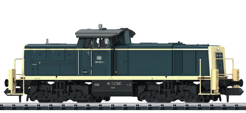
Modell der Diesellokomotive Baureihe 290
D   GB USA   F                              16295
2
Inhaltsverzeichnis                Seite   Sommaire                                          Page
Informationen zum Vorbild             4   Informations concernant le modèle réelle              5
Sicherheitshinweise                   6   Remarques importantes sur la sécurité                14
Wichtige Hinweise                     6   Information importante                               14
Funktionen                            6   Fonctionnement                                       14
Hinweise zum Digitalbetrieb           6   Remarques relatives au fonctionement en mode digital 14
Schaltbare Funktionen                 7   Fonctions commutables                                15
Configurations Variablen (CVs)        8   Variables de configuration (CVs)                     16
Wartung und Instandhaltung           18   Entretien et maintien                                18
Ersatzteile                          22   Pièces de rechange                                   22

Table of Contents                 Page
Information about the prototype      4
Safety Notes                        10
Important Notes                     10
Functions                           10
Notes on digital operation          10
Controllable Functions              11
Configuration Variables (CVs)       12
Service and maintenance             18
Spare Parts                         22

                                                                                                    3
Informationen zum Vorbild Information about the Prototype Neben der Einführung von neuen Diesellokomotiven für den In addition to introducing new diesel locomotives for road Streckendienst musste die Deutsche Bundesbahn als Ersatz service, the German Federal Railroad had to procure new für die Dampflokomotiven auch neue Lokomotiven für den locomotives for switching work as replacements for steam Rangierdienst beschaffen. Neben der Baureihe V 60, die in locomotives. After the class V 60, which was placed into den 1950er-Jahren in Dienst gestellt wurde, zeichnete sich service in the 1950’s, the need became acute for a more der Bedarf nach einem leistungsfähigeren Loktyp ab. Diese powerful locomotive type. This gap was closed starting in Lücke wurde ab 1964 mit der von der Firma MaK entwickelten 1964 with the class V 90 developed by the firm MaK. The 12 Baureihe V 90 geschlossen. Der eingebaute 12-Zylinder- cylinder diesel motor built into the locomotive was derived Dieselmotor, der von dem Motor aus der V 100 abgeleitet ist, from the motor for the class V 100 and provided enough stellte mit einer Leistung von knapp 810 kW (1.100 PS) genü- power at just 810 kilowatts / 1,100 horsepower to fulfill this gend Potenzial zur Erfüllung dieser Aufgabe zur Verfügung. task. The V 90 was switch engine pure and simple and thus Als reine Rangierlok wurde bei der V 90 auf den Einbau einer dispensed with having a train heating system. From 1968 on Zugheizung verzichtet. Ab 1968 wurde die Lok bei der DB als this locomotive was designated by the DB as the class 290. Baureihe 290 eingereiht. 4
Informations concernant la locomotive réelle
A la fin de la traction vapeur, la Deutsche Bundesbahn se vit
obligée non seulement d’introduire de nouvelles locomotives
diesel pour le service de ligne, mais également d’acquérir de
nouvelles machines de manœuvre. Outre la série V 60 mise
en service dans les années 1950, se fit sentir le besoin d’un
type de locomotive plus puissant. La série V 90, conçue par la
firme MaK, vint combler cette lacune à partir de 1964. Avec
une puissance de tout juste 810 kW (1.100 ch), son moteur
diesel à 12 cylindres - dérivé de celui de la V 100 - offrait un
potentiel suffisant pour satisfaire à cette exigence. La V 90
étant destinée exclusivement aux manœuvres, on se dispensa
de l’installation d’un dispositif de chauffage pour le train. A
partir de 1968, la locomotive fut immatriculée dans la
série 290 de la DB.

                                                                   5
Sicherheitshinweise • Gewährleistung und Garantie gemäß der beiliegenden
• Die Lok darf nur mit einem dafür bestimmten Betriebssys- Garantieurkunde.
tem eingesetzt werden. • Entsorgung: www.maerklin.com/en/imprint.html
• Die Lok darf nicht mit mehr als einer Leistungsquelle Funktionen
versorgt werden. • Eingebaute Elektronik zum wahlweisen Betrieb mit
• Beachten Sie unbedingt die Sicherheitshinweise in der konventionellem Gleichstrom-Fahrgerät (max. ±12 Volt),
Bedienungsanleitung zu Ihrem Betriebssystem. Trix Systems, Trix Selectrix (SX1) und Selectrix 2 (SX2)
• Analog 14 Volt=, digital 22 Volt~. oder Digitalsystemen nach NMRA-Norm.
• Für den konventionellen Betrieb der Lok muss das • Automatische Systemerkennung zwischen Digital- und
Anschlussgleis entstört werden. Dazu ist das Entstörset Analog-Betrieb.
14972 zu verwenden. Für Digitalbetrieb ist das Entstörset • Keine automatische Systemerkennung zwischen den
nicht geeignet. Digital-Systemen.
• Setzen Sie das Modell keiner direkten Sonneneinstrah- • Dreilicht-Spitzensignal vorne, zwei rote Schlusslichter
lung, starken Temperaturschwankungen oder hoher hinten, mit der Fahrtrichtung wechselnd.
Luftfeuchtigkeit aus.
Hinweise zum Digitalbetrieb
• Das verwendete Gleisanschlusskabel darf maximal
2 Meter lang sein. • Beim ersten Betrieb in einem Digital-System (SX1, SX2
oder DCC) muss der Decoder auf dieses Digital-System
• ACHTUNG! Funktionsbedingte scharfe Kanten und Spitzen. eingestellt werden. Dazu ist der Decoder einmal in
• Verbaute LED`s entsprechen der Laserklasse 1 nach diesem Digitalsystem zu programmieren (z.B. Adresse
Norm EN 60825-1. ändern).
Wichtige Hinweise • Der Betrieb mit gegenpoliger Gleichspannung im Brems-
• Die Bedienungsanleitung und die Verpackung sind abschnitt ist mit der werkseitigen Einstellung nicht mög-
Bestandteile des Produktes und müssen deshalb aufbe- lich. Ist diese Eigenschaft gewünscht, so muss auf den
wahrt sowie bei Weitergabe des Produktes mitgegeben konventionellen Gleichstrombetrieb verzichtet werden
werden. (DCC: CV 29 / Bit 2 = 0).
• Für Reparaturen oder Ersatzteile wenden Sie sich bitte an
Ihren Trix-Fachhändler.
6Central- Control
66800
f0 - f3 f4 - f7
Schaltbare Funktionen
1 2 3 4 5
6 7 8 9 ON
STOP
PR Sx 1/2 Lz
Spitzensignal fahrtrichtungsabhängig an F0
Führerstandsbeleuchtung — F1
ABV, aus — — F4
Stirnbeleuchtung Führerstand 2 aus — — F0 + F6
Stirnbeleuchtung Führerstand 1 aus — — F0 + F8
Rangierlicht doppel A — — F0 + F6 + F8
7CV Bedeutung Wert DCC ab Werk
1 Adresse 1 – 127 3
2 Minimalgeschwindigkeit 0 – 15 10
3 Anfahrverzögerung 0 – 255 3
4 Bremsverzögerung 0 – 255 3
5 Maximalgeschwindigkeit 0 – 127 111
17 Erweiterte Adresse (oberer Teil) (CV 29, Bit 5=1) 0 – 255 192
18 Erweiterte Adresse (unterer Teil) (CV 29, Bit 5=1) 0 – 255 0
19 Traktionsadresse (0 = inaktiv, Wert + 128 = inverse Fahrtrichtung) 0 – 127 0
21 ^ F1 – F8
Traktions-Modus; Bit 0 – 7 = 0 – 255 0
22 Traktions-Modus; Bit 0 – 1 =^ FLf – FLr, Bit 2 – 5 =
^ F9 – F12 0 – 63 0
Bit 0: Umpolung Fahrtrichtung
Bit 1: Anzahl Fahrstufen 14 - 28/126
29 Bit 2: DCC Betrieb mit Bremsstrecke 0 – 255 6
DCC-, Selectrix- und Gleichstrombetrieb
Bit 5: Adressumfang 7 Bit / 14 Bit
52 Dimmung Licht 0 – 31 31
8par Bedeutung Wert SX2 ab Werk
001 Adresse Einer- u. Zehner-Stelle 0 – 99 1
002 Adresse Hunderter- u. Tausender-Stelle 0 – 99 10
011 Anfahrverzögerung 0 – 255 3
012 Bremsverzögerung 0 – 255 3
013 Maximalgeschwindigkeit 0 – 127 111
014 Mindestgeschwindigkeit 0 – 15 10
018 Geschwindigkeit Rangiergang 0 – 127 111
021 Bremsabschnitte; 1 oder 2 0, 1 1
081 Dimmung Licht normal 0 – 31 31
082 Dimmung Licht alternativ 0 – 31 15
Werkseinstellung für SX1: 01-742, erweitert: 00-274
9Safety Notes • The warranty card included with this product specifies
• This locomotive is only to be used with the operating the warranty conditions.
system it is designed for. • Disposing: www.maerklin.com/en/imprint.html
• This locomotive must not be supplied with power from Functions
more than one power pack. • Built-in electronic circuit for optional operation with
• Pay close attention to the safety notes in the instructions a conventional DC train controller (max. ±12 volts),
for your operating system. Trix Systems, Trix Selectrix (SX1), and Selectrix 2 (SX2),
• Analog 14 volts DC, digital 22 volts AC. or digital systems adhering to the NMRA standards.
• The feeder track must be equipped to prevent inter- • Automatic system recognition between digital and analog
ference with radio and television reception, when the operation.
locomotive is to be run in conventional operation. The • No automatic system recognition between the digital
14972 interference suppression set is to be used for this systems.
purpose. The interference suppression set is not suitable • Triple headlights in the front, dual red marker lights in the
for digital operation. rear, that change over with the direction of travel.
• Do not expose the model to direct sunlight, extreme
Notes on digital operation
changes in temperature, or high humidity.
• The wire used for feeder connections to the track may be • When operating in a digital system for the first time (SX1,
a maximum of 2 meters / 78 inches long. SX2, or DCC), the decoder must be set to this digital sys-
tem. To do this, the decoder must be programmed once in
• WARNING! Sharp edges and points required for operation. this digital system (example: change the address).
• The LEDs in this item correspond to Laser Class 1 accor- • The setting done at the factory does not permit operation
ding to Standard EN 60825-1. with opposite polarity DC power in the braking block.
Important Notes If you want this characteristic, you must do without
• The operating instructions and the packaging are a com- conventional DC power operation (DCC: CV 29 / Bit 2 = 0).
ponent part of the product and must therefore be kept as
well as transferred along with the product to others.
• Please see your authorized Trix dealer for repairs or
spare parts.
10Central- Control
66800
f0 - f3 f4 - f7
Controllable Functions 1
6
STOP
PR
2
7
3
8
Sx
4
9
1/2
5
ON
Lz
Headlights on F0
Engineer‘s cab lighting — F1
ABV, off — — F4
Headlights at engineer´s cab 2 off — — F0 + F6
Headlights at engineer´s cab 1 off — — F0 + F8
Double A switching light — — F0 + F6 + F8
11Factory
CV Discription DCC Value
Setting
1 Address 1 – 127 3
2 Minimum Speed 0 – 15 10
3 Acceleration delay 0 – 255 3
4 Braking delay 0 – 255 3
5 Maximum speed 0 – 127 111
17 Extendet address (upper part) (CV 29, Bit 5=1) 0 – 255 192
18 Extendet address (lower part) (CV 29, Bit 5=1) 0 – 255 0
19 Consist address (0 = inactive, Value + 128 = inverse direction) 0 – 127 0
21 ^ F1 – F8
Motive Power Mode; Bit 0 – 7 = 0 – 255 0
22 Motive Power Mode; Bit 0 – 1 = ^ FLf – FLr, Bit 2 – 5 =
^ F9 – F12 0 – 63 0
Bit 0: Travel direction polarity reversal
Bit 1: number of speed levels 14 – 28/126
29 Bit 2: DCC Operation with braking Block 0 – 255 6
DCC-, Selectrix and DC power operation
Bit 5: address size 7 Bit / 14 Bit
52 Dimming of lights 0 – 31 31
12Factory
par Discription SX2 Value
Setting
001 Address for one and ten placeholder 0 – 99 1
002 Address for hundred and thousand placeholder 0 – 99 10
011 Acceleration delay 0 – 255 3
012 Braking delay 0 – 255 3
013 Maximum speed 0 – 127 111
014 Minimum speed 0 – 15 10
018 Speed for switching range 0 – 127 111
021 Braking section; 1 or 2 0, 1 1
081 Dimming of lights, normal 0 – 31 31
082 Dimming of lights, alternative 0 – 31 15
Factory setting for SX1: 01-742, advanced: 00-274
13Remarques importantes sur la sécurité • Garantie légale et garantie contractuelle conformément
• La locomotive ne peut être utilisée qu‘avec le système au certificat de garantie ci-joint.
d‘exploitation indiqué. • Elimination : www.maerklin.com/en/imprint.html
• La locomotive ne peut être alimentée en courant que par Fonctionnement
une seule source de courant. • Module électronique intégré pour exploitation au choix avec
• Veuillez impérativement respecter les remarques sur régulateur de marche conventionnel c.c. (max. ±12 volts),
la sécurité décrites dans le mode d’emploi en ce qui Trix Systems, Trix Selectrix (SX1) et Selectrix 2 (SX2) ou
concerne le système d’exploitation. systèmes numériques conformes à la norme NMRA.
• Analogique 15 volts=, digital 22 volts ~. • Reconnaissance automatique du système entre exploita-
• Pour l’exploitation de la locomotive en mode conventi- tions numérique et analogique.
onnel, la voie de raccordement doit être déparasitée. A • Pas de reconnaissance automatique du système entre
cet effet, utiliser le set de déparasitage réf. 14972. Le set les systèmes numériques.
de déparasitage ne convient pas pour l’exploitation en • Feux de signalisation triples à l‘avant, deux feux rouges
mode numérique. de fin de convoi à l‘arrière avec inversion selon sens de
• Ne pas exposer le modèle à un ensoleillement direct, marche.
à de fortes variations de température ou à un taux
Remarques relatives au fonctionnement en mode digital
d‘humidité important.
• Le câble de raccordement à la voie utilisé ne doit en • Une première exploitation en système numérique
aucun cas dépasser deux mètres. (SX1, SX2 ou DCC) exige un réglage correspondant du
décodeur. A cet effet, le décodeur doit être programmé
• ATTENTION! Pointes et bords coupants lors du fonction- une fois dans ce système numérique (modification de
nement du produit. l’adresse par ex.).
• Les DEL installées correspondent à la classe laser 1 • L’exploitation avec courant continu de polarité inverse dans
selon la norme EN 60825-1. les sections de freinage n’est pas possible avec le réglage
Information importante d’usine. Si cette propriété est désirée, il faut alors renoncer
• La notice d‘utilisation et l’emballage font partie intégrante à l’exploitation conventionnelle en courant continu
du produit ; ils doivent donc être conservés et, le cas (DCC: CV 29 / Bit 2 = 0).
échéant, transmis avec le produit.
• Pour toute réparation ou remplacement de pièces,
adressez vous à votre détaillant-spécialiste Trix.
14Central- Control
66800
f0 - f3 f4 - f7
Fonctions commutables 1
6
STOP
PR
2
7
3
8
Sx
4
9
1/2
5
ON
Lz
Fanal éclairage activé F0
Eclairage de la cabine de conduite — F1
ABV, désactivé — — F4
Fanal de la cabine de conduite 2 éteint — — F0 + F6
Fanal de la cabine de conduite 1 éteint — — F0 + F8
Feu de manœuvre double A — — F0 + F6 + F8
15CV Signification Valeur DCC Valeur Parm. Usine
1 Adresse 1 – 127 3
2 Vitesse min 0 – 15 10
3 Temporisation d‘accélération 0 – 255 3
4 Temporisation de freinage 0 – 255 3
5 Vitesse maximale 0 – 127 111
17 Adresse étendue (partie supérieure) (CV 29, Bit 5=1) 0 – 255 192
18 Adresse étendue (partie inférieure) (CV 29, Bit 5=1) 0 – 255 0
19 Adresse pour la traction (0 = inactif, Valeur + 128 = direction inverse) 0 – 127 0
21 ^ F1 à F8
Mode traction, bit 0 à 7 = 0 – 255 0
22 Mode traction; bit 0 à 1 =^ FLf à FLr, Bit 2 à 5 =
^ F9 à F12 0 – 63 0
Bit 0: inversion de polarité, sens de marche
Bit 1: Nombre de crans de marche 14 – 28/126
29 Bit 2: Exploitation DCC avec zone de freinage. 0 – 255 6
DCC-, Selectrix et courant continu
Bit 5: taille d‘adresse 7 Bits / 14 Bits
52 Variation lumière 0 – 31 31
16par Signification Valeur SX2 Valeur Parm. Usine
001 Adresse unités et décimales 0 – 99 1
002 Adresse centaines et milliers 0 – 99 10
011 Temporisation d’accélération 0 – 255 3
012 Temporisation de freinage 0 – 255 3
013 Vitesse maximale 0 – 127 111
014 Vitesse minimale 0 – 15 10
018 Vitesse de manoeuvre 0 – 127 111
021 Sections de freinage, 1 ou 2 0, 1 1
081 Variation lumière normale 0 – 31 31
082 Variation lumière alternative 0 – 31 15
Paramètres d’usine pour SX1: 01 à 742, étendus : 00 à 274
17OIL
20h
7149
Märklin 66626
7149
66623
182 2
1 1
191 2
3
2
4
201
3
2
2122
1
1
1
2
2
3
4
9
8 9
7
8
5
8
8
8
8
12
7
9
10
11
11
Details der Darstel-
lung können von dem
Modell abweichen1 Dach E249 677 Hinweis: Einige Teile werden nur ohne oder mit anderer
2 Schraube E19 8001 28 Farbgebung angeboten.
3 Leiterplatte mit Decoder E241 655 Teile, die hier nicht aufgeführt sind, können nur im Rahmen
einer Reparatur im Märklin-Reparatur-Service repariert
4 Motor E241 645 werden.
5 Motorlager E189 361
6 — — Note: Several parts are offered unpainted or in another
7 Pufferbohle E243 039 color. Parts that are not listed here can only be repaired by
8 Tritte, Handstange E249 678 the Märklin repair service department.
9 Puffer E241 669
10 Kupplung E195 519 Remarque : Certains éléments sont proposés uniquement
sans livrée ou dans une livrée différente. Les pièces ne figu-
11 Drehgestell E249 369 rant pas dans cette liste peuvent être réparées uniquement
12 Haftreifen E12 227300 par le service de réparation Märklin.
13 Lautsprecher —
Leiter E245 686
23Due to different legal requirements regarding electro-magnetic compatibility,
this item may be used in the USA only after separate certification for FCC com-
pliance and an adjustment if necessary.
Use in the USA without this certification is not permitted and absolves us of any
liability. If you should want such certification to be done, please contact us –
also due to the additional costs incurred for this.
Gebr. Märklin & Cie. GmbH
Stuttgarter Straße 55 - 57
73033 Göppingen 249064/0117/Sm1Ef
Germany Änderungen vorbehalten
www.trix.de www.maerklin.com/en/imprint.html © Gebr. Märklin & Cie. GmbHModell der Diesellokomotive Baureihe 290 NL 16295
2
Inhoudsopgave                                 Pagina   Elenco del contenuto                  Pagina
Informatie van het voorbeeld                       4   Informazioni sul prototipo                 5
Veiligheidsvoorschriften                           6   Avvertenze per la sicurezza               14
Belangrijke aanwijzing                             6   Avvertenze importanti                     14
Functies                                           6   Funzioni                                  14
Aanwijzingen voor digitale besturing               6   Istruzioni per la funzione digitale       14
Schakelbare functies                               7   Funzioni commutabili                      15
Configuratie variabelen (CV’s)                     8   Variabili di configurazione (CV)          16
Onderhoud en handhaving                           18   Assistenza e manutenzione                 18
Onderdelen                                        22   Parti di ricambio                         22

Índice                                        Página
Informaciones sobre el modelo real                 4
Aviso de seguridad                                10
Notas importantes                                 10
Funciones                                         10
Indicaciones para el funcionamiento digital       10
Funciones posibles                                11
Variables de Configuración (CVs)                  12
Mantenimiento y conservación                      18
Piezas de repuesto                                22

                                                                                                      3
Informatie over het voorbeeld Informaciones sobre el modelo real
Naast de invoering van nieuwe diesellocomotieven voor de Los Ferrocarriles Federales, además de introducir nuevas
lijndienst moest de Deutsche Bundesbahn als vervanging locomotoras diésel para el servicio de líneas regulares,
voor de stoomlocomotieven ook nieuwe locomotieven voor tuvieron que adquirir como sustitutas de locomotoras de
de rangeerdienst aanschaffen. Naast de serie V 60, die in vapor también nuevas locomotoras para el servicio de mani-
de jaren 1950 in dienst gesteld werd, tekende de behoefte obras. Además de la serie V 60, que entró en servicio en los
aan een sterke loctype zich af. Dit gat werd vanaf 1964 met años 1950, se perfilaba la demanda de un tipo de locomotora
de door de firma MaK ontwikkelde serie V 90 gesloten. De más potente. Esta laguna quedó cubierta a partir de 1964
ingebouwde 12 cilinder-dieselmotor, die van de motor uit de con la serie V 90 desarrollada por la empresa MaK. El motor
V 100 afgeleid is, stelde met een vermogen van bijna 810 kW diésel de 12 cilindros integrado, derivado del motor de la
(1.100 pk) voldoende potentiaal voor de verwezenlijking van V 100, con una potencia de casi 810 kW 1(1.100 CV),
deze taak ter beschikking. Als zuivere rangeerloc werd bij proporcionaba suficiente potencial para hacer frente a
de V 90 op de inbouw van treinverwarming afgezien. Vanaf este problema. En la V 90, al tratarse de una locomotora de
1968 werd de loc bij de DB als serie 290 opgenomen. maniobras, se renunció a integrar una calefacción de tren.
A partir de 1968, esta locomotora se matriculó en los DB
como serie 290.
4Informazioni sul prototipo
Oltre all’introduzione di nuove locomotive Diesel per il
servizio di linea, la Ferrovia Federale Tedesca dovette anche
acquisire delle nuove locomotive per il servizio di manovra,
quali sostitute per le locomotive a vapore. Accanto al
Gruppo V 60, che venne immesso in esercizio negli anni Cin-
quanta, si delineò la necessità di un dato tipo di locomotiva
atta a una maggiore potenza. Questa lacuna venne colmata
a partire dal 1964 con il Gruppo V 90, sviluppato dalla
ditta MaK. Il motore Diesel a 12 cilindri incorporato, che è
derivato dal motore risalente alla V 100, con una potenza di
poco meno di 810 kW (1.100 CV), mise a disposizione una po-
tenzialità sufficiente al soddisfacimento di questo compito.
In quanto pura locomotiva da manovra, nel caso della V 90
si rinunciò all’installazione di un riscaldamento del treno. A
partire dal 1968 tale locomotiva venne classificata presso la
DB come Gruppo 290.
5Veiligheidsvoorschriften Functies • De loc mag alleen met een daarvoor bestemd bedrijfssys- • Ingebouwde elektronica naar keuze toepasbaar met teem gebruikt worden. conventionele gelijkstroomregelaar (max. ±12 volt), Trix • De loc mag niet vanuit meer dan een stroomvoorziening Systems, Trix Selectrix (SX1) en Selectrix 2 (SX2) of gelijktijdig gevoed worden. digitaalsystemen volgens NMRA-norm. • Lees ook aandachtig de veiligheidsvoorschriften in de • Automatische systeemherkenning tussen digitaal- en gebruiksaanwijzing van uw bedrijfssysteem. analoogbedrijf. • Analoog max. 14 Volt=, digitaal max. 22 Volt~. • Geen automatische herkenning tussen de digitale syste- • Voor het conventionele bedrijf met de loc dient de men. aansluitrail te worden ontstoort. Hiervoor dient men de • Drie-lichts frontsein voor, twee rode sluitseinen achter, ontstoor-set 14972 te gebruiken. Voor het digitale bedrijf wisselend met de rijrichting. is deze ontstoor-set niet geschikt. Aanwijzingen voor digitale besturing • Stel het model niet bloot aan in directe zonnestraling, • Bij het voor het eerst in bedrijf nemen in een digitaalsy- sterke temperatuurwisselingen of hoge luchtvochtigheid. steem (Sx1, Sx2 of DCC) moet de decoder ingesteld op dit • De gebruikte aansluitkabel mag maximaal 2 meter lang zijn. digitale systeem. Hiervoor moet de decoder éénmaal in • OPGEPAST! Functionele scherpe kanten en punten. dat digitale systeem geprogrammeerd worden (bijv. het • Ingebouwde LED’s komen overeen met de laserklasse 1 adres wijzigen). volgens de norm EN 60825-1. • Het bedrijf met tegengepoolde gelijkspanning in de Belangrijke aanwijzing afremsectie is met de fabrieksinstelling niet mogelijk. • De gebruiksaanwijzing en de verpakking zijn een be- Indien deze eigenschap wenselijk is, dan moet worden standdeel van het product en dienen derhalve bewaard afgezien van het conventioneel gelijkstroombedrijf en meegeleverd te worden bij het doorgeven van het (DCC: CV 29 / Bit 2 = 0). product. • Voor reparaties en onderdelen kunt zich tot Uw Trix handelaar wenden. • Vrijwaring en garantie overeenkomstig het bijgevoegde garantiebewijs. • Afdanken: www.maerklin.com/en/imprint.html 6
Central- Control
                               66800

                                                                     f0 - f3 f4 - f7

Schakelbare functies
                                      1          2   3    4     5

                                      6          7   8    9     ON

                                     STOP

                                            PR       Sx   1/2   Lz

Frontsein                aan                                               F0
Cabineverlichting        —                                                 F1
ABV, uit                 —                  —                              F4
Frontsein cabine 2 uit   —                  —                           F0 + F6
Frontsein cabine 1 uit   —                  —                           F0 + F8
Rangeerlicht dubbel A    —                  —                         F0 + F6 + F8

                                                                                  7
Waarde
CV Betekenis Af fabriek
DCC
1 adres 1 – 127 3
2 Minimalgeschwindigkeit 0 – 15 10
3 optrekvertraging 0 – 255 3
4 afremvertraging 0 – 255 3
5 maximumsnelheid 0 – 127 111
17 uitgebreld adres (bovenste gedeelte) (CV 29, Bit 5=1) 0 – 255 192
18 uitgebreld adres (onderste gedeelte) (CV 29, Bit 5=1) 0 – 255 0
19 Adres voor tractie (0 = inactief, Waarde + 128 = omgekeerde richting) 0 – 127 0
21 ^ F1 - F8
Tractie-modus ; bit 0 - 7 = 0 – 255 0
22 Tractie-modus ; bit 0 - 1 = ^ FLf - FLr, bit 2 - 5 =
^ F9 - F12 0 – 63 0
Bit 0: ompoling rijrichting
Bit 1: aantal rijstappen 14 – 28/126
29 Bit 2: DCC-bedrijf met afremtraject 0 – 255 6
DCC-, Selectrix- en gelijkstroombedrijf
Bit 5: adresbereik 7 Bit / 14 Bit
52 Licht dimmend 0 – 31 31
8Waarde
par Betekenis Af fabriek
SX2
001 Adres enkel getal en tientallig in voerbaar 0 – 99 1
002 Adres honderd- en duizendtallig in voerbaar 0 – 99 10
011 Optrekvertraging 0 – 255 3
012 Afremvertraging 0 – 255 3
013 Maximale snelheid 0 – 127 111
014 Minimale snelheid 0 – 15 10
018 Snelheid bij rangeerbedrijf 0 – 127 111
021 Afrem secties; 1 of 2 0, 1 1
081 Licht normaal dimmend 0 – 31 31
082 Licht alternatief dimmend 0 – 31 15
Fabrieksinstelling voor SX1: 01-742 , uitgebreid: 00-274
9Aviso de seguridad • Responsabilidad y garantía conforme al documento de
• La locomotora solamente debe funcionar en el sistema garantía que se adjunta.
que le corresponda. • Eliminación: www.maerklin.com/en/imprint.html
• La alimentación de la locomotora deberá realizarse Funciones
desde una sola fuente de suminitro.
• Electrónica integrada para funcionamiento opcional con
• Observe necesariamente los avisos de seguridad indica- el aparato de conducción de corriente continua convenci-
dos en las instrucciones correspondientes a su sistema onal (máx. ±12 voltios), Trix Systems, Trix Selectrix (SX1) y
de funcionamiento. Selectrix 2 (SX2) o sistemas digitales según norma NMRA.
• Analógicas max. 14 Voltios=, digitales max. 22 voltios~ • Detección automática del sistema entre los modos digital
• Para el funcionamiento convencional de la locomotora y analógico.
deben suprimirse las interferencias en la vía de conexión • No existe reconocimiento automático del sistema entre
de la alimentación. Para ello debe emplearse el set los sistemas digitales.
supresor de interferencias 14972.
• Señal de cabeza de tres luces en cabeza, dos luces de
• No exponer el modelo en miniatura a la radiación solar cola rojas detrás, con alternancia en función del sentido
directa, a oscilaciones fuertes de temperatura o a una de la marcha.
humedad del aire elevada.
• El cable de conexión a la vía utilizado debe tener una Indicaciones para el funcionamiento digital
longitud máxima de 2 metros. • En el funcionamiento por primera vez con un sistema
• ¡ATENCIÓN! Esquinas y puntas afiladas condicionadas a digital (SX1, SX2 o DCC), el decoder se debe configurar
la función. para este sistema digital. Para tal fin, se debe programar
• Los LEDs incorporados corresponden a la clase de láser el decoder una vez en este sistema digital
1 según la norma europea EN 60825-1. (p. ej., cambiar la dirección).
• No es posible el funcionamiento con tensión de corriente
Notas importantes continua de polaridad opuesta en el tramo de frenado en
• Las instrucciones de empleo y el embalaje forman parte funcionamiento en modo DCC. Si se desea esta caracterí-
íntegra del producto y, por este motivo, deben guardarse stica, debe renunciarse al funcionamiento convencional
y entregarse junto con el producto en el caso de venderlo con corriente continua (CV29 / Bit 2 = 0).
o transmitirlo a otro.
• En caso de precisar una reparación o piezas de recambio,
rogamos ponerse en contacto con su distribuidor Trix.
10Central- Control
66800
f0 - f3 f4 - f7
Funciones conmutables
1 2 3 4 5
6 7 8 9 ON
STOP
PR Sx 1/2 Lz
Señal de cabeza en función del sentido de la marcha an F0
Alumbrado interior de la cabina — F1
ABV, apagado — — F4
Señal de cabeza cabina de conducción 2 apagada — — F0 + F6
Señal de cabeza cabina de conducción 1 apagada — — F0 + F8
Luces de maniobra doble A — — F0 + F6 + F8
11Preselec-
CV Significado Valor DCC
ción
1 Códigos 1 – 127 3
2 Velocidad mínima 0 – 15 10
3 Arranque progresivo 0 – 255 3
4 Frenado progresivo 0 – 255 3
5 Velocidad máxima 0 – 127 111
17 Dirección ampliada (parte superior) (CV 29, Bit 5=1) 0 – 255 192
18 Dirección ampliada (parte inferior) (CV 29, Bit 5=1) 0 – 255 0
19 Dirección de tracción (0 = inactiva, valor + 128 = sentido de marcha inverso) 0 – 127 0
21 ^ F1 – F8
Modo Tracción; bit 0 – 7 = 0 – 255 0
22 Modo Tracción; bit 0 – 1 = ^ FLf – FLr, bit 2 – 5 =
^ F9 – F12 0 – 63 0
Bit 0: Cambio de sentido de marcha
Bit 1: Número de niveles de marcha 14 - 28/126
29 Bit 2: Modo DCC con tramo de frenado 0 – 255 6
Modo DCC, Selectrix y corriente continua
Bit 5: Alcance de direcciones 7 bits / 14 bits
52 Regulación de intensidad de luz 0 – 31 31
12par Significado Valor SX2 De fábrica
001 Unidad y decena de dirección 0 – 99 1
002 Centena y millar de dirección 0 – 99 10
011 Retardo de arranque 0 – 255 3
012 Retardo de frenado 0 – 255 3
013 Velocidad máxima 0 – 127 111
014 Velocidad mínima 0 – 15 10
018 Velocidad de marcha de maniobras 0 – 127 111
021 Tramos de frenado; 1 o 2 0, 1 1
081 Regulación de intensidad de luz normal 0 – 31 31
082 Regulación de luz alternativa 0 – 31 15
Configuración de fábrica para SX1: 01-742, ampliada: 00-274
13Avvertenze per la sicurezza • Per le riparazioni o le parti di ricambio, contrattare il
• Tale locomotiva deve venire impiegata soltanto con un rivenditore Trix.
sistema di esercizio prestabilito a questo scopo. • Prestazioni di garanzia e garanzia in conformità
• La locomotiva non deve venire alimentata nello stesso all’accluso certificato di garanzia.
tempo con più di una sorgente di potenza. • Smaltimento: www.maerklin.com/en/imprint.html
• Vogliate prestare assolutamente attenzione alle avverten- Funzioni
ze di sicurezza nelle istruzioni di impiego per il Vostro
• Modulo elettronico incorporato per il funzionamento a
sistema di funzionamento.
scelta con regolatore di marcia tradizionale a corrente
• Analogico max. 14 Volt=, digitale max. 22 Volt~ continua (max. ±12 volt), Trix Systems, Trix Selectrix (SX1)
• Per il funzionamento tradizionale della locomotiva il bina- e Selectrix 2 (SX2) oppure con sistemi digitali secondo le
rio di alimentazione deve essere protetto dai disturbi. A norme NMRA.
tale scopo si deve impiegare il corredo antidisturbi 14972. • Riconoscimento automatico del sistema tra esercizio
Tale corredo antidisturbi non è adatto per il funzionamen- Digital ed analogico.
to Digital.
• Nessun riconoscimento automatico del sistema tra i
• Non esponete tale modello ad alcun irraggiamento solare sistemi digitali.
diretto, a forti escursioni di temperatura oppure a elevata
• Segnale di testa anteriore a tre fanali, due fanali di coda
umidità dell’aria.
rossi dietro, commutati secondo il senso di marcia.
• Il cavo di collegamento al binario impiegato deve essere
lungo al massimo soltanto 2 metri. Istruzioni per la funzione digitale
• AVVERTENZA! Per motivi funzionali i bordi e le punte • Al momento del primo funzionamento in un dato sistema
sono spigolosi. digitale (SX1, SX2 oppure DCC) il Decoder deve venire
• I LED incorporati corrispondono alla categoria di laser 1 impostato su questo sistema digitale. A tale scopo il De-
secondo la Norma EN 60825-1. coder si deve programmare una volta in questo sistema
digitale (ad es. modificare l’indirizzo).
Avvertenze importanti • Un funzionamento con tensione continua di polarità in-
• Le istruzioni di impiego e l’imballaggio costituiscono un vertita nella sezione di frenatura, in caso di esercizio con
componente sostanziale del prodotto e devono pertanto DCC, non è possibile. Se si desidera questa caratteristica,
venire conservati nonché consegnati insieme in caso di si deve in tal caso rinunciare al funzionamento tradizio-
ulteriore cessione del prodotto. nale in corrente continua (CV29 / Bit 2 = 0).
14Central- Control
66800
f0 - f3 f4 - f7
Funzioni commutabili
1 2 3 4 5
6 7 8 9 ON
STOP
PR Sx 1/2 Lz
Segnale di testa dipendente dal senso di marcia an F0
Illuminazione della cabina — F1
ABV, spento — — F4
Segnale di testa cabina di guida 2 spento — — F0 + F6
Segnale di testa cabina di guida 1 spento — — F0 + F8
Fanale di manovra a doppia A — — F0 + F6 + F8
15CV Significato Valore DCC Di fabbrica
1 Indirizzo 1 – 127 3
2 Velocità minima 0 – 15 10
3 Ritardo di avviamento 0 – 255 3
4 Ritardo di frenatura 0 – 255 3
5 Velocità massima 0 – 127 111
17 Indirizzo ampliato (parte superiore) (CV 29, Bit 5=1) 0 – 255 192
18 Indirizzo ampliato (parte inferiore) (CV 29, Bit 5=1) 0 – 255 0
19 Indirizzo traz. multipla (0 = inattiva, valore + 128 = senso di marcia inverso) 0 – 127 0
21 ^ F1 – F8
Modalità di trazione; Bit 0 – 7 = 0 – 255 0
22 Modalità di trazione; Bit 0 – 1 = ^ FLf – FLr, Bit 2 – 5 =
^ F9 – F12 0 – 63 0
Bit 0: inversione polarità del senso di marcia
Bit 1: numero gradazioni di marcia 14 - 28/126
29 Bit 2: Esercizio DCC con tratta di frenatura 0 – 255 6
Esercizio DCC, Selectrix e corrente continua
Bit 5: Ampiezza indirizzo 7 Bit / 14 Bit
52 Attenuazione fanali 0 – 31 31
16par Significato Valore SX2 di fabbrica
001 Cifre unità e decine dell’indirizzo 0 – 99 1
002 Cifre centinaia e migliaia dell’indirizzo 0 – 99 10
011 Ritardo di avviamento 0 – 255 3
012 Ritardo di frenatura 0 – 255 3
013 Velocità massima 0 – 127 111
014 Velocità minima 0 – 15 10
018 Velocità andatura di manovra 0 – 127 111
021 Tratta di frenatura; 1 oppure 2 0, 1 1
081 Attenuazione fanali normale 0 – 31 31
082 Attenuazione fanali alternativa 0 – 31 15
Impostazione di fabbrica per SX1: 01-742, esteso: 00-274
17OIL
20h
7149
Märklin 66626
7149
66623
182 2
1 1
191 2
3
2
4
201
3
2
2122
1
1
1
2
2
3
4
9
8 9
7
8
5
8
8
8
8
12
7
9
10
11
11
Details der Darstellung
können von dem Modell
abweichen1 Dach E249 677 Opmerking: enkele delen worden alleen kleurloos of in een
2 Schraube E19 8001 28 andere kleur aangeboden. Delen die niet in de in de lijst
3 Leiterplatte mit Decoder E241 655 voorkomen, kunnen alleen via een reparatie in het Märklin-
service-centrum hersteld/vervangen worden.
4 Motor E241 645
5 Motorlager E189 361 Nota: algunas piezas están disponibles sólo sin o con otro
6 — — color. Las piezas que no figuran aquí pueden repararse
7 Pufferbohle E243 039 únicamente en el marco de una reparación en el servicio de
8 Tritte, Handstange E249 678 reparación de Märklin.
9 Puffer E241 669
10 Kupplung E195 519 Avvertenza: Alcuni elementi vengono proposti solo senza
o con differente colorazione. I pezzi che non sono qui spe-
11 Drehgestell E249 369 cificati possono venire riparati soltanto nel quadro di una
12 Haftreifen E12 227300 riparazione presso il Servizio Riparazioni Märklin.
13 Lautsprecher —
Leiter E245 686
23Due to different legal requirements regarding electro-magnetic compatibility,
this item may be used in the USA only after separate certification for FCC com-
pliance and an adjustment if necessary.
Use in the USA without this certification is not permitted and absolves us of any
liability. If you should want such certification to be done, please contact us –
also due to the additional costs incurred for this.
Gebr. Märklin & Cie. GmbH
Stuttgarter Straße 55 - 57
73033 Göppingen 249065/0117/Sm1Ef
Germany Änderungen vorbehalten
www.trix.de www.maerklin.com/en/imprint.html © Gebr. Märklin & Cie. GmbHSie können auch lesen