Motorische Präzisionsschlitten Typ PFS
Motorized Precision Slides Type PFS
←
→
Transkription von Seiteninhalten
Wenn Ihr Browser die Seite nicht korrekt rendert, bitte, lesen Sie den Inhalt der Seite unten
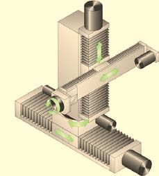
Motorische Präzisionsschlitten Typ PFS Motorized Precision Slides Type PFS
Konstruktionsmerkmale
         Design characteristics

  Die FÖHRENBACH-Präzisionsschlitten Typ PFS wurden           The FÖHRENBACH precision slides type PFS
  entsprechend den Anforderungen des Maschinen-               became constructed corresponding to the requests
  und Sondermaschinenbaus konstruiert.                        of the mechanical and special engineering.
  Durch 5 Baureihen in Breiten von 100 mm bis                 5 series with sizes from 100 mm until 425 mm
  425 mm und Hüben bis zu 2.000 mm können tech-               width and strokes until 2000 mm are available.
  nisch optimale Problemlösungen bei einem guten              Thus technical optimal problem solutions in a good
  Preis-/Leistungsverhältnis realisiert werden.               price-/achievement ratio can be realized.
  Minimaler Einbauraum bei hoher Belastung und                Minimal installation space, high load capacity and
  Steifigkeit zeichnen das Produkt PFS aus.                   stiffness price the product PFS.

Die Profilführungsschlitten (PFS) werden zum Schutz gegen Verschmutzung mit Faltenbälgen abgedeckt.
Andere Abdeckungen auf Anfrage.
To protect them against dirt accumulations, the profiled guide slides (PFS) are covered with bellow covers.
Other covers on request.

  Als Werkstoffe sind Aluminium, natur anodisiert oder         The slides can be manufact from matrials aluminium
  Grauguss GGK-25 lieferbar. Optional Stahl C-45.              (nature anodisiert), or casted iron GGK-25. Optional
  Die Kugelgewindetriebe sind in den Qualitäten T5 und         steel C-45. The ball thread spindle drives are availa-
  T7 bei Spindelsteigungen von 5 bis 50 mm lieferbar.          ble in the qualities T5 and T7 with spindle pitches
  Mehr als 25-jährige Erfahrung im Bau von Präzisions-         from 5 to 50 mm.
  führung und Positioniersystemen sind die Gewähr für          More than 25 years experiance in building precision
  industrieerprobte Produkte, die auch höchsten Bean-          slides and positioning systems are a guarantee for in-
  spruchungen im 3-Schicht-Betrieb standhalten.                dustry proved products, which bear up to the highest
  Nutzen Sie unsere Erfahrung und unser Know-How,              stresses in 3-shift operating.
  zu Ihrem Vorteil.                                            Use our experience and our Know-How to your ad-
                                                               vantage.

                                                          2
Inhalt | Table of Contents
2 Konstruktionsmerkmale/ Design characteristics/
4 Technische Daten Technical data
Typenauswahl Choice of types
Ablauftoleranzen Run-out tolerances
Tragzahlen der Kugelgewindetriebe Loading capacities of ball screw spindle
drive
Momentenbelastbarkeit Torque loading capacity
Torsionssteifigkeiten Torsional stiffnesses
Anforderungen an die Demands to be made on the
Anschlusskonstruktion connecting constructions
8 Systembeschreibung System description
Typ PFS Basisausführung Model PFS (basic equipment)
9 PFS 100 PFS 100
10 PFS 155 PFS 155
11 PFS 225 PFS 225
12 PFS 325 PFS 325
13 PFS 425 PFS 425
14 Montagearten für Kreuztische Type of mounting of co-ordinate
Tables
15 Induktive Endschalter Inductive limit switches
16 Auswahl an Motoren Selection of motors
17 Zeichnung für kundenspezifischen Drawing for custom-specific motor mount
Motoranbau
18 Motor-Anbauvarianten Motor mounting options
Motoranbau gerade Direct motor drive
Motoranbau über Motor drive via
Zahnriemenantrieb toothed belt
Motoranbauvarianten mit Motor mounting options with
Zahnriemenantrieb toothed belt
Montageart bei Faltenbalgab- Type of Mounting when bellows covers
deckungen mit Edelstahllamellen with stainless steel lamellas
21 Montagewinkel Mounting brackets
22 Montagewinkel für Hochkantausleger Mounting brackets for upright
extension arm
23 Montagemöglichkeiten Assembling possibilities
25 Messsysteme Measuring systems
Messsysteme Measuring systems
Mechanische Schalter Switches mechanical
26 Schmierung Lubrication
27 Steuerung unipos 120/220/C110 Control system unipos 120/220/C110
28 Steuerung unipos C220 Control system unipos C220
29 Verkaufsbedingungen General terms and conditions of sale
30 Bestellschlüssel Order key
3Technische Daten | Technical Data
Typen-Auswahl
Choice of types
Technische Daten
Technical Data
max. Vorschubkraft* max. Hub max. Verfahrgeschwindigkeit** Positioniergenauigkeit Wiederholgenauigkeit
max. feed force* max. Stroke max. Traverse rate** Positioning accuracy Repeating accuracy
Aluminium Grauguss
Aluminium Grey cast iron
T7 T5 T7 T5
PFS 100 650 N 1400 N 1600 mm 160 m/min 0,03/300 mm 0,003 mm
PFS 155 2000 N 2600 N 1000 mm 150 m/min 0,06/300 mm 0,03/300 mm 0,005 mm 0,003 mm
PFS 225 2700 N 3200 N 1600 mm 150 m/min 0,06/300 mm 0,03/300 mm 0,005 mm 0,003 mm
PFS 325 3500 N 5600 N 2000 mm 150 m/min 0,06/300 mm 0,03/300 mm 0,005 mm 0,003 mm
PFS 425 5000 N 8000 N 2000 mm 120 m/min 0,06/300 mm 0,03/300 mm 0,005 mm 0,003 mm
mit Linearencoder / with linear encoder*** ***0,002 mm ***0,001 mm
*** Höhere Vorschubkräfte auf Anfrage | higher feed forces on request
*** bei maximaler Steigung und max. Drehzahl | at maximum lead and maximum rpm
*** siehe auch Seite 25 | see also page 25
Ablauftoleranzen
Run-out Tolerances
A B
Ablauftoleranz A [µm] | run-out tolerance A [µm]
40
m – Quality S
30 erial aluminiu
inium – Qualität S | Mat
Werkstoff Alum
20 Quality S
lität S | Material GGK-25 –
Werkstoff GGK-25 – Qua
10 Werkstoff GGK-25 – Qualität P | Material GGK-25 – Quality
P
Hub [mm]
0
500 1000 1500 2000 Stroke [mm]
[mm]
Ablauftoleranz B [µm] | run-out tolerance B [µm]
40 – Qualit
yS
te rial aluminium
ät S | Ma
30 – Qualit
toff Aluminium
Werks
20 yS
ial GGK-25 – Qualit
– Qualität S | Mater
Werkstoff GGK-25
10 25 – Quality P
Werkstoff GGK-25 – Qualität P | Material GGK-
Stroke
Hub [mm]
[mm]
0
500 1000 1500 2000 Stroke[mm]
[mm]
4Technische Daten | Technical Data
Tragzahlen der Kugelgewindetriebe Diagramm für kritische Drehzahlen
Loading capacities of ball screw spindle drive Critical speeds diagram
(nur zur Lebensdauerberechnung) | (only for lifetime calculation)
Schlittenlänge L [mm] (≈ Spindellänge)
Typ Spindel Length of slide L [mm] ( ≈ length of spindle)
C dyn. N C stat. N
Type Spindle
3000
PFS 100 K 12 x 5 3800 4.500
K 12 x 10 4400 4.800
PFS 155/225 K 20 x 5 20000 34.000 2000
K 20 x 10 13000 20.000
K 20 x 20 11600 18.400
K 20 x 50 13000 24.600
PFS 325 K 25 x 5 18000 33.000
K 25 x 10 14000 24.000 Ø=32
K 25 x 20 13000 23.300 1000 Ø=25
K 25 x 50 15400 31.700 Ø=20
PFS 425 K 32 x 5 25000 53.000
K 32 x 10 60000 100.000 Ø=12
K 32 x 20 39000 59.000
K 32 x 40 14900 32.400 kritische
Drehzahl [min–1] |
Dynam. Tragzahl nach DIN 69051 Teil 4 Entwurf 1979 | 500
critical speed
Dynamic load capacity according to DIN69051. part 4, draft 1979 500 1000 2000 3000 [min–1]
Zulässige max. Spindeldrehzahl
= kritische Drehzahl x 0,8 [min-1]
Lagertragzahlen | Bearing load capacities
max. permissible spindle r.p.m.
(Festlager) | (Fixed locating bearing)
= critical speed r.p.m. x 0.8 [min-1]
Typ axial C dyn. axial Co
PFS 100 8,1 kN 4 kN
PFS 155 17,9 kN 28 kN
PFS 225 17,9 kN 28 kN
PFS 325 18,8 kN 31 kN
PFS 425 26,0 kN 47 kN
100
Zulässige axiale Spindelbelastung (Knickung)
Admissible axial load (buckling)
F [kN]
50
Die zulässige axiale Spindelbelastung The maximum admissible spindle
ist abhängig von Spindeldurchmesser, load depends on the related spindle 40
Einbauart und der nicht gestützten Länge diameter, the type of installation and 30
the not-supported length.
Die im Diagramm angegebenen Werte
20
wurden mit Sicherheitsfaktor 2 errech- The values indicated in the diagram
net. were calculated with a safety factor 2.
10
Ø 32
5
4
3 Ø 25
2
Ø 20
1
Ø 12
0
0 0,2 0,3 0,4 0,5 1 2 3
Länge l [m] | Length l [m]
5Technische Daten | Technical Data
Tragzahlen
Loading capacities
Berechnung der Lebensdauer der Formula of calculation for the lifetime
➠ Führung: of the guide rail:
Cdyn 3 Cdyn 3
L= ·105 L= ·105
➠
F1 F F
Lh = L Lh = L
60 · vm 60 · vm
➠ ➠
F2 F2
L = nominelle Lebensdauer (m) L = nominal working life (m)
Lh = nominelle Lebensdauer (h) Lh = nominal working life (h)
Cdyn = dynamische Tragzahl (N) Cdyn = dynamic load capacity (N)
F = äquivalente Belastung (N) F = equivalent load (N)
vm = mittlere Geschwindigkeit (m/min) vm = mean speed (m/min)
Größe x Verschiebeteillänge C dyn C 0 F1 C 0 F2
Size x Length of shifting element F1/F2 [kN] [kN] [kN] Faktoren die
die Lebensdauer mindern:
kurzes Ver- PFS 100 x 100 17,7 26,5 13 Factors reducing the working life:
<
schiebeteil PFS 155 x 155 25,5 44 22
PFS 225 x 225 74,7 99 49 Verschmutzung der Führungssysteme
short shif-
PFS 325 x 325 103 135 67 Unzureichende Schmierung
ting element
PFS 425 x 425 137 177 88 Sehr kleine Hübe
Vibrationen bei Stillstand
PFS 100 x 150 25,5 44 22 Überlastung der Führung
langes Ver-
schiebeteil PFS 155 x 225 33,6 58 29
PFS 225 x 335 98,4 131 65 dirt accumulation in the guid systemes
long shifting PFS 325 x 540 136 178 89 insufficient lubrication
element PFS 425 x 700 181 233 116 very short strokes
vibrations at standstill
guide overload
Momentenbelastbarkeit
Torque loading capacity
MX MY MZ
Größe x Verschiebeteillänge Mx (dyn.) Mxo My (dyn.) Myo Mz (dyn.) Mzo
Size x Length of shifting element [Nm] [Nm] [Nm] [Nm] [Nm] [Nm]
kurzes Ver- PFS 100 x 100 443 664 478 717 443 332
schiebeteil PFS 155 x 155 993 1718 1279 2214 993 854
PFS 225 x 225 4487 5983 5048 6731 4487 2940
short shif- PFS 325 x 325 9930 12937 10658 13885 9930 6399
ting element
PFS 425 x 425 18553 23911 17935 23114 18553 11880
langes Ver- PFS 100 x 150 1023 1771 691 1196 1023 880
schiebeteil PFS 155 x 225 1791 3100 1685 2916 1791 2030
long shifting PFS 225 x 335 8974 11965 6648 8865 8974 7800
element PFS 325 x 540 21575 28109 14037 18288 21575 18468
PFS 425 x 700 36832 47468 23622 30443 36832 31088
6Technische Daten | Technical Data
Torsionssteifigkeit
Torsion stiffness
Torsionssteifigkeit KT [Nm/°] Werkstoff: Al: EN AW-6060 T6/EN AW-6082 Werkstoff: GGK-P-25
Torsional stiffness Material: aluminium Material: cast iron
Größe x Verschiebeteillänge
Mx [Nm/°] My [Nm/°] Mz [Nm/°] Mx [Nm/°] My [Nm/°] Mz [Nm/°]
Size x Length of shifting element
kurzes Ver- PFS 100 x 100 1.795 1.939 3.103 2.693 2.908 4.654
schiebeteil PFS 155 x 155 9.850 12.693 11.211 14.775 19.040 16.816
PFS 225 x 225 30.600 34.425 41.888 45.900 51.637 62.832
short shif-
PFS 325 x 325 75.932 81.497 132.649 113.897 122.246 198.973
ting element
PFS 425 x 425 187.899 161.056 402.745 281.849 241.585 604.117
langes Ver- PFS 100 x 150 5.386 2.908 12.411 8.078 4.362 18.617
schiebeteil PFS 155 x 225 26.656 19.040 36.489 39.984 28.560 54.734
PFS 225 x 335 91.800 51.637 167.552 137.700 77.456 251.327
long shifting PFS 325 x 540 247.473 122.246 626.228 371.210 183.369 939.342
element PFS 425 x 700 527.907 241.585 1.412.905 791.860 362.377 2.119.357
Berechnung: Verdrehwinkel = Moment ÷ Torsionssteifigkeit M
α=
KT
Calculation: angle = torque ÷ torsional stiffness
Anforderungen an die Anschlusskonstruktion
Requirements to the connecting construction
Um die angegebene Genauigkeit und Steifigkeit erreichen To achieve and to ensure the indicated accuracy and rigidity the
zu können, müssen folgende Voraussetzungen erfüllt sein: following requirements need to be met:
Die Ebenheit muss bei ca. 50% der erwarteten Genauigkeit The evenness must be approx. 50% of the expected accuracy.
liegen. The surface of the connecting construction must be at least as
Die Oberfläche der Anschlusskonstruktion muss mindestens indicated in picture below
die Ebenheit wie im Bild haben. The connecting construction must be at least of thickness E.
Die Anschlusskonstruktion muss mind. die Dicke E haben. The material used must be at least equivalent to the rigidity of
Der Werkstoff der Anschlusskonstruktion muss mindestens the material used for the slides (or have a higher E module).
die Steifigkeit des Schlittenmaterials haben (oder höherer All threads in the base plate must be used.
Elastizitätsmodul E).
At least the two inner drill hole lines provided in the sliding element
Alle Anschraubmöglichkeiten der Grundplatte müssen ver- must bee fastened with screws.
wendet werden.
Es müssen mind. die zwei inneren Bohrreihen des Verschiebe-
teils verschraubt werden.
E [mm]
E
PFS 100 15
T
T/200 PFS 155 20
PFS 225 30
PFS 325 35
PFS 425 45
T/200
T/200
T
T = 0.01 bei Werkstoff GGK-25 | Material: GGK-25
T = 0.03 bei Werkstoff Al | Material: aluminium
E
7Systembeschreibung | System Description
Typ PFS (Basisausführung)
Model PFS (basic equipment)
Basisausführung Optionen Options
Kugelgewindetrieb Die Faltenbalgdeckungen können optional mit On option, the bellows covers can be equipped with
gem. Standardzuordnung (siehe S. 5) Edelstahllamellen ausgerüstet werden. stainless steel lamellas to protect them effectively
verschraubte Faltenbalgabdeckung Hierdurch wird ein wirkungsvoller Schutz gegen against any hot or sharp-edged elements and
beidseitig beschichtet heiße und scharfkantige Gegenstände (z.B. beim components (e.g. lasers, welding heads etc.).
eingebaute induktive Endschalter Lasern, Schweißen, ...) erreicht. Such stainless steel lamellas also prevent dirt from
(PNP-Öffner) mit Steckeranschluss in der End- Ebenso wird eine Schmutzansammlung in den accumulating in the bellows. When applying stain-
platte Falten vermieden. less steel lamellas, the actual stroke is reduced ac-
Grundplatte, Verschiebeteil und Endplatte Durch Edelstahllamellen wird der tatsächliche Hub cording to table pages 9 - 13.
Werkstoff: Aluminium natur anodisiert gemäss Tabelle Seiten 9 - 13 reduziert.
Grauguss GGK-25 blank
Profilführungsschienen
Führungswagen
Kurzes Verschiebeteil mit 4 Führungswagen
oder langes Verschiebeteil mit 6 Führungswagen
Motorflansch aus Aluminium natur anodisiert
Basic equipment
ball screw spindle acc. to standard type
allocation (see page 5)
screwed up bellows cover coated on both
• sides
integrated inductive limit switches
• (PNP break contact) incl. plug-connector in
• the endplate
base plate, sliding element and endplate:
material: aluminium natural anodised grey Einbauvarianten
cast iron GGK-25, bare Endschalter: siehe S. 15
guide rails
rail guided carriage Limit switch installation
short sliding element with 4 rail guided carria- variants: see page 15
ges or long sliding element with 6 carriages
Motor flange of anodised natural aluminium
B2
Seitenabdeckbleche
Lateral cover sheets
Typ Abmessungen [mm] L8
Type Dimensions [mm]
Seitenabdeckbleche (optional) empfohlen
L H B bei Hochkant- und MU-Montage
8 2
gem. Bild unten.
PFS 100 L*-20 48 2
PFS 155 L*-40 55 2
Lateral cover sheets (on option) recom-
PFS 225 L*-40 80 2
mended for type of top edge mounting
PFS 325 L*-60 100 2
PFS 425 L*-60 120 2 and type of mounting MU according to
H
picture.
L* Gesamtlänge der Positioniereinheit (siehe Baugröße
PFS 100 bis PFS 425)
L* Total overall length of the positioning untit (see size
PFS 100 to PFS 425)
Alle Schlitten werden mit Passbohrungen in den
Verschiebeteilen ausgeliefert, womit Anbauteile parallel
zur Führungsrichtung ausgerichtet werden können.
Hierfür können gehärtete Bohrbuchsen nach DIN 179A
verwendet werden.
All slides are delivered with exactly matching drill holes
provided in the sliding elements, which enable to adjust
attachments and built-on accessories exactly parallel to
the related guiding direction. For this purpose, hardened
DIN 179A compliant drill bushes must be used.
Motoranbauvarianten siehe S. 18 - 20
Various types of motor attachments see page 18 - 20
8PFS 100
Baugröße PFS 100 86
Dimension for PFS 100
24
b
L H u r ok e
St Ø3
36 Ø3 2 H
2 H 7- 2
7- ti e
2d f
L6 ee
20
p
86 M4-6tief
X·
27
L2 29
50
Grundplattensenkung
10 countersink Ø8
0 Ø10 h
7
,5
23
14
8,3
In der Grundplatte sind mittig vier Bohrungen
für die Montageart MN vorhanden.
Ø5,5
In the base plate centrically four drillings for
mounting type MN are present.
Abmessungen (mm) und Gewicht (kg) bei kurzem Verschiebeteil
Dimensions (mm) and weight (kg) with short sliding element
Hub red. Hub*
L2 Gewicht Gewicht
Stroke red. Stroke*
L L red. Hub* L X·86 Weight Weight
2 6
red. Stroke* AL GG
Mech. Hub: + 20 + 20
Mech Stroke
50 40 260 57,5 62,5 44 2 3,4 5,4
100 85 320 62,5 70 74 2 3,8 6,1
150 130 380 67,5 77,5 61 3 4,2 6,9
200 170 440 72,5 87,5 48 4 4,6 7,6
250 215 500 77,5 95 35 5 5 8,4
300 260 560 82,5 102,5 65 5 5,5 9,1
400 350 685 95 120 41,5 7 6,3 10,6
500 440 805 105 135 58,5 8 7,2 12,1
600 530 930 117,5 152,5 35 10 8 13,7
* Faltenbalg mit Edelstahllamellen · * Bellows covers with stainless steel lamellas
Motoranbauvarianten mit Edelstahllamellen siehe Seite 20 · Motor drive with stainless steel lamellas page 20
Bewegte Masse: Moved mass:
Alu-Verschiebeteil = 0,92 kg Sliding element of aluminium = 0,92 kg
Guss-Verschiebeteil = 1,57 kg Cast sliding element = 1,57 kg
Abmessungen (mm) und Gewicht (kg) bei langem Verschiebeteil
Dimensions (mm) and weight (kg) with long sliding element
Hub red. Hub*
L2 Gewicht Gewicht
Stroke red. Stroke*
L L red. Hub* L X·86 Weight Weight
2 6
red. Stroke* AL GG
Mech. Hub:
Mech Stroke + 20 + 20
50 40 320 62,5 67,5 74 2 4,2 6,9
100 85 380 67,5 75 61 3 4,6 7,6
150 130 440 72,5 82,5 48 4 5 8,4
200 170 500 77,5 92,5 35 5 5,5 9,1
250 215 560 82,5 100 65 5 5,9 9,9
300 260 610 82,5 102,5 47 6 6,2 10,5
400 350 735 95 120 66,5 7 7,1 12
500 440 855 105 135 40,5 9 7,9 13,5
600 530 980 117,5 152,5 60 10 8,8 15,1
* Faltenbalg mit Edelstahllamellen · * Bellows covers with stainless steel lamellas
Motoranbauvarianten mit Edelstahllamellen siehe Seite 20 · Motor drive with stainless steel lamellas page 20
Bewegte Masse: Moved mass:
Alu-Verschiebeteil = 1,35 kg Sliding element of aluminium = 1,35 kg
Guss-Verschiebeteil = 2,33 kg Cast sliding element = 2,33 kg
9PFS 155
13
Baugröße PFS 155 0
Dimension for PFS 155 32
b
H u ok e
L r
St Ø4
60 Ø4 6 H
6 H 7 -2
7 - ,5
2 , 5 t ie
L6 de f
30
ep
0 M6-9 tief (4x)
13
X·
33
L2 39
60
Grundplattensenkung
15 countersink Ø1
5 Ø11 2h
7
33
20
13,2
In der Grundplatte sind mittig vier Bohrungen Ø6,6
für die Montageart MN vorhanden.
In the base plate centrically four drillings for
mounting type MN are present.
Abmessungen (mm) und Gewicht (kg) bei kurzem Verschiebeteil
Dimensions (mm) and weight (kg) with short sliding element
Hub red. Hub*
L2 Gewicht Gewicht
L L red. Hub* L X·130 Weight Weight
Stroke red. Stroke* 2 6
red. Stroke* AL GG
Mech. Hub: + 20 + 20
Mech Stroke
50 40 335 68,5 73,5 102,5 1 7,2 14,4
100 85 405 78,5 86 72,5 2 8,1 16,3
150 130 470 86 96 105 2 9,1 18
200 175 530 91 103,5 70 3 9,9 19,6
300 270 640 96 111 60 4 11,5 22,5
400 360 760 106 126 55 5 13,2 25,7
,
500 450 880 116 141 50 6 14,9 28,9
600 540 1005 128,5 158,5 47,5 7 16,7 32,2
800 720 1250 151 191 105 8 20,2 38,7
1000 900 1495 173,5 223,5 97,5 10 23,7 45,2
* Faltenbalg mit Edelstahllamellen · * Bellows covers with stainless steel lamellas
Motoranbauvarianten mit Edelstahllamellen siehe Seite 20 · Motor drive with stainless steel lamellas page 20
Bewegte Masse: Moved mass:
Alu-Verschiebeteil = 2,64 kg Sliding element of aluminium = 2,64 kg
Guss-Verschiebeteil = 5,59 kg Cast sliding element = 5,59 kg
Abmessungen (mm) und Gewicht (kg) bei langem Verschiebeteil
Dimensions (mm) and weight (kg) with long sliding element
Hub red. Hub*
L2 Gewicht Gewicht
L L red. Hub* L X·130 Weight Weight
Stroke red. Stroke* 2 6
red. Stroke* AL GG
Mech. Hub:
Mech Stroke + 20 + 20
50 40 405 68,5 73,5 72,5 2 9,3 18,9
100 85 470 76 83,5 105 2 10,3 20,6
150 130 530 81 91 70 3 11,1 22,2
200 175 590 86 98,5 100 3 12 23,8
300 270 710 96 111 95 4 13,7 27
400 360 830 106 126 90 5 15,4 30,2
,
500 450 950 116 141 85 6 17 33,4
600 540 1075 128,5 158,5 82,5 7 18,9 36,7
800 720 1320 151 191 75 9 22,4 43,2
1000 900 1565 173,5 223,5 67,5 11 25,9 49,7
* Faltenbalg mit Edelstahllamellen · * Bellows covers with stainless steel lamellas
Motoranbauvarianten mit Edelstahllamellen siehe Seite 20 · Motor drive with stainless steel lamellas page 20
Bewegte Masse: Moved mass:
Alu-Verschiebeteil = 3,8 kg Sliding element of aluminium = 3,8 kg
Guss-Verschiebeteil = 8,24 kg Cast sliding element = 8,24 kg
10PFS 225
18
0
Baugröße PFS 225
Dimension for PFS 225 32
b
H u ok e Ø5
r
L St Ø5 5 H
60 5 H 7-2
7- ,5
2,5 tie
de f
L6 ep
30
0 M6-9 tief (4x)
18
X·
50
L2
39
90
Grundplattensenkung
22 countersink Ø1
5 Ø15 2h
7
33
19
10
In der Grundplatte sind mittig vier Bohrungen Ø9
für die Montageart MN vorhanden.
In the base plate centrically four drillings for
mounting type MN are present.
Abmessungen (mm) und Gewicht (kg) bei kurzem Verschiebeteil
Dimensions (mm) and weight (kg) with short sliding element
Hub red. Hub*
L2 Gewicht Gewicht
L L red. Hub* L X·180 Weight Weight
Stroke red. Stroke* 2 6
red. Stroke* AL GG
Mech. Hub:
Mech Stroke + 30 + 30
100 70 460 71 86 50 2 23 46,6
200 160 570 76 96 105 2 25,7 52,5
300 250 685 83,5 108,5 72,5 3 28,6 58,6
400 340 795 88,5 118,5 127,5 3 31,4 64,5
500 430 905 93,5 128,5 92,5 4 34,1 70,4
600 520 1020 101 141 60 5 37 76,5
,
800 700 1245 113,5 163,5 82,5 6 42,6 88,5
1000 880 1465 123,5 183,5 102,5 7 48,1 100,3
1200 1060 1690 136 206 1255 8 53,7 112,3
1400 1240 1910 146 226 77,5 10 59,2 124
1600 1420 2135 158,5 248,5 11 64,8 136
* Faltenbalg mit Edelstahllamellen · * Bellows covers with stainless steel lamellas
Motoranbauvarianten mit Edelstahllamellen siehe Seite 20 · Motor drive with stainless steel lamellas page 20
Bewegte Masse: Moved mass:
Alu-Verschiebeteil = 9,3 kg Sliding element of aluminium = 9,3 kg
Guss-Verschiebeteil = 20,2 kg Cast sliding element = 20,2 kg
Abmessungen (mm) und Gewicht (kg) bei langem Verschiebeteil
Dimensions (mm) and weight (kg) with long sliding element
Hub red. Hub*
L2 Gewicht Gewicht
L L red. Hub* L X·180 Weight Weight
Stroke red. Stroke* 2 6
red. Stroke* AL GG
Mech. Hub:
Mech Stroke + 30 + 30
100 70 570 71 86 105 2 30,3 62,5
200 160 685 78,5 98,5 72,5 3 33,2 68,6
300 250 795 83,5 108,5 127,5 3 35,9 74,5
400 340 905 88,5 118,5 92,5 4 38,7 80,4
500 430 1020 96 131 60 5 41,5 86,4
600 520 1130 101 141 115 5 44,3 92,4
,
800 700 1355 113,5 163,5 47,5 7 49,9 104,4
1000 880 1575 123,5 183,5 67,5 8 55,4 116,2
1200 1060 1800 136 206 90 9 61 128,2
1400 1240 2020 146 226 110 10 66,5 139,9
1600 1420 2245 158,5 248,5 132,5 11 72,2 151,9
* Faltenbalg mit Edelstahllamellen · * Bellows covers with stainless steel lamellas
Motoranbauvarianten mit Edelstahllamellen siehe Seite 20 · Motor drive with stainless steel lamellas page 20
Bewegte Masse: Moved mass:
Alu-Verschiebeteil = 13,8 kg Sliding element of aluminium = 13,8 kg
Guss-Verschiebeteil = 30,2 kg Cast sliding element = 30,2 kg
11PFS 325
26
0
45
Baugröße PFS 325
Dimension for PFS 325
b
H u ok e
r Ø6
L St
65 Ø6 0 H
0 H 7 -3
7- tie
3d f
L6 ee
p
40
0
26
X·
60
L2 5 M6-9 tief (4x)
4
110
Grundplattensenkung
32 countersink Ø1
5 Ø18 5h
7
34
25
14
Ø11
In der Grundplatte sind mittig vier Bohrungen
für die Montageart MN vorhanden.
In the base plate centrically four drillings for
mounting type MN are present.
Abmessungen (mm) und Gewicht (kg) bei kurzem Verschiebeteil
Dimensions (mm) and weight (kg) with short sliding element
Hub red. Hub*
L2 Gewicht Gewicht
L L red. Hub* L X·260 Weight Weight
Stroke red. Stroke* 2 6
red. Stroke* AL GG
Mech. Hub: + 30 + 30
Mech Stroke
100 80 600 87,5 97,5 170 1 51,3 111
200 175 705 90 102,5 92,5 2 55,9 121,1
300 265 815 95 112,5 147,5 2 60,6 131,7
400 360 930 102,5 122,5 75 3 65,6 142,8
500 450 1040 107,5 132,5 130 3 70,4 153,4
600 540 1155 115 145 57,5 4 75,4 164,5
700 635 1265 120 152,5 112,5 4 80,1 175,1
,
800 725 1375 125 162,5 167,5 4 84,9 185,8
1000 910 1600 137,5 182,5 150 5 94,6 207,5
1200 1095 1825 150 202,5 132,5 6 104,4 229,2
1500 1370 2155 165 230 167,5 7 118,7 261
1600 1460 2265 170 240 92,5 8 123,5 315
2000 1830 2715 195 280 57,5 10 143 315,1
* Faltenbalg mit Edelstahllamellen · * bellows covers with stainless steel lamellas
Motoranbauvarianten mit Edelstahllamellen siehe Seite 20 · Motor drive with stainless steel lamellas see page 20
Bewegte Masse: Moved mass:
Alu-Verschiebeteil = 20,2 kg Sliding element of aluminium = 20,2 kg
Guss-Verschiebeteil =48,1 kg Cast sliding element = 48,1 kg
Abmessungen (mm) und Gewicht (kg) bei langem Verschiebeteil
Dimensions (mm) and weight (kg) with long sliding element
Hub red. Hub*
L2 Gewicht Gewicht
L L red. Hub* L X·260 Weight Weight
Stroke red. Stroke* 2 6
red. Stroke* AL GG
Mech. Hub:
Mech Stroke + 30 + 30
100 80 815 87,5 97,5 147,5 2 73,2 163,1
200 175 930 95 107,5 75 3 78,2 174,2
300 265 1040 100 117,5 130 3 83 184,8
400 360 1155 107,5 127,5 57,5 4 87,9 195,9
500 450 1265 112,5 137,5 112,5 4 92,7 206,5
600 540 1375 117,5 147,5 167,5 4 97,5 217,2
700 635 1480 120 152,5 90 5 102 227,3
,
800 725 1600 130 167,5 150 5 107,2 238,9
1000 910 1825 142,5 187,5 132,5 6 117 260,6
1200 1095 2040 150 202,5 110 7 126,3 281,3
1500 1370 2370 165 230 145 8 140,6 313,1
1600 1460 2480 170 240 70 9 145,4 323,7
2000 1830 2930 195 280 165 10 164,9 367,1
* Faltenbalg mit Edelstahllamellen · * bellows covers with stainless steel lamellas
Motoranbauvarianten mit Edelstahllamellen siehe Seite 20 · Motor drive with stainless steel lamellas see page 20
Bewegte Masse: Moved mass:
Alu-Verschiebeteil = 32,8 kg Sliding element of aluminium = 32,8 kg
Guss-Verschiebeteil = 79,5 kg Cast sliding element = 79,5 kg
12PFS 425
34
0
Baugröße PFS 425
Dimension for PFS 425 45
b
H u ok e
r Ø6
L St
65 Ø6 0 H
0 H 7 -3
7- tie
3d f
L6 ee M6-9 tief (4x)
p
40
0
34
X·
70
L2 5
4
130
Grundplattensenkung
42 countersink Ø1
5 Ø20 7h
7
34
25
12
In der Grundplatte sind mittig vier Bohrungen Ø13,5
für die Montageart MN vorhanden.
In the base plate centrically four drillings for
mounting type MN are present.
Abmessungen (mm) und Gewicht (kg) bei kurzem Verschiebeteil
Dimensions (mm) and weight (kg) with short sliding element
Hub red. Hub*
L2 Gewicht Gewicht
L L red. Hub* L X·340 Weight Weight
Stroke red. Stroke* 2 6
red. Stroke* AL GG
Mech. Hub:
Mech Stroke + 30 + 30
200 170 800 87,5 102,5 60 2 116 239
300 265 915 95 112,5 117,5 2 123 254,5
400 365 1025 100 117,5 172,5 2 130 270
500 460 1135 105 125 57,5 3 136,9 285,3
600 560 1245 110 130 112,5 3 143,7 300,3
800 755 1460 117,5 140 220 3 157,1 329,9
1000 950 1680 127,5 152,5 160 4 170,8 360,2
,
1200 1145 1900 137,5 165 100 5 184,5 390,5
1500 1435 2230 152,5 185 95 6 205,1 435,9
1600 1530 2335 155 190 147,5 6 211,8 450,4
2000 1920 2775 175 215 197,5 7 239 511
* Faltenbalg mit Edelstahllamellen · * bellows covers with stainless steel lamellas
Motoranbauvarianten mit Edelstahllamellen siehe Seite 20 · Motor drive with stainless steel lamellas see page 20
Bewegte Masse: Moved mass:
Alu-Verschiebeteil = 41,3 kg Sliding element of aluminium = 41,3 kg
Guss-Verschiebeteil = 104 kg Cast sliding element = 104 kg
Abmessungen (mm) und Gewicht (kg) bei langem Verschiebeteil
Dimensions (mm) and weight (kg) with long sliding element
Hub red. Hub*
L2 Gewicht Gewicht
L L red. Hub* L X·340 Weight Weight
Stroke red. Stroke* 2 6
red. Stroke* AL GG
Mech. Hub:
Mech Stroke + 30 + 30
200 170 1075 87,5 102,5 197,5 2 158,3 343,9
300 265 1190 95 112,5 85 3 165,3 359,4
400 365 1300 100 117,5 140 3 172,3 374,9
500 460 1410 105 125 195 3 179,2 390,2
600 560 1520 110 130 80 4 186 405,2
800 755 1735 117,5 140 187,5 4 199,4 343,8
1000 950 1955 127,5 152,5 127,5 5 213,1 465,1
,
1200 1145 2175 137,5 165 67,5 6 226,8 495,4
1500 1435 2505 152,5 185 62,5 7 247,4 540,8
1600 1530 2610 155 190 115 7 253,9 555,3
2000 1920 3050 175 215 165 8 281,3 615,9
* Faltenbalg mit Edelstahllamellen · * bellows covers with stainless steel lamellas
Motoranbauvarianten mit Edelstahllamellen siehe Seite 20 · Motor drive with stainless steel lamellas see page 20
Bewegte Masse: Moved mass:
Alu-Verschiebeteil = 66,5 kg Sliding element of aluminium = 66,5 kg
Guss-Verschiebeteil = 171 kg Cast sliding element = 171 kg
13Montagearten für Kreuztische |
Type of Mounting for Co-ordinate Tables
Montagearten für Kreuztische
Type of mounting for co-ordinate tables
Montageart MN... Montageart MU...
Type of mounting MN... Type of mounting MU...
Z
X Y
Die Grundplatte der Y-Achse ist auf dem Schlitten der X-Achse montiert. Die Schlitten der Y-Achse ist auf dem Schlitten der X-Achse montiert (Sonder-
– X-Achse: Grundplatte fest, Schlitten beweglich ausführung).
– Y-Achse: Grundplatte fest, Schlitten beweglich – X-Achse: Grundplatte fest, Schlitten beweglich
The base plate of the Y axis is mounted on top of the X axis slide. – Y-Achse: Schlitten fest, Grundplatte beweglich
– X axis: base plate fixed, slide movable The slide of the Y axis is mounted on top of the X axis slide (special design).
– Y axis: base plate fixed, slide movable – X axis: base plate fixed, slide movable
– Y axis: slide fixed, base plate movable
Empfohlene maximale Hübe der oberen Achse bei Koordinatentischen
Recommennded maximum strokes of the upper axis for coordinate tables
Montageart MN | Type of mounting MN
Werkstoff: GGK-25 Werkstoff: Aluminium
Material: Cast iron GGK-25 Material: Aluminium
Typ Hub Steifigkeit Durchbiegung* Steifigkeit Durchbiegung*
Type Stroke Stiffness Deflection* Stiffness Deflection*
[mm] [N/µm] f [µm] [N/µm] f [µm]
PFS 100 300 0,015 0,4 0,017 0,2
PFS 155 400 0,020 3,6 0,024 3,0
PFS 225 600 0,083 24,8 0,057 16,2
PFS 325 800 0,012 18,8 0,015 9,6
PFS 425 1000 0,012 37,4 0,014 18,2
* ohne Belastung | without load
Montageart MU | Type of mounting MU
Werkstoff: GGK-25 Werkstoff: Aluminium
Material: Cast iron GGK-25 Material: Aluminium
Typ Hub Steifigkeit Durchbiegung* Steifigkeit Durchbiegung*
Type Stroke Stiffness Deflection* Stiffness Deflection*
[mm] [N/µm] f [µm] [N/µm] f [µm]
PFS 100 300 1,25 51 1,11 32
PFS 155 400 1,11 178 0,95 111
PFS 225 600 0,83 683 0,56 476
PFS 325 800 2,50 580 2,08 312
PFS 425 1000 2,56 1022 2,13 551 B = Baugröße | B = size
* ohne Belastung | without load
Rechtsmontage ...R Linksmontage ...L Rechtsmontage ...R Linksmontage ...L
Right hand mounting ...R Left hand mounting ...L Right hand mounting ...R Left hand mounting ...L
X-Achse unten Y-Achse oben X-Achse unten Y-Achse oben X-Achse unten Y-Achse oben X-Achse unten Y-Achse oben
X axis below Y axis on top X axis below Y axis on top X axis below Y axis on top X axis below Y axis on top
Bestell-Code bei Rechtsmontage: MNR Bestell-Code bei Rechtsmontage: MUR
Bestell-Code bei Linksmontage: MNL Bestell-Code bei Linksmontage: MUL
Code for ordering right hand mounting: MNR Code for ordering right hand mounting: MUR
Code for ordering left hand mounting: MNL Code for ordering left hand mounting: MUL
14Induktive Endschalter | Inductive Limit Switches
Einbauvarianten / Abmessungen induktive Endschalter, Standard PNP-Öffner
Options for installations / Dimensions of induktive limit switches
komplett verdrahtet auf Flanschstecker: Binder Typ Serie 712, 5-polig
complete with wiring to flanged plugs: Binder type series 712, 5-contacts Referenzpunkt
Laufrichtung
Steckerbelegung:
A = Standard
Allocation of plug terminals:
Refernce point
1 = Endschalter Richtung A / limit switches direction A
direction of travel
2=0V
A = Standard
3 = Endschalter Richtung B / limit switches direction B
4 = 24 V
5 = Referenz / reference
Einbauvariante 0, 1 / Installation Type 0, 1
2 induktive Endschalter innen
2 internal inductive end of travel limit switches
sw br
sw = schwarz / black
br = braun / brown br
bl = blau / blue
3 2
4 bl
bl
sw
5 1
+ Richtung
+ direction
Standard:
Schalter A = Referenzschalter Endschalter Richtung B Endschalter Richtung A
(Brücke von 5 auf 1) limit switches direction B limit switches direction A
Einbauvariante 2, 4, 6, 8 Laufrichtung A / Installation Type 2, 4, 6, 8 direction of travel A
2 induktive Endschalter innen + 1 Referenzpunktschalter
2 internal inductive end of travel limit switches + 1 reference
point switch
sw br
sw = schwarz / black br
br = braun / brown 3
2
bl = blau / blue bl
bl 4
sw
5 1
bl
sw
br
Endschalter Richtung B Endschalter Richtung A
limit switches direction B limit switches direction A
Referenzpunkt
reference point
Einbauvariante 3, 5, 7, 9 Laufrichtung B / Installation Type 3, 5, 7, 9 Direction of travel B
2 induktive Endschalter innen + 1 Referenzpunktschalter
2 internal inductive end of travel limit switches + 1 reference
point switch
sw br
sw = schwarz / black
br
br = braun / brown
3
bl = blau / blue 2
4
bl
bl sw
5 1
bl
sw
br
Endschalter Richtung B Endschalter Richtung A
limit switches direction B limit switches direction A
Referenzpunkt
reference point
15Auswahl an Motoren | Selection of Motors
Motoranbau: direkt Motoranbau: über Riementrieb Motortyp Bestell-Code
Motor mounting: direct Motor mounting: via toothed belt Motor type Ordering code
Typ Schrittmotor Servomotor Schrittmotor Servomotor
Type Stepper Motor Servo Motor Stepper Motor Servo Motor SW 57 02
SM 57 45
PFS 100 SW 57 ABR 55, Typ 1 SW 57 ABR 55 Typ 1 SM 86 15
SM 57 ASR 58 Typ 1 SM 57 ASR 58 Typ 1 SB 57 45
SB 86 ABR 70 Typ 1 SM 86 ABR 70 Typ 1 SB 85 14
SB 57 SB 57 ABR 55 Typ 1 10
SB 85* SB 85* ABR 55 Typ 2 28
ASR 58 Typ 1 87
PFS 155 SM 86 ABR 55 Typ 2 SM 86 ABR 55 Typ 2
ASR 58 Typ 2 28
SB 85 ASR 58 Typ 1 SB 85 ASR 58 Typ 1
ASR 58 Typ 2 ASR 58 Typ 2 ABR 70 Typ 1 18
ABR 70 Typ 1 ABR 70 Typ 1 ABR 70 Typ 2 93
ABR 70 Typ 2 ABR 70 Typ 2 ASR 70 Typ 1 56
ASR 70 Typ 1 ASR 70 Typ 1 ASR 70 Typ 2 93
ASR 70 Typ 2 ASR 70 Typ 2 ASR 84 Typ 1 29
ASR 84 Typ 2 92
PFS 225 SM 86 ABR 70 Typ 1 SM 86 ABR 70 Typ 1 ABR 92 Typ 1 38
SB 85 ABR 70 Typ 2 SB 85 ABR 70 Typ 2 ABR 92 Typ 2 92
ASR 70 Typ 1 ASR 70 Typ 1 ABR 11 Typ 1 53
ASR 70 Typ 2 ASR 70 Typ 2 ABR 11 Typ 2 92
ASR 84 Typ 1 ASR 84 Typ 1
ASR 11 Typ 1 53
ASR 84 Typ 2 ABR 92 Typ 1
ASR 11 Typ 2 92
ABR 92 Typ 1
ABR 92 Typ 2
PFS 325/425 ASR 84 Typ 1 ASR 84 Typ 1
ASR 84 Typ 2 ASR 84 Typ 2
ABR 92 Typ 1 ABR 92 Typ 1
ABR 92 Typ 2 ABR 92 Typ 2
ABR 11 Typ 1 ABR 11 Typ 1
ABR 11 Typ 2 ABR 11 Typ 2
ASR 11 Typ 1 ASR 11 Typ 1
ASR 11 Typ 2 ASR 11 Typ 2
Typ 1: ohne Getriebe Type 1: without gear
Typ 2: mit Getriebe Type 2: with gear
* Nur Motorwellen Ø 9,5 mm | Only motor shaft Ø 9.5 mm
Der Anbau von Fremdmotoren ist möglich (Bitte Blatt “Motor-Anbauvarianten …“ ausfüllen). Andere Motoren auf Anfrage
The use of customers’ free issue motors is possible (Please add datasheet from motor). Other motors on request
Maximales Lastmoment | Max. loadmoment
berechnet aus max. Vorschubkraft | calculated from max. feed force
Werkstoff Typ Steigung | Gradient
Material Type 5 mm 10 mm 20 mm 40 mm 50 mm
M [Nm] M [Nm] M [Nm] M [Nm] M [Nm]
PFS 100 0,52 1,03
Aluminium PFS 155 1,59 3,18 6,00 6,00
Aluminium PFS 225 2,15 4,30 6,00 6,00
PFS 325 2,79 5,57 11,14 15,00
PFS 425 3,98 7,96 15,00 15,00
PFS 100 1,11 2,00
Grauguss PFS 155 2,07 4,14 6,00 6,00
Grey cast iron PFS 225 2,55 5,09 6,00 6,00
PFS 325 4,46 8,91 15,00 15,00
PFS 425 6,37 12,73 15,00 15,00
Unbedingt beachten: Maximale Motorwellenmaße
Taking into account absolutely: Max. measures of the motor axis
Typ
Type d x L2
PFS 100 12 x 26
PFS 155 16 x 36
(auf Anfrage | on request 19 x 40)
PFS 225 19 x 40
PFS 325 24 x 50
PFS 425 24 x 50
16Zeichnung für kundenspezifischen Motoranbau |
Drawing for custom-specific motor mount
Zeichnung für kundenspezifischen Motoranbau
Drawing for custom-specific motor mount
Beim Einsatz eines kundenspezifischen Motors werden der benötigte Flansch bzw. das Bohrbild im Zahnriementriebgehäuse anhand der Motormaße
gefertigt. Bitte vermaßen Sie daher pro Achse folgende Motorskizze:
When using a customized motor both the required flange and the related layout of the holes to be drilled into the toothed belt drive casing are made on
the basis of your individual motor dimensions. As per axis, therefore, please indicate the related dimensions based on the motor sketch shown hereafter:
Achse ... / Axis...
■
L1
Bitte geben Sie die Abmessungen Ihres Motors zu dieser Achse an:
For this axis, please indicate the dimensions of your motor:
L1 :
D : Tol. :
b1 : G
■
d: Tol. : A
1
L2 :
1
b
D
A1 :
2
L
d
G :
Achse ... / Axis...
Bitte geben Sie die Abmessungen Ihres Motors zu dieser Achse an: Entsprechend Ihren Motorabmessungen stellen wir die benötigten
For this axis, please indicate the dimensions of your motor: Flansche bzw. Zahnriementriebgehäuse her:
Based on the motor dimensions you indicate we shall manufacture
L1 : the required flanges and toothed belt drive casings:
D : Tol. : ■
L1
b1 :
d: Tol. :
G Flansch
L2 :
b1 flange
A1 : ■
A1
G :
D
12
Achse ... / Axis...
Bitte geben Sie die Abmessungen Ihres Motors zu dieser Achse an:
For this axis, please indicate the dimensions of your motor:
L1 :
D : Tol. :
Zahnriemengehäuse
b1 : toothed belt drive
casings
d: Tol. :
L2 :
A1 :
G :
17Motor- Anbauvarianten | Motor Mounting Options
Typ E1 E2 H1 L6
Motoranbau gerade über Kupplung Type [mm] [mm] [mm] [mm]
Direct motor drive via coupling
PFS 100 34 48 27 55 60
SW 57 SM 86
SM 57 SB 85
Anbauvariante Pg SB 57 ABR 70
Assembly Type Pg ABR 55 Typ 1
ASR 58 Typ 1
PFS 155 58 75 33 70 80
ASR 58 Typ 1 SM 86
SB 85
ABR 55 Typ 2
ABR 70 Typ 1
ABR 70 Typ 2
ASR 58 Typ 2
ASR 70 Typ 1
ASR 70 Typ 2
PFS 225 58 75 50 80 85 95
SM 86 ABR 70 Typ 2 ASR 84 Typ 1
SB 85 ABR 92 Typ 2 ASR 84 Typ 2
ABR 70 Typ 1 ASR 70 Typ 2
ABR 92 Typ 1
ASR 70 Typ 1
PFS 325 62 84 60 85 95
ABR 92 Typ 1 ABR 92 Typ 2
ABR 11 Typ 1
ABR 11 Typ 2
ASR 84 Typ 1
ASR 84 Typ 2
ASR 11 Typ 1
ASR 11 Typ 2
PFS 425 62 84 70 85 95
ABR 92 Typ 1 ABR 92 Typ 2
Motoranbau über Zahnriementrieb ABR 11 Typ 1
Motor drive via toothed belt ABR 11 Typ 2
ASR 84 Typ 1
ASR 84 Typ 2
Abmessungen ASR 11 Typ 1
Dimensions ASR 11 Typ 2
Typ PFS 325
PFS 100 PFS 155 *PFS 225 **PFS 225
Type PFS 425
Kupplung Ø [mm]
25 41 41 50 50
Coupling Ø [mm]
Dauerdrehmoment [Nm]
1,25 5,00 5,00 10,00 10,00
Continuous torque [Nm]
* Motorwelle bis Ø 16 mm | Motor shaft up to Ø 16 mm
** Motorwelle > Ø 16 mm | Motor shaft > Ø 16 mm
*) Auslieferungszustand: 0°; Verstellmöglichkeiten
für Kunden ± 10°
*) Delivered state: 0°; possible adjustment
*) for customers: ± 10°
Typ Standard-Ausrichtung: Abmessungen [mm] * Dauerdrehmoment [Nm]
Type Standard mounting: Dimensions [mm] *Continuous torque [Nm]
A B B1 L L2 L3 i = 1:1 i = 2:1
PFS 100 nach oben upwards / unten downwards (Qi, Ri, Qa, Ra) 85 29 90 177 40 52 2,3 1,9
nach links to the left / rechts to the right (SR, Tr, SI, TI) 124 29 90 216 40 52 2,3 1,9
PFS 155 nach oben upwards / unten downwards (Qi, Ri, Qa, Ra) 104 39 90 198 42 52 2,8 2,3
nach links to the left / rechts to the right (SR, Tr, SI, TI) 147 39 90 241 42 52 2,8 2,5
PFS 225 nach oben upwards / unten downwards (Qi, Ri, Qa, Ra) 115 44 90 211 44 52 2,8 2,3
nach links to the left / rechts to the right (SR, Tr, SI, TI) 180 44 90 276 44 52 2,8 2,5
PFS 325 nach oben upwards / unten downwards (Qi, Qa) 180 54 120 297 55 62 30
nach oben upwards / unten downwards (Ri, Ra) 177 54 150 309 70 62 20
nach links to the left / rechts to the right (SR, SI) 250 54 120 367 55 62 30
nach links to the left / rechts to the right (Tr, TI) 247 54 150 379 70 62 20
PFS 425 nach oben upwards / unten downwards (Qi, Qa) 200 54 120 317 55 62 30
nach oben upwards / unten downwards (Ri, Ra) 197 54 150 329 70 62 20
nach links to the left / rechts to the right (SR, SI) 300 54 120 417 55 62 30
nach links to the left / rechts to the right (Tr, TI) 293 54 150 425 70 62 20
* Zahnriementrieb | Toothed belt
18Motor- Anbauvarianten | Motor Mounting Options
Motorenanbauvarianten mit Zahnriemenantrieb
Motor mounting options with toothed belt
Anbauvariante zum Verschiebeteil Qi Anbauvariante nach rechts,
Assembly type to the shifting element Qi Verschiebeteil oben Sr
i= 1 : 1 Assembly type right,
Anbauvariante zum Verschiebeteil Ri shifting element above Sr
Assembly type to the shifting element Ri i= 1 : 1
i=2:1 Anbauvariante nach rechts,
Verschiebeteil oben Tr
Assembly type right,
shifting element above Tr
i=2:1
Anbauvariante zur Grundplatte Qa Anbauvariante nach links,
Assembly type to the base plate Qa Verschiebeteil oben SI
i= 1 : 1 Assembly type left,
Anbauvariante zur Grundplatte Ra shifting element above Sl
Assembly type to the base plate Ra i= 1 : 1
i=2:1 Anbauvariante nach links,
Verschiebeteil oben TI
Assembly type left,
shifting element above Tl
i=2:1
Endschaltersteckerausgang PFS 100
end limit switch plug-connector element PFS 100
19Motor-Anbauvarianten | Motor Mounting Options
Montagearten bei Faltenbalgabdeckung mit Edelstahllamellen
Type of mounting with bellows cover with stainless steel lamellas
Montageart horizontal Montageart horizontal
Type of mounting horizontal Type of mounting horizontal
Motoranbau gerade über Flansch und Kupplung Motoranbau über Zahnriementrieb
Direct motor drive via flange and clutch Motor drive via toothed belt
g
run
uzie ction
d u
bre ed
Hu oke r
Str
(
L ( Lamel
Lam le)
ella
s)
Typ Typ zusätzliche Hubred., motorseitig
Type L [mm] Type Stroke reduction additionally,
motor side [mm]
PFS 100 27 PFS 100 27
PFS 155 18 PFS 155 18
PFS 225 42 PFS 225 42
PFS 325 20 PFS 325 20
PFS 425 38 PFS 425 38
Montageart vertikal Abmessungen
Type of mounting vertical Dimensions
Motoranbau gerade über Flansch und Kupplung Faltenbalgabdeckung mit Edelstahllamellen
Direct Motor drive via flange and clutch Bellows cover with stainless steel lamellas
Edelstahllamelle
Stainless steel lamellas
Faltenbalg mit Edelstahllamellen
Bellows with stainless steel lamellas
Motorseite
L
Motor side
Grundplatte
Base plate
Endplatte
End plate
Typ L1 [mm]
Type
PFS 100 35
PFS 155 30
PFS 225 60
PFS 325 25
PFS 425 40
Typ Überdeckung der Montagefläche
Hub bis zu PFS 100 PFS 155 PFS 225 PFS 325 PFS 425
Type Cover of the mounting surface
Stroke up to h [mm] h [mm] h [mm] h [mm] h [mm]
L [mm]
PFS 100 62 200 mm –8 8 8 12 12
PFS 155 62 400 mm – 12 – 12 12 14 14
PFS 225 87 600 mm 14 14 14 16 16
PFS 325 67 800 mm 16 16 16 18 18
PFS 425 87 > 800 mm 18 18 18 18 18
20
H
G
H
Typ TMW für Hochkantausleger mit kurzem Verschiebeteil
Type TMW for top edge mounting with short sliding element
siehe Seite 24 Bild 3 | see page 24 fig. 3
D
H
E
Typ SMW für Sonderanwendungen
Type SMW for special applications
A
F
siehe Seite 23 Bild 1,2 | see page 23 fig. 1,2
25
A
105
B
B
42
E
C
20
55 x 110
20
0
25
21
Typ
Type
TMW 100 x 100
TMW 155 x 100
TMW 155 x 155
TMW 225 x 155
TMW 225 x 225
TMW 325 x 225
TMW 325 x 325
TMW 425 x 325
TMW 425 x 425
225
A
100
155
155
225
225
325
325
425
425
Typ
Type
B
Montagewinkel | Mounting Brackets
Abmessungen [mm]
dimensions [mm]
C
110 127
110 130
165 185
165 187
232,5 254,5
232,5 259,5
325 352
325 357
425 457
SMW 225 X 200 X 600
SMW 225 X 200 X 900
SMW 225 X 200 X 1200
D
100
150
150
200
200
300
300
400
400
Material: Aluminium anodisiert
Material: Anodised Aluminium
E
15
18
18
20
20
25
25
30
30
60
F
75
75
130
130
172
170
220
220
G
-
50
50
94
137
220
220
205
230
dimensions [mm]
A
600
900
1200
H
10
10
10
8
8
10
10
15
15
Gewicht [kg]
weight [kg]
0,85
2,25
2,55
3,85
5,60
12,30
14,55
28,90
33,20
Material: Aluminium anodisiert
Material: Anodised Aluminium
Abmessungen [mm] Gewicht [kg]
weight [kg]
B
90
120
90
8,90
13,90
17,50Montagewinkel für Hochkantausleger |
Mounting Brackets for upright Extension Arm
Typ TMW für Hochkantausleger mit Z-Achse und Sonderanwendungen
Type TMW for top edge mounting with Z-axis and for special applications
siehe Seite 24 Bild 7 | see page 24 fig. 7
TMW 155x100x290
TMW 225x155x390
E K
H
G
H
C
E H
B
G
H
E
C
F
B
D A
E
F
D A
TMW 155x155x290
Typ Abmessungen [mm] Gewicht [kg]
Type dimensions [mm] weight [kg]
A B C D E F G H K
TMW 155 X 100 X 290 129,5 273 290 100 15 66 44 8 155 2,4
TMW 155 X 155 X 290 187 270 290 155 18 105 70 10 – 3,8
TMW 225 X 155 X 390 195 368 390 155 20 110 80 10 225 6,6
22Montagemöglichkeiten | Assembling Possibilities
1) Winkel Ausleger 2) Winkel Ausleger mit Z-Achse
Angle bracket outrigger Angle bracket outrigger with Z-axis
5) Hochkant-Starrausleger 6) Flächenportal mit Spindelantrieb
On edge with fixed support arm Portal frame with spindle drive
23Montagemöglichkeiten | Assembling Possibilities
3) Hochkant-Ausleger 4) Hochkant-Ausleger mit Z-Achse
Top edge mounting bracket Top edge mounting bracket with Z-axis
7) Hochkant-Ausleger mit doppeltem Verschiebeteil und Z-Achse 8) 5-Achsen Ausleger-Anlage
Top edge mounted with two shifting elements and Z-axis 5-axes outrigger layout
24Messsysteme | Measuring Systems
Messsysteme
Measuring systems
Typ 1 / Type 1 Typ 2 / Type 2 Typ 3 / Type 3 Typ 4 / Type 4
Heidenhain LC 481/483 Heidenhain LS 486/487 Renishaw RGH22 Siko LE100
Verwendung Baugröße 155 - 425 Baugröße 155 - 425 alle Baugrößen Baugröße 225 - 425
Use Construction size Construction size all Construction sizes Construction size
Signalart absolut inkremental inkremental inkremental
Type of signal absolute incremental incremental incremental
Maßverkörperung Optisch / Glasmaßstab Optisch / Glasmaßstab optisch / Stahlmaßband magnetisch / Stahlmaßband
Measuring standard optical / Glass scale optical / Glass scale optical / Steel measuring tape magnetical/Steel measuring tape
Spannungsversorgung
Power supply 5V 5V 5V 5V
Temperaturbereich 0 bis 50 °C 0 bis 50 °C 0 bis 55 °C 0 bis 60 °C
Temperature range 0 to 50 °C 0 to 50 °C 0 to 55 °C 0 to 60 °C
Genauigkeit ohne Kompensation
Accuracy without compensation ± 5 µm / ± 3 µm ± 5 µm / ± 3 µm ± 15 µm / m ± 20 µm
Genauigkeit mit Kompensation
Accuracy with compensation ± 1 µm ± 1 µm ± 1 µm ± 5 µm
Auflösung bis 0,1 µm bis 0,1 µm bis 0,1 µm bis 0,25 µm
Resolution up to 0.1 µm up to 0.1 µm up to 0.1 µm up to 0.25 µm
Signalperiode
Signal period 20 µm 20 µm 20 µm 1000 µm
Ausgangsignal seriell EnDat / serial EnDat 1 Vss digital 1 Vss
Output signal 1 Vss 1 Vss
Referenzpunkt 2, periodisch od. abstandscodiert 1 1 oder 20 mm periodisch
Point of reference – 2, periodically or distance-coded 1 or 20 mm periodically
Verfahrgeschwindigkeit
max. 3 m/s max. 2 m/s max. 10 m/s max. 20 m/s
Traversing speed
Abmessungen siehe Bild 1 siehe Bild 1 siehe Bild 2 im Schlitten integriert
Dimensions see picture 1 see picture 1 see picture 2 integrated in slide
Standardmontage: rechts montiert
Standard mounting: right mounted max. 65 mm 20 mm
Bild 1 Bild 2
Picture 1 Picture 2
Mechanische Schalter | Switches Mechanical
Schalter Typ
Switch Type
Reihen-Positionsschalter BNS 819-***-D12-100 (Balluff)* Mechanisch nach DIN 43697
Series position switch RGBF**D12-508 (Euchner)* Mechanically according to DIN 43697
Positionsschalter BNS 819-FD-60-101 (Balluff)* DIN 43693
Position switches N1A (Euchner)*
Schalteranbau | Switch assembly
Lieferbar ab Baugröße PFS 155
Available from size PFS 155
Schalter-Anbauvarianten auf Anfrage
Switch assembly variants on request
Beispiel für den Schalteranbau | Example of the switch assembly
25Schmierung | Lubrication
Erstbefettung / Nachschmierung
First greasing / Relubrication
Kugelgewindetrieb/Führungswagen: Ball bushings / Rail guided carriages:
Fett KP2N-20 (DIN 51825), Konsistenzklasse NLGI 2 (DIN 51818) Grease KP2N-20 (DIN 51825), consistency grade NLGI 2
Klüber – Staburags NBU 8 EP (DIN 51818) Klüber – Staburags NBU 8 EP
Zentralschmierung: Central lubrication:
Fließfett Konsistenzklasse NLGI 00/000 (DIN 51818) Fluid grease consistency grade NLGI 00/000 (DIN 51818)
Klüber – Microlube GB 00 Klüber – Microlube GB 00
Für eine exakte Bestimmung der Nachschmierintervalle sind folgende For an exact definition of relubrications- and intervals when grease
Einflussfaktoren wichtig: should be changed the following facts are important::
Belastung Loading
Geschwindigkeit Speed
Bewegungsablauf Movement
Temperatur Temperature
Short lubrication intervals are necessary:
Kurze Nachschmierintervalle sind notwendig bei:
Presence of dust and humidity
Einfluss von Staub und Feuchtigkeit
Heavy loading
Großer Belastung
High speed
Hoher Geschwindigkeit
Short stroke operation*
Kurzhubbetrieb*
Low non-aging of the lubricant
Geringer Alterungsbeständigkeit des Schmierstoffs
* If short-stroke operation must be driven after max. 10.000 stroks
* Bei Kurzhubbetrieb muss nach max. 10.000 Hüben über einen over a larger stroke.
größeren Hub gefahren werden.
Typ Nachschmierintervall Führungswagen Nachschmierintervall Nachschmiermenge Kurzhublänge
Type Relubrication intervall Kugelgewindetrieb Relubricant quantity Short stroke length
rail guided carriages Relubrication intervall
ball screw drive
PFS 100 5.000 km 10 Mio. Umdreh. | rotations 0,4 cm3 45 mm
PFS 155 5.000 km 10 Mio. Umdreh. | rotations 0,4 cm3 60 mm
PFS 225 10.000 km 10 Mio. Umdreh. | rotations 1,4 cm3 85 mm
PFS 325 10.000 km 10 Mio. Umdreh. | rotations 2,2 cm3 95 mm
PFS 425 5.000 km 10 Mio. Umdreh. | rotations 2,2 cm3 110 mm
PFS 100 – PFS 425 Manuelle Schmierung
Die manuelle Schmierung der vier Führungswagen und
des Kugelgewindetriebes erfolgt seitlich am Verschiebeteil
über Trichterschmiernippel. Es kann wahlweise auf der
linken oder der rechten Seite geschmiert werden.
The manual lubricating of the for rail guided carriages and
the ball screw drives effected laterally to sliding element over
funnel lubrication nipples. It can be lubricated on the left or
the right side alternatively.
Trichterschmiernippel, beidseitig
PFS 155 / PFS 225 Zentralschmierung Funnel lubrication nipples, on both sides
Die Zentralschmierung ist in einer linken und in einer rechten
Version lieferbar.
The central lubrication is available in a left and in a
right version.
Zentralschmieranschluss
M8x1
Typ Abmessungen [mm] Central lubrication
Type Dimensions [mm] B connection M 8 x 1
B
PFS 155 28,5
PFS 225 18,5
PFS 325 – PFS 425 Zentralschmierung
Die Zentralschmierung ist in einer linken und in einer rechten
Version lieferbar.
The central lubrication is available in a left and in a right Zentralschmieranschluss M 8 x 1
version. Central lubrication connection M 8 x 1
26unipos 120/220 / C110 | unipos 120/220 / C110
unipos 120 / 220 unipos 120 / 220
Programmierbare Programmable stepper
Schrittmotorsteuerung motor controller
Programmierbare Ablaufsteuerung für eine oder Programmable sequence controller for one or two
zwei Schrittmotore, die flexibel zu Mehrfach- stepper motors that can be flexibly combined to
systemen kombiniert werden können. form multiple systems.
Die Programmierung erfolgt am PC mit UNI- UNI-COMM, a Windows® communication soft-
COMM, einer Kommunikationssoftware für Win- ware, is used for programming on the PC.
dows®. Je nach Leistungsbedarf arbeiten die Depending on the power requirements, the con-
Steuerungen mit internen oder externen Schritt- trollers operate with internal or external stepper
motor-Endstufen für bipolaren Betrieb. An der motor power stages for bi-polar operation.
Serviceschnittstelle der unipos 120 oder 220 kann An operator terminal can be connected at the uni-
ein Bedienterminal angeschlossen werden. pos 120 or 220 service interface.
unipos C110 unipos C110
Universell einsetzbare PTP-Steuerung Universally applicable PTP-controller
Die unipos C110 ist eine universell einsetzbare PTP- The unipos C110 is a universally applicable PTP-
Steuerung (sehr hochauflösend) mit integrierten Controller (very highly soluble) with integrated
Technologiefunktionen zur Ansteuerung von I/Os technology functions for the control of I/Os and up
und bis zu 5 Achsen, Servo- und Schrittmotore. to 5 axes, servo or stepping motors.
Die Flexibilität und Leistungsfähigkeit erlaubt An- The flexibility and efficiency permit applications in
wendungen im Bereich der allgemeinen Automation the field of general automation and CNC manu-
und der CNC-Fertigung. Die Steuerung basiert auf facturing. The controller is based on most modern
modernster Embedded-System-Technologie. Das embedded system technology. The adaptive touch
adaptive Touch-Display beinhaltet die notwendigen display contains the necessary keys for the simple
Tasten für die einfache Bedienung der unipos C110, operation of the unipos C110, and for the input of
und zur Eingabe von NC-Programmen, Korrektur- numerical control programs, corrections and para-
werten und Parametern der Maschine. meters of the machine. The controller permits a
Die Steuerung erlaubt über TCP/IP einen DNC-Be- DNC operation of super ordinate system or soft-
trieb von übergeordneten Systemen oder Software ware (CAD/CAM) over TCP/IP. By the integrated,
(CAD/CAM). Durch die integrierte, modulare Leis- modular power electronics the controller offers a
tungselektronik bietet die Steuerung ein Höchstmaß maximum of adaptability. The clear 5.7“ – 17“ dis-
an Anpassungsfähigkeit. Die übersichtlichen 5,7“ – play shows the different unipos C110-operating
17“-Displays zeigen die verschiedenen unipos status.
C110-Betriebszustände.
können
ltschrank
Features
e n S c h a Merkmale Galvanized metal sheet with integrated or external
… auf d g verzichten! Verzinktes Blechgehäuse mit integriertem oder control panel
nfti externem Bedientableau Internal connection types for max. 5 stepper or
Sie zukü Interne Anschlussmöglichkeiten für max. 5
Schritt- und Servomotore, externe Achsen
servo motor; external axes expandable via
over CANopen (DS402) module
h e c o n t r o l cabinet erweiterbar über CANopen (DS402) Module Internal digital I/Os (24 inputs / 16 outputs on
…t
Interne digitale E/A‘s board), externally expandable (CANopen)
re need (24 Eingänge / 16 Ausgänge, on-board), e.g. via Beckhoff fieldbus clip
you no mo ! extern erweiterbar (CANopen) 200 NC blocks/second
ure 4 MByte NC memory
in the fut
z.B. über Beckhoff-Feldbusklemme
200 NC-Sätze/s 1 ms position loop
4 MByte NC-Speicher USB interface for floppy, CD-ROM, memory stick
1 ms Position-Loop Adaptive Look-Ahead function
USB für Floppy, CD-ROM, Memory-Stick Extensive safety and remote diagnostics functions
Adaptive Look Ahead Funktion Integrated emergency stop building groups
Umfangreiche Sicherheits- und Ferndiagnose- category 2
funktionen Standard RS274 D/DIN 66025 ISO-program-
Integrierte Not-Aus-Baugruppen Kategorie 2 ming
Standard RS274 D/DIN 66025 ISO- CNC tables: D (tool radius), H (tool length),
Programmierung zero shifts (G54-G59), macro-programming
CNC-Tabellen: D (Werkzeugradius), with variables
H (Werkzeuglänge), Nullpunktverschiebungen Operating system: Windows CE 5.0, min. 1 GHz
(G54-G59), Makro-Programmierung mit Variablen Ethernet 10/100/1000 Mbit, RS232 (Standard)
Betriebssystem: Windows CE 5.0, min. 1 GHz ISO-Programming via technology functions
Ethernet 10/100/1000 Mbit, RS232 (Standard) (m-codes), ajar against DIN 66025
ISO-Programmierung über CNC logic unit and control tablet installed
Technologiefunktionen (M-Codes), together or separately
angelehnt an DIN 66025
CNC Logik-Einheit und Bedientableau
zusammen oder getrennt montiert
27unipos C220 | unipos C220
a l t s c h r a nk können unipos C220
en Sc h unipos C220 Universally applicable continuous
… auf d g verzichten! Universell einsetzbare Bahnsteuerung path controller
nfti
Sie zukü Die unipos C220 ist eine universell einsetzbare The unipos C220 is a universally applicable course
Bahnsteuerung mit integrierter SPS zur Ansteuerung controller with integrated PLC for the control of up to
von bis zu 15 Achsen, Servo- oder Schrittmotoren. 15 axes, servo or stepping motors. The flexibility and
Die Flexibilität und Leistungsfähigkeit erlaubt Anwen- efficiency permit applications in the field of general
dungen im Bereich der allgem. Automation und der automation and CNC manufacturing. The controller is
CNC-Fertigung. Die Steuerung basiert auf moderns- based on most modern standard PC-technology. The
ter Standard-PC-Technologie. Das adaptive Touch- adaptive touch display contains the necessary keys for
Display beinhaltet die notwendigen Tasten für die simple operations of the unipos C220, and for the
einfache Bedienung der unipos C220 und zur Ein- input of numerical control programs, corrections and
gabe von NC-Programmen, Korrekturwerten und Pa- parameters of the machine. The controller permits a
rametern der Maschine. Die Steuerung erlaubt über DNC operation of super ordinate systems or software
TCP/IP einen DNC-Betrieb von übergeordneten (CAD/CAM) over TCP/IP. By the integrated, modular
Systemen oder Software (CAD/CAM). Durch die power electronics the control offers a maximum of
integrierte, modulare Leistungselektronik bietet die adaptability. The clear 6“ – 17“ displays shows the
Variante 1 Steuerung ein Höchstmaß an Anpassungsfähigkeit. different unipos C220 operating status.
die übersichtlichen 6“ – 17“-Displays zeigen die ver-
schiedenen unipos C220-Betriebszustände. Features
Galvanized metal housing with integrated or
Merkmale external control panel
Verzinktes Blechgehäuse mit integriertem oder Internal connection types for max. 9 stepper or
net
t h e c o ntrol cabi externem Bedientableau servo motors, externally expandable to max. 15
… Interne Anschlussmöglichkeiten für max. motors
re need
you no mo !
9 Schritt- u. Servomotoren, extern erweiterbar Control of max. 9 axes via internal, modular SSI
bis max. 15 Motoren connection; externally expandable via CANopen
ure
in the fut
Ansteuerung von max. 9 Achsen über interne, or EtherCat
modulare SSI-Verbindung; extern erweiterbar Internal digital I/Os (24 inputs / 16 outputs, on
über CANopen oder EtherCat board), externally expandable (CANopen)
Interne digitale E/A’s 200 NC blocks/second
(24 Eingänge / 16 Ausgänge, on-board), 1 GByte NC memory
extern erweiterbar (CANopen) 2 ms position loop
200 NC-Sätze/s Path Graphics®
1 GByte NC-Speicher Logic analyzer (8 channels)
2 ms Position-Loop USB interface for floppy, CD-ROM, memory stick
Path Graphics® Adaptive Look-Ahead function, 450 NC
Logic Analyzer (8 Kanäle) blocks/second
USB für Floppy, CD-ROM, Memory-Stick Comprehensive safety and remote diagnostic
Adaptive Look Ahead Funktion, functions
450 NC-Sätze/s Integrated emergency stop building groups
Umfangreiche Sicherheits- und Ferndiagnose- category 2
funktion Standard RS274 D/DIN 66025 ISO-
Integrierte Not-Aus-Baugruppen Kategorie 2 programming
Standard RS274 D/DIN 66025 ISO-Programmie- CNC tables: D (tool radius), H (tool length),
rung zero shifts (G54-G59), macro-programming
CNC Tabellen: D (Werkzeugradius), with variables
H (Werkzeuglänge), Nullpunktverschiebungen Operating system:
(G54-G59), Makro-Programmierung mit Variablen LINUX, Windows, min. 1 GHz
Betriebssystem: LINUX, Windows, min. 1 GHz Ethernet 10/100/1000 Mbit, RS232 (Standard)
Ethernet 10/100/1000 Mbit, RS232 (Standard) CNC operation with analogue interface
Variante 2
CNC-Betrieb über analoge Schnittstelle Fast soft PLC (ladder diagram and structured
Fast Soft SPS (Kontakt-Plan und strukturierter text, optional: FUP, AS, AWL)
Text, optional: FUP, AS, AWL) 1000 Befehle pro 1000 commands per 200 µs, in accordance
200 µs, gemäß IEC 1131-3, CodeSysTM with IEC 1131-3, CodeSysTM
Programmentwicklungssystem für externen PC Program development system for external PC
unter Windows® 2000XP under Windows® 2000/XP
Programmübertragung und Online-Modus über Program transfer and online-mode via RS232
RS232 Turning-packet, Milling-packet
Turning-Packet, Milling-Packet Machine axes error compensation,
Maschinenachsen-Fehlerkompensation, 1000 supporting points
1000 Stützpunkte Spindle activation
Spindelansteuerung Track control
Achsregelungen – Adaptive Look-Ahead function,
– Adaptive Look Ahead Funktion, – 450 NC blocks/sec.
– 450 NC-Sätze/s – 2 1/2 D drift compensation
– 2 1/2 D Driftkompensation – Tangential lead-in
– Tangentiale Nachführung CNC logic unit and control tablet installed
CNC Logik-Einheit und Bedientableau together or separately
zusammen oder getrennt montiert
28Sie können auch lesen