PROFIBUS-Interface 16 x digital out Ex i/16 Namur in - Typ/Type 07-7331-230./.000 bzw. 1.00 Betriebsanleitung/Operation Instruction - bartec.de
←
→
Transkription von Seiteninhalten
Wenn Ihr Browser die Seite nicht korrekt rendert, bitte, lesen Sie den Inhalt der Seite unten
PROFIBUS-Interface
16 x digital out Ex i/16 Namur in
Typ/Type 07-7331-230./.000 bzw. 1.00
Betriebsanleitung/Operation Instruction

MODEX Regel- und Steuerkomponente
                                                                                                     PROFIBUS-Interface 16 x digital out Ex i
                                  Betriebsanleitung (Original)                                       Typ 07-7331-2301/1000 bzw. 1100
                                                                                                     PROFIBUS-Interface 16 NAMUR in (16 x digital in Ex i)
                                                                                                     Typ 07-7331-2303/0000 (Standard) bzw. 1000 (Invertiert)

                                                 1. Beschreibung
                                                 PROFIBUS-Interface 16 x digital out Ex i                                   PROFIBUS-Interface 16 NAMUR in (16 x digital in Ex i)
                                                 Typ 07-7331-2301/1000 bzw. 1100                                            Typ 07-7331-2303/0000 (Standard) bzw. 1000 (inveriert)
                                                 Das Modex Digital Out Ex i Modul kann über 16 Digitalausgänge in           Das Modex Digital in Ex i Modul ermöglicht mit 16 Digitaleingängen
                                                 Ex i Ausführung verschiedene Aktoren ansteuern. An den                     in Ex i Ausführung die Auswertung von 16 binären Signalen. Als
                                                 kurzschlussfesten Ausgängen kann sich im Betrieb ein Kanal im              Signale können z. Bsp. NAMUR-Sensoren, Optokoppler,
                                                 Kurzschluss befinden (bedingt kurzschlussfest). Als Aktoren können         mechanische Kontakte oder andere Betätigungselemente
                                                 z. Bsp. eigensichere Magnetventile oder auch eigensichere                  eigensicher eingelesen werden.
                                                 Signalgeber angesteuert werden.                                            Das Modul wird über Profibus DP mit dem Prozessleitsystem
                                                 Die angesteuerten Aktoren können über einen zweiten                        verbunden. Am Modul selbst wird dies noch zusätzlich durch LEDs
                                                 Spannungsversorgungsanschluss am Modul an den Klemmen U-                   angezeigt. Zusätzlich zu den Nutzdaten können noch
                                                 und U+ mit einem Not-Aus abgeschaltet werden.                              Diagnosedaten übertragen werden, welche den Zustand der
                                                 Das Modul wird über Profibus DP mit dem Prozessleitsystem                  Ausgänge bezüglich Leitungsunterbrechung oder Kurzschluss
                                                 verbunden. Für die Adressierung des Moduls stehen Codier-                  anzeigen. Am Modul selbst wird dies noch zusätzlich durch LEDs
                                                 Drehschalter zur Verfügung. Zusätzlich zu den Nutzdaten können             angezeigt.
                                                 noch Diagnosedaten übertragen werden, welche den Zustand der
                                                 Ausgänge bezüglich Leitungsunterbrechung oder Kurzschluss
                                                 anzeigen. Am Modul selbst wird dies noch zusätzlich durch LEDs
                                                 angezeigt.

                                                 Industrielle Anforderungen der Zone 1                                      Mit geltende Unterlagen
                                                 Die Steuer- und Regel-Komponente sind als "druckfestes                     -       EU – Baumusterprüfung
                                                 Gehäuse Ex d" mit Anschlussklemmen in "erhöhter Sicherheit
                                                                                                                            -       Prüfbescheinigungen
01-7331-7D0012 / Version:A 15.02 2022 / 405499

                                                 Ex e" zugelassen. Aufgrund der offenen Anschlussklemmen in Ex
                                                 e gibt es für die Module eine Teilbescheinigung mit der Kenn-              Siehe: www.bartec.de
                                                 zeichnung "U".                                                             Für diese Unterlagen gilt Aufbewahrungspflicht!

                                                 Besondere Hinweise bei der Kennzeichnung mit "U"
                                                 Die Steuer- und Regel-Komponenten müssen in ein Gehäuse
                                                 eingebaut werden, welche den Anforderungen einer anerkannten
                                                 Zündschutzart nach EN/IEC 60079-0 min. Schutzgrad IP54 ent-
                                                 sprechen. Beim Einbau in ein Gehäuse nach „Erhöhte Sicherheit
                                                 „e“ „ müssen die Luft- und Kriechstrecken nach IEC/EN 60079-7
                                                 Tabelle 1+2 eingehalten werden.

                                                                   Max-Eyth-Straße 16      Tel.: +49 7931 597-0    info@bartec.de      Vorbehalt   Technische Änderungen behalten wir uns vor.
             DE                                            GmbH    97980 Bad Mergentheim   Fax: +49 7931 597-119   www.bartec.de                   Änderungen, Irrtümer und Druckfehler begründen   1/28
                                                                   Deutschland                                                                     keinen Anspruch auf Schadensersatz.
MODEX Regel- und Steuerkomponente
PROFIBUS-Interface 16 x digital out Ex i
Betriebsanleitung (Original) Typ 07-7331-2301/1000 bzw. 1100
PROFIBUS-Interface 16 NAMUR in (16 x digital in Ex i)
Typ 07-7331-2303/0000 (Standard) bzw. 1000 (Invertiert)
CSA
2. Explosionsschutz und Zulassungen
Regel- und Steuerkomponente Prüfbescheinigung 2011-2484303U
Typ 07-7331-2301/1000 bzw. 1100 INMETRO
ATEX
Prüfbescheinigung UL-BR 13.0397U
Prüfbescheinigung PTB 97 ATEX 1066 U
TÜV 00 ATEX 1649 Zolltarifunion Russland (EAC)
Ex-Kennzeichen II 2(1)G Ex db e [ib] IIC/IIB Gb Prüfbescheinigung RU C-DE.BH02.B.00005
I M2 Ex db e [ib] I Mb
Weitere Prüf-
IECEx www.bartec.de
bescheinigungen
Prüfbescheinigung PTB 11.0082U
EU-Konformität
TUN 11.0035X
ATEX Richtline 2014/34/EU
Ex-Kennzeichen Ex db e [ib] IIC/IIB Gb
Ex db e [ib] I Mb RoHS-Richtlinie 2011/65/EU
EMV-Richtlinie 2014/30/EU 2014/30/EU
Regel- und Steuerkomponente Gehäuseschutzart EN 60529:1991+A1:2000+A2:2013
Typ 07-7331-2303/0000 bzw. 1000 Produktkennzeichnung 0044
ATEX Sicherheitstechnische Daten
Prüfbescheinigung PTB 97 ATEX 1066 U Typ 07-7331-2301/1000
TÜV 98 ATEX 1355 X U0 = 21 V
Ex-Kennzeichen II 2(1)G Ex db e [ia Ga] IIC Gb I0 = 111,6 mA
I M2 Ex db e [ia Ma] I Mb P0 = 586 mW
IECEx Kennlinie: linear
Prüfbescheinigung PTB 11.0082U Ex ib IIC L0 2,1 1 0,5 0,2 0,1 0,05
mH mH mH mH mH mH
TUN 11.0024X
C0 93 96 110 150 180 188
Ex-Kennzeichen Ex db e [ia Ga] IIC Gb nF nF nF nF nF nF
Ex db e [ia Ma] I Mb
Ex ib IIB/IIIB/IIIC L0 12 10 5 0,5 0,2 0,1
mH mH mH mH mH mH
C0 540 620 710 750 910 1,1
Besondere Bedingungen nF nF nF nF nF nF
(1) Die Steuer- und Regelkomponente ist in ein Gehäuse
einzubauen, das den Anforderungen einer anerkannten
01-7331-7D0012 / Version:A 15.02 2022 / 405499
Zündschutzart nach EN/IEC 60079-0 Abschnitt 1.2 entspricht.
(2) Beim Einbau in ein Gehäuse der Zündschutzart Erhöhte
Sicherheit „e“ nach EN/IEC 60079-7:2007 müssen die Luft-
und Kriechstrecken nach Abschnitt 4.3, Abschnitt 4.4 und
Tabelle 1 eingehalten sein.
(3) Die Komponente ist in der Gruppe I und II einsetzbar, da die
Normenanforderungen in diesem Fall identisch sind.
Max-Eyth-Straße 16 Tel.: +49 7931 597-0 info@bartec.de Vorbehalt Technische Änderungen behalten wir uns vor.
DE GmbH 97980 Bad Mergentheim Fax: +49 7931 597-119 www.bartec.de Änderungen, Irrtümer und Druckfehler begründen 2/28
Deutschland keinen Anspruch auf Schadensersatz.
MODEX Regel- und Steuerkomponente
PROFIBUS-Interface 16 x digital out Ex i
Betriebsanleitung (Original) Typ 07-7331-2301/1000 bzw. 1100
PROFIBUS-Interface 16 NAMUR in (16 x digital in Ex i)
Typ 07-7331-2303/0000 (Standard) bzw. 1000 (Invertiert)
Sicherheitstechnische Daten 3. Sicherheitshinweise
Typ 07-7331-2301/1100
Bestimmungsgemäße Verwendung
U0 = 21 V Die Steuer- und Regelkomponente darf nur im sauberen und
I0 = 139,2 mA unbeschädigten Zustand verwendet werden und ist nur für eine
P0 = 731 mW sachgerechte und bestimmungsgemäße Verwendung zugelassen.
Kennlinie: linear Bei Zuwiderhandlung erlischt jegliche Garantie und
Herstellerverantwortung.
Ex ib IIC L0 1,2 1 0,5 0,2 0,1 0,05 Die für die Verwendung bzw. Projektierung und Installation
mH mH mH mH mH mH zutreffenden Gesetze, Normen und Richtlinien sind einzuhalten.
C0 83 86 100 140 170 188 Die Montage/Demontage der Steuer- und Regel-Komponente muss
nF nF nF nF nF nF durch Fachpersonal erfolgen, das für die Montage von elektrischen
Komponenten im explosionsgefährdeten Bereich befugt und
Ex ib L0 7,4 5 0,5 0,2 0,1 0,05 ausgebildet ist. Die Betriebsanleitung sollte gelesen und verstanden
IIB/IIIB/IIIC mH mH mH mH mH mH worden sein. Die Verantwortung für die Montage/Demontage,
C0 630 680 730 900 1,1 1,27 Installation, Wartung und den Betrieb liegt beim Betreiber der
nF nF nF nF nF nF Anlage.
Gefahren-, Warn- und Hinweis-Symbole
Sicherheitstechnische Daten
Typ 07-7331-2303/0000 (Standard) bzw. 1000 (Invertiert) Sicherheits- und Warnhinweise sind in dem vorliegenden
Benutzerhandbuch besonders hervorgehoben und durch Symbole
U0 = 12,3 V gekennzeichnet.
I0 = 31,8 mA
P0 = 97,8 mW GEFAHR
Um = 253 V GEFAHR bezeichnet eine unmittelbar drohende Gefahr. Wenn sie
nicht gemieden wird, sind Tod oder schwerste Verletzungen die
Ex ia IIC L0 44 20 10 5 2 1
Folge.
mH mH mH mH mH mH
C0 200 320 400 480 610 730 WARNUNG
nF nF nF nF nF nF
WARNUNG bezeichnet eine möglicherweise drohende Gefahr.
Ex ia L0 100 50 20 10 5 2 Wenn sie nicht gemieden wird, können Tod oder schwerste
IIB/IIIB/IIIC mH mH mH mH mH mH Verletzungen die Folge sein.
C0 1,2 1,6 2 nF 2,3 2,7 3,4
nF nF nF nF nF VORSICHT
VORSICHT bezeichnet eine möglicherweise drohende Gefahr.
Wenn sie nicht gemieden wird, können leichte oder geringfügige
Ex ia IIC L0 0,5 0,2 0,1 Verletzungen die Folge sein.
mH mH mH
C0 860 1,1 1,1 ACHTUNG
nF nF nF
01-7331-7D0012 / Version:A 15.02 2022 / 405499
ACHTUNG bezeichnet eine möglicherweise schädliche Situation.
Ex ia L0 1 0,5 0,5 Wenn sie nicht gemieden wird, kann die Anlage oder etwas in ihrer
IIB/IIIB/IIIC mH mH mH Umgebung beschädigt werden.
C0 4 4,8 4,8
nF nF nF Wichtige Hinweise und Informationen zum wirkungsvollen,
wirtschaftlichen & umweltgerechten Umgang.
Max-Eyth-Straße 16 Tel.: +49 7931 597-0 info@bartec.de Vorbehalt Technische Änderungen behalten wir uns vor.
DE GmbH 97980 Bad Mergentheim Fax: +49 7931 597-119 www.bartec.de Änderungen, Irrtümer und Druckfehler begründen 3/28
Deutschland keinen Anspruch auf Schadensersatz.
MODEX Regel- und Steuerkomponente
                                                                                                       PROFIBUS-Interface 16 x digital out Ex i
                                  Betriebsanleitung (Original)                                         Typ 07-7331-2301/1000 bzw. 1100
                                                                                                       PROFIBUS-Interface 16 NAMUR in (16 x digital in Ex i)
                                                                                                       Typ 07-7331-2303/0000 (Standard) bzw. 1000 (Invertiert)

                                                                                                                             Umgebungsbedingungen
                                                 4. Technische Daten
                                                                                                                             Umgebungstemperatur               -40 °C bis +60 °C bei
                                                 Physikalische Merkmale                                                                                        Temperaturklasse T4
                                                 Aufbau                           Druckfestes Aufrastgehäuse                 Lager-/
                                                                                  für TH35                                                                     -40 °C bis +60 °C
                                                                                                                             Transporttemperatur
                                                 Gehäusewerkstoff                 hochwertige Thermoplaste                   Vibration                         2 g/7 mm; 5 Hz-200 Hz
                                                 Schutzart (EN/IEC 60529)                                                    (EN 60068-2-6)                    in allen 3 Achsen
                                                    Elektronikeinbau              IP 66                                      Schock
                                                                                                                                                               15 g, 11 ms in allen 3 Achsen
                                                    Klemmen                       IP 20                                      (EN 60068-2-27)
                                                    Klemmen mit Abdeckung         IP 30
                                                                                                                             Relative Luftfeuchtigkeit         5 bis 95 %
                                                 Elektrische Anschlüsse           Anschlussklemme 2,5 mm2,                                                     nicht kondensierend
                                                                                  feindrähtig
                                                 Befestigung auf Trag-
                                                                                  TH 35 x 15 (7,5)
                                                 schiene (EN/IEC 60715)
                                                 Klemmenbezeichnung               Beschriftbares
                                                                                  Bezeichnungsschild
                                                 Klemmenschrauben                 M 2,5 x 0,45 mm
                                                 Drehmoment
                                                                                  0,4 Nm
                                                 Klemmenschrauben
                                                 Einbaulage                       Lage unabhängig
                                                 Masse                            2,1 kg
                                                 Abmessungen
                                                                                  170 mm x 96 mm x 102 mm
                                                 (Breite x Höhe x Tiefe)
01-7331-7D0012 / Version:A 15.02 2022 / 405499

                                                                   Max-Eyth-Straße 16       Tel.: +49 7931 597-0    info@bartec.de   Vorbehalt    Technische Änderungen behalten wir uns vor.
             DE                                             GmbH   97980 Bad Mergentheim    Fax: +49 7931 597-119   www.bartec.de                 Änderungen, Irrtümer und Druckfehler begründen   4/28
                                                                   Deutschland                                                                    keinen Anspruch auf Schadensersatz.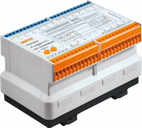
MODEX Regel- und Steuerkomponente
PROFIBUS-Interface 16 x digital out Ex i
Betriebsanleitung (Original) Typ 07-7331-2301/1000 bzw. 1100
PROFIBUS-Interface 16 NAMUR in (16 x digital in Ex i)
Typ 07-7331-2303/0000 (Standard) bzw. 1000 (Invertiert)
PROFIBUS-Interface 16 x digital out Ex i PROFIBUS-Interface 16 NAMUR in (16 x digital in Ex i)
Typ 07-7331-2301/1000 bzw. 1100 Typ 07-7331-2303/0000 (Standard) bzw. 1000 (Invertiert)
Elektrische Daten Elektrische Daten
Versorgungsspannung Versorgungsspannung
DC 24 V (20 bis 30) V DC 24 V (20 bis 30) V
Elektronik (L+, L-) Elektronik (L+, L-)
Leistungsaufnahme (L+, L-) 2,5 W Leistungsaufnahme (L+, L-) 5,1 W
Versorgungsspannung DC 24 V (20 bis 30) V Verpolungsschutz (L+, L-) Ja
Ausgänge (U2+, U2-)
Verlustleistung max. 5,1 W (Modul), bei 16
für Not-Aus geeignet geschlossenen Eingängen
Ausgangsleistung (U+, U-) 15 W (max.) Galvanische Trennung Versorgung//Bus//Schaltung//
Verpolungsschutz (L+, L-, Ja Ausgänge//Eingänge
U+, U-) Display Status ON, BF, SF
Verlustleistung max. 8 W (Modul) Eingänge 16 x Doppel LED
Galvanische Trennung Versorgung//Bus//Schaltung// - LED gelb,
Ausgänge bedämpft
Busschnittstelle RS485 mit Schraubklemmen - LED rot,
Bruch/
Anzeigen Status ON, BF, SF, U2 Schluss
Ausgänge - LED gelb, aktiv Eingänge
- LED rot,
Sensorversorgung Ua = 8,2 V
Schluss
Schaltschwellen Bruch < 0,23 mA
Ausgänge Bedämpft < 1,2 mA
Ausgangsspannung DC 18,1 V (bei U+ ≥ 22 V) Unbedämpft > 2,1 mA
Schluss > 7,4 mA
Ausgangsdaten IN = 30 mA Ri = 220 Ω
Übertragbare Frequenz 100 Hz
IN = 35 mA Ri = 180 Ω
Leitungsüberwachung Sammelstörung über Bus und
Kurzschlussfestigkeit Bedingt kurzschlussfest Relaiskontakt AC 230 V/3 A/100
Verpolungsschutz Ja VA
Leitungsüberwachung Sammelstörung über Bus
Die Ausgänge können separat mit Spannung versorgt werden.
Diese Spannung kann z. B. über Not-Aus abgeschaltet werden.
Betriebsbewährung kann bei BARTEC eingeholt werden.
01-7331-7D0012 / Version:A 15.02 2022 / 405499
Max-Eyth-Straße 16 Tel.: +49 7931 597-0 info@bartec.de Vorbehalt Technische Änderungen behalten wir uns vor.
DE GmbH 97980 Bad Mergentheim Fax: +49 7931 597-119 www.bartec.de Änderungen, Irrtümer und Druckfehler begründen 5/28
Deutschland keinen Anspruch auf Schadensersatz.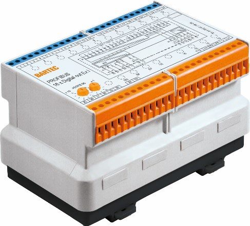
MODEX Regel- und Steuerkomponente
PROFIBUS-Interface 16 x digital out Ex i
Betriebsanleitung (Original) Typ 07-7331-2301/1000 bzw. 1100
PROFIBUS-Interface 16 NAMUR in (16 x digital in Ex i)
Typ 07-7331-2303/0000 (Standard) bzw. 1000 (Invertiert)
Das Modul ist SYNC fähig und kann auf Kommando vom GEFAHR
Master den momentanen Zustand der Ausgänge einfrieren
Unsachgemäßer Einsatz, fehlerhafte Montage und Bedienung
bis vom Master das nächste SYNC Kommando kommt.
gefährden den Explosionsschutz und können zu schweren
Personen- oder Sachschäden führen.
Das Modul ist FREEZE fähig und kann auf Kommando vom Die nachfolgenden besonderen Bedingungen beachten!
Master den momentanen Zustand der Eingänge einfrieren (1) Das Gehäuse ist werkseitig verschlossen und darf nicht
bis vom Master das nächste FREEZE Kommando kommt. geöffnet werden.
(2) Vor der Montage prüfen, ob sich die Komponente in einem
Produktkennzeichnung sauberen und unbeschädigten Zustand befindet.
(3) Die maximale Umgebungstemperatur und Luftfeuchte
siehe Seite 10 und Seite 11 (nicht kondensierend) einhalten.
(4) Spannungsfreiheit sicherstellen (Verbraucher mit
5. Transport und Lagerung Energiespeicher beachten)
(5) Benachbarte, unter Spannung stehende Teile abdecken.
(6) Das Modul auf die Hutschiene drücken bis es hörbar
ACHTUNG
einrastet.
Beschädigungen durch unsachgemäße Lagerung! (7) Sämtliche Anschlussschrauben und Anschlussklemmen
sind mit einem Drehmomentschlüssel, unter
Die Lager- und Transporttemperaturen beachten. Berücksichtigung des empfohlenen Anschlussdreh-
Für den Transport und Lagerung die Originalverpackung momentes von 0,4 Nm bis 0,7 Nm, für Anschluss-
verwenden. schrauben und Anschlussklemmen anzuziehen. Dies ist
durch geeignete Maßnahmen sicherzustellen.
6. Montage
7. Inbetriebnahme
Rechts neben dem Modul sind eine oder zwei Erdungs- Vor der Inbetriebnahme prüfen:
klemmen zu setzen. (1) Modul vorschriftsmäßig installiert?
Die zwei PA-Klemmen des Moduls sind mit je einer (2) Gehäuse nicht beschädigt?
2,5 mm2 Leitung mit der Erdungsklemme zu verbinden. (3) Anschluss ordnungsgemäß ausgeführt?
(4) Korrekte Verdrahtung überprüft?
Anschlussplan/Klemmenbelegung Nach der durchgeführten Kontrolle kann das Gerät in Betrieb
siehe Seite 10 und Seite 11 genommen werden.
WARNUNG
Beschädigungen durch unsachgemäße Handhabung!
Montageort außerhalb des Ex-Bereiches im Gehäuse
mindestens IP20 oder geschlossene Schaltanlagen.
Die Montage, Demontage, Installation und Inbetriebnahme darf
01-7331-7D0012 / Version:A 15.02 2022 / 405499
ausschließlich Fachpersonal ausführen, das für die Montage
von elektrischen Komponenten im explosionsgefährdeten
Bereich befugt und ausgebildet ist.
Beim Errichten oder beim Betrieb explosionsgeschützter
elektrischer Anlagen sind die einschlägigen Errichtungs- und
Betriebsbestimmungen zu beachten, wie z.B. RL 2014/34/EU,
BetrSichV, EN/IEC 60079-14, die Reihe DIN VDE 0100 oder
andere national geltende Standards oder Verordnungen.
Max-Eyth-Straße 16 Tel.: +49 7931 597-0 info@bartec.de Vorbehalt Technische Änderungen behalten wir uns vor.
DE GmbH 97980 Bad Mergentheim Fax: +49 7931 597-119 www.bartec.de Änderungen, Irrtümer und Druckfehler begründen 6/28
Deutschland keinen Anspruch auf Schadensersatz.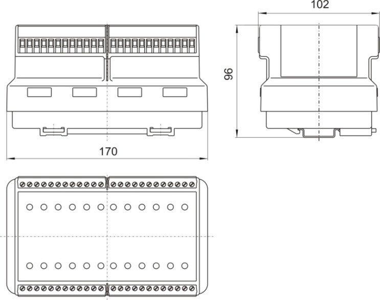
MODEX Regel- und Steuerkomponente
PROFIBUS-Interface 16 x digital out Ex i
Betriebsanleitung (Original) Typ 07-7331-2301/1000 bzw. 1100
PROFIBUS-Interface 16 NAMUR in (16 x digital in Ex i)
Typ 07-7331-2303/0000 (Standard) bzw. 1000 (Invertiert)
9. Projektierung
8. Betrieb
PROFIBUS-Interface 16 x digital out Ex i
GEFAHR Typ 07-7331-2301/1000 bzw. 1100
Es besteht Lebensgefahr bei nicht bestimmungsgemäßer Bitzuordnung - Ausgangskanäle
Verwendung! Bit 7 6 5 4 3 2 1 0
Besondere Bedingungen zum Explosionsschutz einhalten. Byte 0 16 15 14 13 12 11 10 9
Nur im zugelassenen Temperaturbereich betreiben. Byte 1 8 7 6 5 4 3 2 1
Bei Busausfall (Kommunikationsfehler) gehen die Ausgänge in
den Fail-Safe-Mode (gehen auf 0, und werden abgeschaltet!) Diagnose
Im Störfall muss das Gerät außer Betrieb gesetzt werden. Das Modul liefert auf Anforderung (SlaveDiag-Request)
Diagnosedaten (SlaveDiag-Response) an den Master,
Adressierung die neben der Standard-Diagnose auch eine modul-
spezifische Diagnose enthalten:
Byte Profibus Standard-Diagnose
0-5 (Kommunikationsstatus, Masteradresse, Profibus-ID)
Header-Byte (Anzahl der nachfolgenden Diagnose-
Byte 6 Bytes einschl. Header – hier: 7)
Byte 7 7 6 5 4 3 2 1 0
Die PROFIBUS-DP Adresse kann mittels der Drehschalter Diag. - - - U2 - - - -
x1 und x10 im Bereich von 01 bis 99 eingestellt werden. Nicht verwendet (immer 0)
Byte 8
Bit 8 - 15
Eine Adressänderung wird bei Spannungswiederkehr
übernommen. Byte 9 23 22 21 20 19 18 17 16
Kanal 8 7 6 5 4 3 2 1
Byte 10 31 30 29 28 27 26 25 24
LED Anzeigen Kanal 16 15 14 13 12 11 10 9
Byte Nicht verwendet (immer 0)
Farbe/
11 - 12 Bit 32 - 47
LED Zustan Meldungen
d
Die Zuordnung der Bits (Unit-Diag-Bits) in Byte 7, 9, 10
ON grün Spannung (L+/L-) vorhanden
zu den Kanalnummern ist in der GSD festgelegt.
aus PROFIBUS-DP Kommunikation aktiv
BF
rot Busfehler am PROFIBUS-DP Beispiel: Bei Fehler (Kurzschluss) am
Statusfehler - Kurzschluss oder U2 fehlt Kanal 6 wird das Bit 21 auf 1 gesetzt.
SF rot
Sammelmeldung für alle Ein-/Ausgänge
U2 grün Spannung U2 vorhanden (nur 2301) Hinweis: Bit 4 im Byte 7 wird auf 1 gesetzt, wenn
Spannung U2 (Klemmen U+/U-) fehlt
01-7331-7D0012 / Version:A 15.02 2022 / 405499
gelb Eingänge bzw. Ausgänge aktiv
1-16
rot Bruch (nur 2303) oder Schluss
Zugehörige GSD-Datei
Download: http://automation.bartec.de/
Dateiname: BARX2301.gsd
Max-Eyth-Straße 16 Tel.: +49 7931 597-0 info@bartec.de Vorbehalt Technische Änderungen behalten wir uns vor.
DE GmbH 97980 Bad Mergentheim Fax: +49 7931 597-119 www.bartec.de Änderungen, Irrtümer und Druckfehler begründen 7/28
Deutschland keinen Anspruch auf Schadensersatz.MODEX Regel- und Steuerkomponente
PROFIBUS-Interface 16 x digital out Ex i
Betriebsanleitung (Original) Typ 07-7331-2301/1000 bzw. 1100
PROFIBUS-Interface 16 NAMUR in (16 x digital in Ex i)
Typ 07-7331-2303/0000 (Standard) bzw. 1000 (Invertiert)
Diagnose
PROFIBUS-Interface 16 NAMUR in (16 x digital in Ex i)
Typ 07-7331-2303/0000 (Standard) or 1000 (Invertiert) Das Modul liefert auf Anforderung (SlaveDiag-Request)
Diagnosedaten (SlaveDiag-Response) an den Master,
Parameterisation
die neben der Standard-Diagnose auch eine modul-
Bit 7 6 5 4 3 2 1 0
spezifische Diagnose enthalten:
Mask bit for input
8 7 6 5 4 3 2 1
channel byte 1
Profibus Standard-Diagnose
Mask bit for Byte
(Kommunikationsstatus, Masteradresse, Profibus-
16 15 14 13 12 11 10 9 0-5
Input channel byte ID)
2 Header-Byte (Anzahl der nachfolgenden
Byte 6 Diagnose-Bytes einschl. Header – hier: 7)
Die Diagnose kann für jeden Kanal abgeschaltet werden
(Maskenbit = 1). Byte Nicht verwendet (immer 0)
7-8 Bit 0 - 15
Gerätespezifische Parameter der GSD (Bruch/Schluß Erkennung): Byte 9 23 22 21 20 19 18 17 16
Kanal 8 7 6 5 4 3 2 1
Byte 10 31 30 29 28 27 26 25 24
Kanal 16 15 14 13 12 11 10 9
Byte Nicht verwendet (immer 0)
11 - 12 Bit 32 - 47
Die Zuordnung der Bits (Unit-Diag-Bits) in Byte 9 und 10
zu den Kanalnummern ist in der GSD festgelegt.
Beispiel: Bei Fehler (Bruch oder Kurzschluss) am
Kanal 6 wird das Bit 21 auf 1 gesetzt.
Zustandstabelle Typ: 07-7331-2303/0000 (Standard) Zugehörige GSD-Datei
Download: http://automation.bartec.de/
Dateiname: BARX2903.gsd
Zustandstabelle Typ: 07-7331-2303/1000 (Invertiert)
01-7331-7D0012 / Version:A 15.02 2022 / 405499
Max-Eyth-Straße 16 Tel.: +49 7931 597-0 info@bartec.de Vorbehalt Technische Änderungen behalten wir uns vor.
DE GmbH 97980 Bad Mergentheim Fax: +49 7931 597-119 www.bartec.de Änderungen, Irrtümer und Druckfehler begründen 8/28
Deutschland keinen Anspruch auf Schadensersatz.MODEX Regel- und Steuerkomponente
PROFIBUS-Interface 16 x digital out Ex i
Betriebsanleitung (Original) Typ 07-7331-2301/1000 bzw. 1100
PROFIBUS-Interface 16 NAMUR in (16 x digital in Ex i)
Typ 07-7331-2303/0000 (Standard) bzw. 1000 (Invertiert)
Unsere Geräte sind elektrische Geräte die ausschließlich für
10. Fehlersuche und Störbeseitigung den gewerblichen Gebrauch vorgesehen sind (sog. B2B-
Geräte gemäß WEEE-Richtlinie). Die WEEE-Richtlinie gibt
Sollten beim Verbindungsaufbau Probleme auftreten, so den Rahmen für eine EU-weit gültige Behandlung von
überprüfen Sie bitte folgende Punkte: Elektro-Altgeräten vor. Die Komponenten müssen daher
1. LED Meldungen beachtet? nach den jeweiligen länderspezifischen Vorschriften
2. Verdrahtung und Anschlüsse kontrollieren entsorgt werden.
3. Korrekte Verbindung zwischen Steuerung und Endgerät? Alle bei uns erworbenen Produkte können im Falle einer
4. Sind alle Schraubklemmen korrekt angezogen? Entsorgung von unseren Kunden an uns zurückgesendet
werden. Die Kosten für Versand/Verpackung trägt der
5. Ist die richtige Baudrate eingestellt?
Absender.
6. Ist die Übertragungsstrecke für die gewählte Baudrate nicht
zu groß?
7. Sind alle Adressen richtig eingestellt? 13. Änderungen im Dokument
8. Wurde das System nach der letzten Änderung der
Busadressen neu gestartet? Die Geräte werden durch Im Zweifelsfall gilt die deutsche Ausgabe, da es nicht möglich ist
Wiedereinschalten neu initialisiert. Fehler bei Drucklegung und Übersetzung auszuschließen. Bei
9. Ist der Bus richtig terminiert (letztes Modul) und die Brücke, Rechtsstreitigkeiten gelten außerdem die „Allgemeinen
richtig gesetzt? Geschäftsbedingungen“ der BARTEC Gruppe.
10. Richtlinien für die einzelnen Baugruppen der Software
Die aktuellste Version der Datenblätter, Betriebsanleitungen,
beachten.
Zertifikate und EG-Konformitätserklärungen kann auf
www.bartec.de heruntergeladen oder direkt bei der BARTEC
11. Wartung, Inspektion, Reparatur GmbH angefordert werden.
Alle Arbeiten sind ausschließlich durch befugtes Fachpersonal 14. Bestellnummern
auszuführen.
Wartung
PROFIBUS Interface 16 x digital out Ex i
Bei sachgerechtem Betrieb, unter Beachtung der Montagehinweise
und Umgebungsbedingungen, ist keine Wartung erforderlich. Bestellnummer
07-7331-2301/0000 bzw. 1100
Inspektion
Nach EN/IEC 60079-17 und EN/IEC 60079-19 ist der Betreiber von PROFIBUS Interface 16 NAMUR in (16 x
elektrischen Anlagen in explosionsgefährdeten Bereichen ver- digital in Ex i)
pflichtet, diese Anlagen von einer Elektrofachkraft überprüfen zu
lassen, um sicherzustellen, dass sie sich in einem Bestellnummer
ordnungsgemäßen Zustand befinden. 07-7331-2303/0000 (Standard) bzw. 1000 (Invertiert)
Reparatur
Es darf keine Reparatur durchgeführt werden. Bei Fragen wenden
01-7331-7D0012 / Version:A 15.02 2022 / 405499
Sie sich bitte an die BARTEC GmbH. 15. Serviceadresse
12. Entsorgung BARTEC GmbH
Max-Eyth-Straße 16
97980 Bad Mergentheim
Die Regel- und Steuerkomponente enthält Metall-, Kunststoff-Teile Deutschland
und elektronische Bauteile. Telefon +49 7931 597-0
WEEE-Reg.-Nr. der BARTEC GmbH: Fax +49 7931 597-119
DE 95940350 E-Mail: info@bartec.de
Internet: www.bartec.de
Max-Eyth-Straße 16 Tel.: +49 7931 597-0 info@bartec.de Vorbehalt Technische Änderungen behalten wir uns vor.
DE GmbH 97980 Bad Mergentheim Fax: +49 7931 597-119 www.bartec.de Änderungen, Irrtümer und Druckfehler begründen 9/28
Deutschland keinen Anspruch auf Schadensersatz.MODEX Regel- und Steuerkomponente
PROFIBUS-Interface 16 x digital out Ex i
Betriebsanleitung (Original) Typ 07-7331-2301/1000 bzw. 1100
PROFIBUS-Interface 16 NAMUR in (16 x digital in Ex i)
Typ 07-7331-2303/0000 (Standard) bzw. 1000 (Invertiert)
Produktkennzeichnung PROFIBUS-Interface 16 x digital out Ex i Typ 07-7331-2301/1000 bzw. 1100
Typenschild
Typ 07-7331-2301/1000 Seitenschild 1 Seitenschild 2
Typ 07-7331-2301/1100 Seitenschild 1 Seitenschild 2
01-7331-7D0012 / Version:A 15.02 2022 / 405499
Max-Eyth-Straße 16 Tel.: +49 7931 597-0 info@bartec.de Vorbehalt Technische Änderungen behalten wir uns vor.
DE GmbH 97980 Bad Mergentheim Fax: +49 7931 597-119 www.bartec.de Änderungen, Irrtümer und Druckfehler begründen 10/28
Deutschland keinen Anspruch auf Schadensersatz.MODEX Regel- und Steuerkomponente
PROFIBUS-Interface 16 x digital out Ex i
Betriebsanleitung (Original) Typ 07-7331-2301/1000 bzw. 1100
PROFIBUS-Interface 16 NAMUR in (16 x digital in Ex i)
Typ 07-7331-2303/0000 (Standard) bzw. 1000 (Invertiert)
Anschlussplan/Klemmenbelegung PROFIBUS-Interface 16 x digital out Ex i
Typ 07-7331-2301/1000 bzw. 1100
01-7331-7D0012 / Version:A 15.02 2022 / 405499
Max-Eyth-Straße 16 Tel.: +49 7931 597-0 info@bartec.de Vorbehalt Technische Änderungen behalten wir uns vor.
DE GmbH 97980 Bad Mergentheim Fax: +49 7931 597-119 www.bartec.de Änderungen, Irrtümer und Druckfehler begründen 11/28
Deutschland keinen Anspruch auf Schadensersatz.MODEX Regel- und Steuerkomponente
PROFIBUS-Interface 16 x digital out Ex i
Betriebsanleitung (Original) Typ 07-7331-2301/1000 bzw. 1100
PROFIBUS-Interface 16 NAMUR in (16 x digital in Ex i)
Typ 07-7331-2303/0000 (Standard) bzw. 1000 (Invertiert)
Produktkennzeichnung PROFIBUS-Interface 16 NAMUR in (16 x digital in Ex i)
Typ 07-7331-2303/0000 (Standard) bzw. 1000 (Invertiert)
Typenschild
Typ 07-7331-2303/0000 Seitenschild 1 Seitenschild 2
Typ 07-7331-2303/1000 Seitenschild 1 Seitenschild 2
01-7331-7D0012 / Version:A 15.02 2022 / 405499
Max-Eyth-Straße 16 Tel.: +49 7931 597-0 info@bartec.de Vorbehalt Technische Änderungen behalten wir uns vor.
DE GmbH 97980 Bad Mergentheim Fax: +49 7931 597-119 www.bartec.de Änderungen, Irrtümer und Druckfehler begründen 12/28
Deutschland keinen Anspruch auf Schadensersatz.MODEX Regel- und Steuerkomponente
PROFIBUS-Interface 16 x digital out Ex i
Betriebsanleitung (Original) Typ 07-7331-2301/1000 bzw. 1100
PROFIBUS-Interface 16 NAMUR in (16 x digital in Ex i)
Typ 07-7331-2303/0000 (Standard) bzw. 1000 (Invertiert)
Anschlussplan/Klemmenbelegung PROFIBUS-Interface 16 NAMUR in (16 x digital in Ex i)
Typ 07-7331-2303/0000 (Standard) bzw. 1000 (Invertiert)
01-7331-7D0012 / Version:A 15.02 2022 / 405499
Max-Eyth-Straße 16 Tel.: +49 7931 597-0 info@bartec.de Vorbehalt Technische Änderungen behalten wir uns vor.
DE GmbH 97980 Bad Mergentheim Fax: +49 7931 597-119 www.bartec.de Änderungen, Irrtümer und Druckfehler begründen 13/28
Deutschland keinen Anspruch auf Schadensersatz.MODEX Regel- und Steuerkomponente
PROFIBUS-Interface 16 x digital out Ex i
Betriebsanleitung (Original) Typ 07-7331-2301/1000 bzw. 1100
PROFIBUS-Interface 16 NAMUR in (16 x digital in Ex i)
Typ 07-7331-2303/0000 (Standard) bzw. 1000 (Invertiert)
EU Konformität
01-7331-7D0012 / Version:A 15.02 2022 / 405499
Alle Prüfbescheinigungen siehe www.bartec.de
Max-Eyth-Straße 16 Tel.: +49 7931 597-0 info@bartec.de Vorbehalt Technische Änderungen behalten wir uns vor.
DE GmbH 97980 Bad Mergentheim Fax: +49 7931 597-119 www.bartec.de Änderungen, Irrtümer und Druckfehler begründen 14/28
Deutschland keinen Anspruch auf Schadensersatz.MODEX Regulating and control components
PROFIBUS-Interface 16 x digital out Ex i
Operation Instruction (Translation) Type 07-7331-2305/1000 or 1100
PROFIBUS-Interface 16 NAMUR in (16 x digital in Ex i)
Type 07-7331-2303/0000 (Standard) or 1000 (Inverted)
1. Definition
PROFIBUS Interface 16 x digital out Ex i PROFIBUS Interface 16 NAMUR in (16 x Ex i digital in)
Type 07-7331-2301/1000 or 1100 Type 07-7331-2303/0000 (Standard) or 1000 (Inverted)
In the Ex i version, the MODEX digital out Ex i module can control In the Ex i version, the MODEX Ex i digital in module with 16 digital
various actuators using 16 digital outputs. During operation, a inputs enables 16 binary signals to be evaluated. For example,
channel can be short- circuited on the short-circuit proof outputs NAMUR sensors, optocouplers, mechanical contacts or other
(short-circuit proof to a limited extent). For example, intrinsically actuating elements can be im- ported as signals in an intrinsically
safe solenoid valves and intrinsically safe signal transmitters can safe manner. The module is connected to the process control
be controlled as actuators. The controlled actuators can be system via the PROFIBUS-DP. This is also displayed on the module
switched off by an emergency stop via a second power supply con- itself using LEDs. Diagnostics data indicating the status of the
nection on the module on terminals U- and U+. The module is outputs with respect to a disconnection or short-circuit can also be
connected to the process control system via the PROFIBUS-DP. transmitted in addition to the user data. This is also displayed on the
Coding rotary switches are available for addressing the module. module itself using LEDs.
Diagnostics data indicating the status of the outputs with respect
to a disconnection or short-circuit can also be transmitted in
addition to the user data. This is also displayed on the module itself
using LEDs.
Co-applicable documents
Industrial Requirements in Zone 1
- Declaration of EU conformity
The control and regulating components are approved as "Ex d
flameproof enclosures" with terminals in "Ex e increased safety". - Test certificates
01-7331-7D0012 / Version:A 15.02 2022 / 405499
Since the open connecting terminals are Ex e, the modules are See: www.bartec.de
given a partial certificate with the "U" marking. The retention of these documents is mandatory!
Special Note concerning the "U" marking:
The control and regulating components must be installed in an
enclosure that meets the requirements of a recognised type of
protection in accordance EN/IEC 60079-0, min. protection type
IP54. When installing in an enclosure with “increased safety "e"”,
the clearance and creep age distances in Tables 1+2 in
IEC/EN 60079-7 must be complied with.
Max-Eyth-Straße 16 Tel.: +49 7931 597-0 info@bartec.de Vorbehalt Technische Änderungen behalten wir uns vor.
DE GmbH 97980 Bad Mergentheim Fax: +49 7931 597-119 www.bartec.de Änderungen, Irrtümer und Druckfehler begründen 1/28
Deutschland keinen Anspruch auf Schadensersatz.MODEX Regulating and control components
PROFIBUS-Interface 16 x digital out Ex i
Operation Instruction (Translation) Type 07-7331-2305/1000 or 1100
PROFIBUS-Interface 16 NAMUR in (16 x digital in Ex i)
Type 07-7331-2303/0000 (Standard) or 1000 (Inverted)
CSA
2. Explosion protection and approvals
Test certificate 2011-2484303U
Regulating and control components
Type 07-7331-2301/1000 or 1100 INMETRO
ATEX Test certificate UL-BR 13.0397U
Test certificate PTB 97 ATEX 1066 U
TÜV 00 ATEX 1649
Customs Union Russia (EAC)
Ex protection type II 2(1)G Ex db e [ib] IIC/IIB Gb Test certificate RU C-DE.BH02.B.00005
I M2 Ex db e [ib] I Mb
Further certificates www.bartec.de
Standards EN 60079-0:2012+A11:2013
In accordance with EN 60079-1:2014 EU Conformity
Directive 2014/34/EU EN 60079-7:2007
EN 60079-11:2012 ATEX Directive 2014/34/EU
IECEx RoHS Directive 2011/65/EU
Test certificate PTB 11.0082U EMC Directive 2014/30/EU 2014/30/EU
TUN 11.0035X Enclosure protection class EN 60529:1991+A1:2000+A2:2013
Ex protection type Ex db e [ib] IIC/IIB Gb Product labelling 0044
Ex db e [ib] I Mb Safety data
Type 07-7331-2301/1000
Regel- und Steuerkomponente U0 = 21 V
Typ 07-7331-2303/0000 or 1000 I0 = 111,6 mA
P0 = 586 mW
ATEX
Characteristic: linear
Test certificate PTB 97 ATEX 1066 U
Ex ib IIC L0 2,1 1 0,5 0,2 0,1 0,05
TÜV 98 ATEX 1355 X mH mH mH mH mH mH
Ex protection type II 2(1)G Ex db e [ia Ga] IIC Gb C0 93 96 110 150 180 188
I M2 Ex db e [ia Ma] I Mb nF nF nF nF nF nF
IECEx Ex ib IIB/IIIB/IIC L0 12 10 5 0,5 0,2 0,1
Test certificate PTB 11.0082U mH mH mH mH mH mH
TUN 11.0024X C0 540 620 710 750 910 1,1
nF nF nF nF nF nF
Ex protection type Ex db e [ia Ga] IIC Gb
Ex db e [ia Ma] I Mb
01-7331-7D0012 / Version:A 15.02 2022 / 405499
Special conditions
(1) The regulating and control components must be installed in an
enclosure which corresponds to the requirements of a
recognised class of protection in accordance with
EN 60 079-0, Section 1.2.
(2) When installing in an enclosure with an increased
safety class of protection “e” in accordance with
EN 60079-7:2007, the clearance and creep age distances set
out under Section 4.3, Section 4.4 and Table 1 must be
complied with.
(3) The component can be used in Group I and II because the
requirements of the standard are identical in this case.
Max-Eyth-Straße 16 Tel.: +49 7931 597-0 info@bartec.de Vorbehalt Technische Änderungen behalten wir uns vor.
DE GmbH 97980 Bad Mergentheim Fax: +49 7931 597-119 www.bartec.de Änderungen, Irrtümer und Druckfehler begründen 2/28
Deutschland keinen Anspruch auf Schadensersatz.MODEX Regulating and control components
PROFIBUS-Interface 16 x digital out Ex i
Operation Instruction (Translation) Type 07-7331-2305/1000 or 1100
PROFIBUS-Interface 16 NAMUR in (16 x digital in Ex i)
Type 07-7331-2303/0000 (Standard) or 1000 (Inverted)
Safety data 3. Safety Instructions
Type 07-7331-2301/1100
Designated use
U0 = 21 V The control and regulating components may only be operated in a
I0 = 139,2 mA clean, undamaged condition and is admitted only for a proper and
P0 = 731 mW designated use. With infringement any guarantee and
Characteristic: linear manufacturer`s responsibility goes out.
The correct laws, norms and directives for use or project engineering
Ex ib IIC L0 2,1 1 mH 0,5 0,2 0,1 0,05 must be kept.
mH mH mH mH mH
The assembly/dismantling of the regulating and control components
C0 93 96 nF 110 150 180 188 must be conducted by qualified personnel authorised and trained to
nF nF nF nF nF install electrical components in potentially explosive areas. The user
manual should be read and have been understood. The
Ex ib IIB/IIIB/IIC L0 12 10 5 0,5 0,2 0,1 responsibility for the assembly/dismantling, installation, service and
mH mH mH mH mH mH the operation lies carries the operator.
C0 540 620 710 750 910 1,1
nF nF nF nF nF nF
Danger, Warning and Note Symbols
Safety instructions and warnings are specially highlighted in these
Safety data operating instructions and marked by symbols.
Type 07-7331-2303/0000 (Standard) bzw. 1000 (Inverted)
U0 = 12,3 V DANGER
I0 = 31,8 mA The DANGER sign draws attention to a direct threat which if not
P0 = 97,8 mW avoided will lead to death or very serious injuries.
Um = 253 V
Ex ib IIC L0 44 20 10 5 2 1 WARNING
mH mH mH mH mH mH WARNING draws attention to a possible threat which if not avoided
C0 200 320 400 480 610 730 can lead to death or very serious injuries.
nF nF nF nF nF nF
Ex ib IIB/IIIB/IIC L0 100 50 20 10 5 2 CAUTION
mH mH mH mH mH mH
CAUTION draws attention to a possible danger which if not avoided
C0 1,2 1,6 2 nF 2,3 2,7 3,4 can lead to slight or minor injuries.
nF nF nF nF nF
ATTENTION
Ex ib IIC L0 0,5 0,2 0,1 ATTENTION draws attention to a potentially damaging situation
mH mH mH which if not avoided can cause damage to the equipment or to
C0 860 1,1 1,1 objects in its vicinity
nF nF nF
01-7331-7D0012 / Version:A 15.02 2022 / 405499
Ex ib IIB/IIIB/IIC L0 1 0,5 0,5 Important instructions and information on effective,
mH mH mH economical & environmentally compatible handling.
C0 4 4,8 4,8
nF nF nF
Max-Eyth-Straße 16 Tel.: +49 7931 597-0 info@bartec.de Vorbehalt Technische Änderungen behalten wir uns vor.
DE GmbH 97980 Bad Mergentheim Fax: +49 7931 597-119 www.bartec.de Änderungen, Irrtümer und Druckfehler begründen 3/28
Deutschland keinen Anspruch auf Schadensersatz.MODEX Regulating and control components
PROFIBUS-Interface 16 x digital out Ex i
Operation Instruction (Translation) Type 07-7331-2305/1000 or 1100
PROFIBUS-Interface 16 NAMUR in (16 x digital in Ex i)
Type 07-7331-2303/0000 (Standard) or 1000 (Inverted)
4. Technical Data Ambient conditions
Physical characteristics Ambient temperature -40 °C to +60 °C at
Temperature class T4
Construction flameproof clip-on enclosure
for TH 35 rail Storage/transport
-40 °C to +60 °C
temperature
Enclosure material high-quality thermoplastics
Vibration 2 g/7 mm, 5-200 Hz
Protection class (EN 60068-2-6) in all 3 axes
(EN/IEC 60529)
Shock
Electronic module IP 66 15 g, 11ms in all 3 axes
(EN 60068-2-27)
Terminals IP 20
Terminals with cover IP 30 Relative air humidity 5 % to 95 %
non-condensing
Electric connections terminals 2.5 mm2,
fine-stranded
Attachment onto mounting
TH 35 x 15 (7.5)
rail (EN/IEC 60715)
Terminal marking inscription label
Terminal screws M 2.5 x 0.45 mm
Terminal screw torque 0.4 Nm
Mounting position Any
Weight 2.1 kg
Dimensions
170 mm x 96 mm x 102 mm
(width x height x depth)
01-7331-7D0012 / Version:A 15.02 2022 / 405499
Max-Eyth-Straße 16 Tel.: +49 7931 597-0 info@bartec.de Vorbehalt Technische Änderungen behalten wir uns vor.
DE GmbH 97980 Bad Mergentheim Fax: +49 7931 597-119 www.bartec.de Änderungen, Irrtümer und Druckfehler begründen 4/28
Deutschland keinen Anspruch auf Schadensersatz.MODEX Regulating and control components
PROFIBUS-Interface 16 x digital out Ex i
Operation Instruction (Translation) Type 07-7331-2305/1000 or 1100
PROFIBUS-Interface 16 NAMUR in (16 x digital in Ex i)
Type 07-7331-2303/0000 (Standard) or 1000 (Inverted)
PROFIBUS-Interface 16 x digital out Ex i PROFIBUS-Interface 16 NAMUR in (16 x digital in Ex i)
Typ 07-7331-2301/1000 or 1100 Typ 07-7331-2303/0000 (Standard) or 1000 (Inverted)
Electrical Data Electrical Data
Supply voltage electronics DC 24 V (20 to 30) V Supply voltage electronics DC 24 V (20 to 30) V
(L+, L-) (L+, L-)
Power consumption (L+, L-) 2.5 W Power consumption (L+, L-) 5.1 W
Supply voltage Outputs (U2+, DC 24 V (20 to 30V) Reverse polarity protection Yes
U2-) suitable for emergency (L+, L-)
stop
Power dissipation max. 5.1 W (Module), at 16
Power output (U+, U-) 15 W (max.) closed inputs
Reverse polarity protection Yes Galvanic isolation Power supply//bus//circuitry//
(L+, L-,U+,U-) inputs
Power dissipation max. 8 W (Module) Bus interface RS485 with screw clamp
Galvanic isolation Power supply//bus//circuitry// Display Status ON, BF; SF
outputs
Inputs 16 x dual LED
Bus interface RS485 with screw clamp - LED yellow,
Display Status ON, BF; SF, U2 damped
- LED red,
Outputs - LED yellow,
open circuit/
active
short circuit
- LED red,
short-circuit Inputs
Outputs Sensor power supply Ua = 8,2 V
Switching threshold open circuit < 0,23 mA
Output voltage DC 18,1 V (at U+ ≥ 22 V) damped < 1,2 mA
Output data IN = 30 mA Ri = 220 Ω undamped > 2,1 mA
IN = 35 mA Ri = 180 Ω short circuit > 7,4 mA
Short circuit protection Conditionally short-circuit-proof Transmittable frequency 100 Hz
Reserve polarity protection Yes Line monitoring Group error message via bus
and relay contact AC 230 V/3
Circuit monitoring Combined fault via bus A/100 VA
Power to the outputs can be supplied separately. This power can
be turned off by an emergency stop, for example.
01-7331-7D0012 / Version:A 15.02 2022 / 405499
Max-Eyth-Straße 16 Tel.: +49 7931 597-0 info@bartec.de Vorbehalt Technische Änderungen behalten wir uns vor.
DE GmbH 97980 Bad Mergentheim Fax: +49 7931 597-119 www.bartec.de Änderungen, Irrtümer und Druckfehler begründen 5/28
Deutschland keinen Anspruch auf Schadensersatz.MODEX Regulating and control components
PROFIBUS-Interface 16 x digital out Ex i
Operation Instruction (Translation) Type 07-7331-2305/1000 or 1100
PROFIBUS-Interface 16 NAMUR in (16 x digital in Ex i)
Type 07-7331-2303/0000 (Standard) or 1000 (Inverted)
The module has a SYNC function and can freeze on DANGER
command of the master the current state of the outputs Incorrect use, faulty installation and operation jeopardise the
until the next SYNC command from the master comes. explosion protection and can lead to serious injuries and
damage to property.
The following special conditions must be heeded!
The module is able FREEZE and can freeze on command
of the master the current state of the inputs until the next (1) The enclosure has been sealed in the factory and may
FREEZE command from the master comes. not be opened.
(2) Before installation, check whether the components are in
a clean and perfect condition.
Product Marking (3) Keep the maximum surroundings temperature and aerial
See page 10 and page 11 dampness.
(4) Ensure the unit is dead (be aware of consumers with
stored energy)
5. Transport and Storage
(5) Cover any live neighbouring components.
(6) Press the module on the hat rail until it engages.
ATTENTION
(7) All screws and terminals must be tightened using a
Damage due to incorrect storage! torque wrench, taking account of the recommended
connection torque for screws and terminals of 0. 4 Nm to
Observe storage and transport temperatures.
0.7 Nm. Suitable measures must be taken to ensure this.
Use the original packaging for transport/storage.
7. Commissioning
6. Assembly
Check before commissioning:
One or two earthing terminals must be placed on the right (1) Has the module been installed correctly?
next to the module. (2) Is the enclosure undamaged?
The two equipotential bonding terminals on the module must (3) Has the connection been carried out correctly?
each be connected to the earthing terminal using a (4) Have you checked that the wiring is correct?
2.5 mm2 cable.
Once the final check has been conducted, the device can be put into
operation.
Wiring Diagram/Terminal Assignment
See page 10 and page 11
WARNING
Damage caused by incorrect use!
Installation outside of the hazardous area in the enclosure, at
least IP20 or closed switchgear.
01-7331-7D0012 / Version:A 15.02 2022 / 405499
The assembly, dismantling, installation and commissioning
may only be executed by a skilled electrician who has been
authorised and trained to carry out the assembly of electrical
components in a potentially explosive area.
The pertinent regulations for setting up and operation must be
observed when setting up or operating explosion protected
electrical installations. These include Directive 2014/34/EU,
BetrSichV (the German Ordinance on Industrial Health and
Safety), ENIEC 60079-14, the DIN VDE 0100 series or other
nationally applicable standards or regulations.
Max-Eyth-Straße 16 Tel.: +49 7931 597-0 info@bartec.de Vorbehalt Technische Änderungen behalten wir uns vor.
DE GmbH 97980 Bad Mergentheim Fax: +49 7931 597-119 www.bartec.de Änderungen, Irrtümer und Druckfehler begründen 6/28
Deutschland keinen Anspruch auf Schadensersatz.MODEX Regulating and control components
PROFIBUS-Interface 16 x digital out Ex i
Operation Instruction (Translation) Type 07-7331-2305/1000 or 1100
PROFIBUS-Interface 16 NAMUR in (16 x digital in Ex i)
Type 07-7331-2303/0000 (Standard) or 1000 (Inverted)
Diagnostics
8. Operation
The module provides on request (SlaveDiag-Request)
DANGER diagnosis data (SlaveDiag-Response) to the master,
which contains also besides standard diagnosis, module specific
There is danger to life if the device is not used correctly! diagjnosis:
Comply with the special explosion protection conditions. Byte Profibus standard-diagnosis
Only operate within the approved temperature range. 0-5 (communication status, master address, Profibus-ID)
In case of bus failure (communication fault) the outputs switch Header-Byte (number of the following diagnosis
to failsafe mode (switch to 0, and get turned off). Byte 6 bytes incl. Header – here 7)
In failure the device must be closed down.
Byte 7 7 6 5 4 3 2 1 0
-
Diag. - - - U2 - - - -
Addressing Byte 8
Not used (always 0)
Bit 8 - 15
Byte 9 23 22 21 20 19 18 17 16
Channel 8 7 6 5 4 3 2 1
Byte 10 31 30 29 28 27 26 25 24
Channel 16 15 14 13 12 11 10 9
Byte Not used (always 0)
11 - 12 Bit 32 - 47
The PROFIBUS-DP address can be set in the range from The allocation of the bits (Unit-Diag-Bits) in byte 7, 9 and 10
01 to 99 using the rotary switches x1 and x10. to the channel number is fixed in the GSD.
An address change will be applied when the power is back
on. Example: With mistake (open circuit/short circuit) in channel 6 the bit
21 will be set to 1.
LED displays
Note: bit 4 in byte 7 will be set, if the supply voltage (terminal U2+,U2-
Colour/ ) is missing.
LED Messages
status
ON green Voltage (L+/L-) exists Corresponding GSD-file
off PROFIBUS-DP communication active
BF Download: http://automation.bartec.de/
red Bus error – error on PROFIBUS-DP
Filename: BARX2301.gsd
Status error - short circuit or U2 is missing
SF red Collective announcement for all entrances
and exits
U2 green Voltage U2 exists (only 2301)
01-7331-7D0012 / Version:A 15.02 2022 / 405499
yellow Inputs or outputs active and okay
1-16
red open circuit (only 2303) or short circuit
9. Project planning
PROFIBUS-Interface 16 x digital out Ex i
Typ 07-7331-2301/1000 or. 1100
Bit assignment – output channels
Bit 7 6 5 4 3 2 1 0
Byte 0 16 15 14 13 12 11 10 9
Byte 1 8 7 6 5 4 3 2 1
Max-Eyth-Straße 16 Tel.: +49 7931 597-0 info@bartec.de Vorbehalt Technische Änderungen behalten wir uns vor.
DE GmbH 97980 Bad Mergentheim Fax: +49 7931 597-119 www.bartec.de Änderungen, Irrtümer und Druckfehler begründen 7/28
Deutschland keinen Anspruch auf Schadensersatz.MODEX Regulating and control components
PROFIBUS-Interface 16 x digital out Ex i
Operation Instruction (Translation) Type 07-7331-2305/1000 or 1100
PROFIBUS-Interface 16 NAMUR in (16 x digital in Ex i)
Type 07-7331-2303/0000 (Standard) or 1000 (Inverted)
Diagnostics
PROFIBUS-Interface 16 NAMUR in (16 x digital in Ex i)
Typ 07-7331-2303/0000 (Standard) or 1000 (Inverted) The module provides on request (SlaveDiag-Request)
Diagnosis data (SlaveDiag-Response) to the master,
Parametrierung
which contains also besides standard diagnosis, module specific
Bit 7 6 5 4 3 2 1 0 diagnosis:
Bit for
Inputchannel 8 7 6 5 4 3 2 1
Byte 0 Profibus standard-diagnosis
Byte
(communication status, master address, Profibus-
Bit for 0-5
ID)
Inputchannel 16 15 14 13 12 11 10 9
Byte 1 Header-Byte (number of the following diagnosis
Byte 6
bytes incl. Header – here: 7)
The diagnosis can be switched off for every channel (mask bit 1) Byte Not used (always 0)
7–8 Bit 0 - 15
Device-Specific Parameters (Short/Break detection): Byte 9 23 22 21 20 19 18 17 16
Channel 8 7 6 5 4 3 2 1
Byte 10 31 30 29 28 27 26 25 24
Channel 16 15 14 13 12 11 10 9
Byte Not used (always 0)
11 - 12 Bit 32 - 47
The allocation of the bits (Unit-Diag-Bits) in byte 9 and 10 to the
channel number is fixed in the GSD.
Example: With mistake (break circuit/short circuit) in channel 6 the
bit 21 will be set to 1.
Status table Type: 07-7331-2303/0000 (Standard) Corresponding GSD-file
Download: http://automation.bartec.de/
Fillename: BARX2903.gsd
Status table Type: 07-7331-2303/1000 (Inverted)
01-7331-7D0012 / Version:A 15.02 2022 / 405499
Max-Eyth-Straße 16 Tel.: +49 7931 597-0 info@bartec.de Vorbehalt Technische Änderungen behalten wir uns vor.
DE GmbH 97980 Bad Mergentheim Fax: +49 7931 597-119 www.bartec.de Änderungen, Irrtümer und Druckfehler begründen 8/28
Deutschland keinen Anspruch auf Schadensersatz.MODEX Regulating and control components
PROFIBUS-Interface 16 x digital out Ex i
Operation Instruction (Translation) Type 07-7331-2305/1000 or 1100
PROFIBUS-Interface 16 NAMUR in (16 x digital in Ex i)
Type 07-7331-2303/0000 (Standard) or 1000 (Inverted)
Our devices involve electrical equipment which is only
10. Troubleshooting intended for commercial use (so-called B2B equipment in
accordance with the WEEE Directive).
Please check the following points if problems arise when setting
up a connection: The regulating and control components must be disposed
11. Have you paid attention to the LED messages? of in accordance with national regulations.
12. Check wiring and connections. Our customers may return any products procured from us
13. Is the connection between the controller and terminal device to our company for disposal. The sender must bear the
correct? costs for shipping/packing.
14. Have all screw terminals been correctly tightened?
15. Has the correct baud rate been set?
16. Is the transmission path too long for the selected baud rate?
13. Amendments to the Document
17. Have all addresses been set correctly?
In cases of doubt the German safety instructions apply because it
18. Has the system been restarted since last changing the bus
addresses? The devices are initialised after each restart. is not possible to rule out errors during printing and translation. The
19. Has the bus been correctly set (last module) and the jumper "General Terms and Conditions of Business" of the BARTEC
set correctly? Group moreover apply in the event of legal disputes.
20. Heed the guidelines for individual assemblies in the software. The current version of data sheets, operating instructions,
certificates and EC declarations of conformity can be downloaded
from www.bartec.de or directly requested from BARTEC GmbH.
11. Maintenance, Inspection, Repair
Only authorised and qualified personnel may do any work on the
14. Order Numbers
control and regulating component.
Maintenance PROFIBUS Interface 16 x digital out Ex i
If operated correctly in accordance with the installation instructions Order no.
and ambient conditions, it does not require maintenance. 07-7331-2301/0000 or 1100
Inspection
PROFIBUS Interface 16 NAMUR in (16 x
Under EN/IEC 60079-17 and EN/IEC 60079-19 the owner/ digital in Ex i)
managing operator of electric installations in hazardous areas is
obliged to have these installations checked by a qualified Order no.
electrician to ensure that they are in a proper condition. 07-7331-2303/0000 (Standard) or 1000 (Inverted)
Repair
The component must not be repaired. Please contact BARTEC 15. Service Address
GmbH if you have any questions.
BARTEC GmbH
01-7331-7D0012 / Version:A 15.02 2022 / 405499
12. Disposal Max-Eyth-Straße 16
97980 Bad Mergentheim
GERMANY
The regulating and control components contain metallic, plastic
and electronic parts. Phone +49 7931 597-0
Fax +49 7931 597-119
WEEE-Reg.-No. of the BARTEC GmbH:
DE 95940350 E-Mail: info@bartec.de
Internet: www.bartec.de
Max-Eyth-Straße 16 Tel.: +49 7931 597-0 info@bartec.de Vorbehalt Technische Änderungen behalten wir uns vor.
DE GmbH 97980 Bad Mergentheim Fax: +49 7931 597-119 www.bartec.de Änderungen, Irrtümer und Druckfehler begründen 9/28
Deutschland keinen Anspruch auf Schadensersatz.MODEX Regulating and control components
PROFIBUS-Interface 16 x digital out Ex i
Operation Instruction (Translation) Type 07-7331-2305/1000 or 1100
PROFIBUS-Interface 16 NAMUR in (16 x digital in Ex i)
Type 07-7331-2303/0000 (Standard) or 1000 (Inverted)
Product marking PROFIBUS Interface 16 x digital out Ex i Type 07-7331-2301/1000 or 1100
Type label
Type 07-7331-2301/1000 Side label 1 Side label 2
Type 07-7331-2301/1100 Side label 1 Side label 2
01-7331-7D0012 / Version:A 15.02 2022 / 405499
Max-Eyth-Straße 16 Tel.: +49 7931 597-0 info@bartec.de Vorbehalt Technische Änderungen behalten wir uns vor.
DE GmbH 97980 Bad Mergentheim Fax: +49 7931 597-119 www.bartec.de Änderungen, Irrtümer und Druckfehler begründen 10/28
Deutschland keinen Anspruch auf Schadensersatz.MODEX Regulating and control components
PROFIBUS-Interface 16 x digital out Ex i
Operation Instruction (Translation) Type 07-7331-2305/1000 or 1100
PROFIBUS-Interface 16 NAMUR in (16 x digital in Ex i)
Type 07-7331-2303/0000 (Standard) or 1000 (Inverted)
Wiring Diagram/Terminal Assignment PROFIBUS Interface 16 x digital out Ex i
Type 07-7331-2301/1000 or 1100
01-7331-7D0012 / Version:A 15.02 2022 / 405499
Max-Eyth-Straße 16 Tel.: +49 7931 597-0 info@bartec.de Vorbehalt Technische Änderungen behalten wir uns vor.
DE GmbH 97980 Bad Mergentheim Fax: +49 7931 597-119 www.bartec.de Änderungen, Irrtümer und Druckfehler begründen 11/28
Deutschland keinen Anspruch auf Schadensersatz.MODEX Regulating and control components
PROFIBUS-Interface 16 x digital out Ex i
Operation Instruction (Translation) Type 07-7331-2305/1000 or 1100
PROFIBUS-Interface 16 NAMUR in (16 x digital in Ex i)
Type 07-7331-2303/0000 (Standard) or 1000 (Inverted)
Product marking PROFIBUS Interface 16 NAMUR in (16 x digital in Ex i)
Type 07-7331-2303/0000 (Standard) or 1000 (Inverted)
Type label
Type 07-7331-2303/0000 Side label 1 Side label 2
Type 07-7331-2303/1000 Side label 1 Side label 2
01-7331-7D0012 / Version:A 15.02 2022 / 405499
Max-Eyth-Straße 16 Tel.: +49 7931 597-0 info@bartec.de Vorbehalt Technische Änderungen behalten wir uns vor.
DE GmbH 97980 Bad Mergentheim Fax: +49 7931 597-119 www.bartec.de Änderungen, Irrtümer und Druckfehler begründen 12/28
Deutschland keinen Anspruch auf Schadensersatz.MODEX Regulating and control components
PROFIBUS-Interface 16 x digital out Ex i
Operation Instruction (Translation) Type 07-7331-2305/1000 or 1100
PROFIBUS-Interface 16 NAMUR in (16 x digital in Ex i)
Type 07-7331-2303/0000 (Standard) or 1000 (Inverted)
Wiring Diagram/Terminal Assignment PROFIBUS Interface 16 NAMUR in (16 x digital in Ex i)
Type 07-7331-2303/0000 (Standard) or 1000 (Inverted)
01-7331-7D0012 / Version:A 15.02 2022 / 405499
Max-Eyth-Straße 16 Tel.: +49 7931 597-0 info@bartec.de Vorbehalt Technische Änderungen behalten wir uns vor.
DE GmbH 97980 Bad Mergentheim Fax: +49 7931 597-119 www.bartec.de Änderungen, Irrtümer und Druckfehler begründen 13/28
Deutschland keinen Anspruch auf Schadensersatz.MODEX Regulating and control components
PROFIBUS-Interface 16 x digital out Ex i
Operation Instruction (Translation) Type 07-7331-2305/1000 or 1100
PROFIBUS-Interface 16 NAMUR in (16 x digital in Ex i)
Type 07-7331-2303/0000 (Standard) or 1000 (Inverted)
EU Conformity
01-7331-7D0012 / Version:A 15.02 2022 / 405499
All certificates see www.bartec.de
Max-Eyth-Straße 16 Tel.: +49 7931 597-0 info@bartec.de Vorbehalt Technische Änderungen behalten wir uns vor.
DE GmbH 97980 Bad Mergentheim Fax: +49 7931 597-119 www.bartec.de Änderungen, Irrtümer und Druckfehler begründen 14/28
Deutschland keinen Anspruch auf Schadensersatz.BARTEC
BARTEC GmbH
Max-Eyth-Str. 16
97980 Bad Mergentheim
01-7331-7D0012 / Version:A 15.02 2022 / 405499
Deutschland
Tel.: +49 7931 597 0
info@bartec.com
bartec.comSie können auch lesen