Q-NETWORK 01ELT2067 MANUAL - EC-Power
←
→
Transkription von Seiteninhalten
Wenn Ihr Browser die Seite nicht korrekt rendert, bitte, lesen Sie den Inhalt der Seite unten
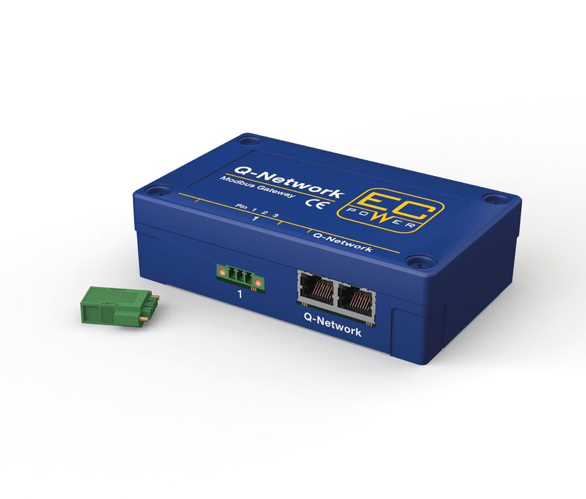
Q-NETWORK
M O D B U S G AT E WAY
0 1 E L T 2 0 6 7   M A N U A L

01DOC1030-03               03.2022
Gültig für / Valid for : Modbus Gateway - 01ELT2067 manual
Art. Nr.: 01DOC1030-03

EC POWER A/S
Samsøvej 25 • DK-8382 Hinnerup
T 0045 87 43 41 00 • E mail@ecpower.dk
VAT DK19228509

(DE) Technische Änderungen, Designabweichungen und Irrtümer vorbehalten.
Alle Bilder dienen ausschließlich der Veranschaulichung und können abweichen.

(EN) Subject to technical changes, design modifications and errors.
All pictures shown are for illustrative purposes only.

© by EC POWER A/S.
MODBUS GATEWAY

INHALTSVERZEICHNIS

1.   FUNKTION........................................................................................................................................................................................... 4

2.   KOMPONENTEN & WERKZEUG........................................................................................................................................................ 4
             KOMPONENTEN.....................................................................................................................................................................................................................................4
             WERKZEUG...............................................................................................................................................................................................................................................4

3.   EINBINDUNG....................................................................................................................................................................................... 5
     3.1     EINBINDUNG - EINE XRGI®-ANLAGE .........................................................................................................................................................................................5
             NETZWERKKABEL..................................................................................................................................................................................................................................5
             NETZABSCHLUSS..................................................................................................................................................................................................................................5
             SYSTEMSTECKER....................................................................................................................................................................................................................................5
     3.2     EINBINDUNG - MEHRERE XRGI®-ANLAGEN ..........................................................................................................................................................................6
             NETZWERKKABEL..................................................................................................................................................................................................................................6
             NETZABSCHLUSS..................................................................................................................................................................................................................................6
             SYSTEMSTECKER....................................................................................................................................................................................................................................6

4.   KONFIGURATION................................................................................................................................................................................ 7

5.   ANBINDUNG AN EXTERNE SYSTEME.............................................................................................................................................. 7

6.   FUNKTIONSDIAGNOSE..................................................................................................................................................................... 8
             BENÖTIGTE KOMPONENTEN..........................................................................................................................................................................................................8
             SERIELLER ADAPTER............................................................................................................................................................................................................................8
             KONTROLLNETZWERK.......................................................................................................................................................................................................................8
             MODBUS SOFTWARE..........................................................................................................................................................................................................................8

CONTENT

1.   FUNCTION........................................................................................................................................................................................... 9

2.   COMPONENTS & TOOLS.................................................................................................................................................................... 9
             COMPONENTS........................................................................................................................................................................................................................................9
             TOOLS..........................................................................................................................................................................................................................................................9

3.   INSTALLATION.................................................................................................................................................................................. 10
     3.1     INSTALLATION - ONE XRGI® SYSTEM .....................................................................................................................................................................................10
             NETWORK CABLE...............................................................................................................................................................................................................................10
             NETWORK TERMINATOR................................................................................................................................................................................................................10
             SYSTEM PLUG.......................................................................................................................................................................................................................................10
     3.2     INSTALLATION - MORE THAN ONE XRGI® SYSTEM .......................................................................................................................................................11
             NETWORK CABLE...............................................................................................................................................................................................................................11
             NETWORK TERMINATOR................................................................................................................................................................................................................11
             SYSTEM PLUG.......................................................................................................................................................................................................................................11

4.   CONFIGURATION.............................................................................................................................................................................. 12

5.   CONNECTION TO EXTERNAL SYSTEMS........................................................................................................................................ 12

6.   FUNCTIONALITY DIAGNOSE.......................................................................................................................................................... 13
             SERIAL ADAPTOR...............................................................................................................................................................................................................................13
             CONTROL NETWORK.......................................................................................................................................................................................................................13
             MODBUS SOFTWARE.......................................................................................................................................................................................................................13
                                                                                                                                                                                                                                                                                    01DOC1030-03 - STAND 03/2022

A.   APPENDIX.......................................................................................................................................................................................... 14
     Schnittstellenbeschreibung / Description of the interfaces

                                                                                                                                                                                                                                                                                3
DE        MODBUS GATEWAY

                              1.       FUNKTION
                                       Der Modbus Gateway ist eine Q-Network-Verbindungskomponente, die System-
                                       status-Informationen ermitteln kann. Er macht eine Vielzahl an Informationen
                                       zugänglich, die laufend vom XRGI®-System aktualisiert werden. Der Modbus
                                       Gateway erlaubt es außerdem, das XRGI®-System fernzuüberwachen; dies kann
                                       z.B. genutzt werden, wenn die VHP-Ready-Funktionalität gewünscht ist.

                                       Der Modbus Gateway hat zwei Hauptfunktionen:

                                       A U S L E S E N V O N I N F O R M AT I O N E N :
                                       Nach dem Anschluss an das Netzwerk stehen die Informationen sofort (ohne
                                       weitere Einrichtung) zur Verfügung.

                                       EXTERNE ANSTEUERUNG XRGI®-ANLAGE:
                                       Nach Initialisierung in der XRGI®-Steuerungssoftware kann der XRGI®-Betrieb
                                       durch eine externe Ansteuerung beeinflusst werden. Ist die externe Ansteuerung
                                       initialisiert, wird in der aktuellen Software-Version die XRGI®-Anlage ohne externe
                                       Ansteuerung im wärmegeführten Modus betrieben.

                                       Details zu den Hauptfunktionen sind in der Schnittstellenbeschreibung enthal-
                                       ten (siehe Appendix).

                                       V O R A U S S E T Z U N G E N Z U M E I N S AT Z
                                       ■  Der Modbus Gateway ist nur einsetzbar, wenn eine Displayplatine mit inte-
                                          griertem Modem im iQ-Schaltschrank vorhanden ist (bei der alten Display-
                                          platine ist das Modem separat). XRGI®-Anlagen mit älteren Displayplatinen
                                          können umgerüstet werden. EC POWER stellt hierzu ein Umrüst-Kit zur Ver-
                                          fügung.
                                       ■ Die Steuerung muss die Software-Version 1.11.5 oder höher haben. Ist in einer
                                          XRGI®-Anlage eine niedrigere Softwareversion gegeben, ist ein Software-Up-
                                          date erforderlich.

                              2.       KOMPONENTEN & WERK ZEUG

                                       KOMPONENTEN

                                       Artikel-Nr. 01ELT2067 - Lieferumfang

                                           POS ANZAHL BESCHREIBUNG
                                           1        1       Modbus Gateway-Box
                                           2        1       Systemsteckergehäuse
                                           3        1       Q-Netzwerkkabel 5m blau

                                       1                                      2                  3

                                       WERK ZEUG

                                       Kein Werkzeug notwendig
01DOC1030-03 - 03.2022

                         4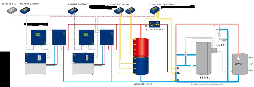
MODBUS GATEWAY   DE

3.    EINBINDUNG

      Bitte halten Sie die Reihenfolge der beschriebenen Arbeitsschritte ein.
      Dies erleichtert Ihre Arbeit und stellt die Qualität der Einbindung sicher.

3.1   E INBINDUNG - E INE XRG I®-ANL AG E

      Der Modbus Gateway darf maximal mit einer XRGI®-Anlage (Q-Net Kontroll-
      netzwerk) verbunden werden - Abweichungen verursachen Betriebsstörungen!

      Der Modbus Gateway muss auf einen vibrationsfreien Untergrund
      montiert werden.

      NETZWERKK ABEL

      ■   Verbinden Sie den Modbus Gateway (1) mit dem iQ-Schaltschrank über das
          CAT6 RJ45 Netzwerkkabel (3).
      ■   Stecken Sie das Netzwerkkabel am Modbus Gateway in die RJ45 Steckdose
          und im iQ-Schaltschrank in den Netzwerkeingang X100.

      NE T Z ABSCHLUSS

      ■   Decken Sie ungenutzte RJ45 Steckdosen mit einem Netzabschluss RJ45 (8x8)
          ISDN ab.

      SYSTEMSTECKER

      ■   Verbinden Sie den Modbus Gateway mit dem externen System über den
          Systemstecker (2).
                                                                                                           01DOC1030-03 - STAND 03/2022

                                                                                                       5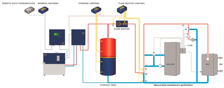
DE     MODBUS GATEWAY

                              3.2       E INBINDUNG - M EHR ER E XRG I®-ANL AG EN

                                        Der Modbus Gateway darf maximal mit einer XRGI®-Anlage (Q-Net Kontrollnetz-
                                        werk) verbunden werden. Der Modbus Gateway darf nicht zur Überbrückung
                                        von Kontrollnetzwerken zwischen zwei XRGI®-Anlagen verwendet werden. In
                                        einem Modbus-Netzwerk können mehrere Geräte vorhanden sein. Bei Mehr-
                                        modulanlagen ist pro XRGI®-Anlage ein Modbus Gateway zu installieren - Ab-
                                        weichungen verursachen Betriebsstörungen!

                                        Der Modbus Gateway muss auf einen vibrationsfreien Untergrund
                                        montiert werden.

                                        NETZWERKK ABEL

                                    ■    Verbinden Sie den Modbus Gateway (1) mit dem iQ-Schaltschrank über das
                                         CAT6 RJ45 Netzwerkkabel (3).
                                    ■    Stecken Sie das Netzwerkkabel am Modbus Gateway in die RJ45 Steckdose und
                                         im iQ-Schaltschrank in den Netzwerkeingang X100.

                                        NE T Z ABSCHLUSS

                                    ■    Decken Sie ungenutzte RJ45 Steckdosen mit einem Netzabschluss RJ45 (8x8)
                                         ISDN ab.

                                        SYSTEMSTECKER

                                    ■    Verbinden Sie den ersten Modbus Gateway mit dem externen System über den
                                         Systemstecker (2).
                                    ■    Verbinden Sie weitere Modbus Gateway miteinander über den Systemstecker.
01DOC1030-03 - 03.2022

                         6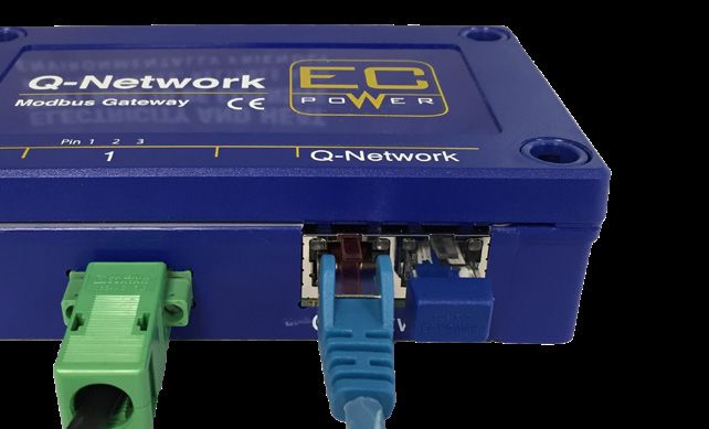
MODBUS GATEWAY DE
4. K O N F I G U R AT I O N
Nach der Einbindung des Modbus Gateways müssen die Parameter im iQ-Schalt-
schrank konfiguriert werden, bevor die XRGI®-Anlage gestartet wird.
■ Drücken Sie eine beliebige Taste am Bedienfeld, um die Displayanzeige zu
aktivieren.
■ Drücken Sie erneut eine beliebige Taste am Bedienfeld, um zum Hauptmenü 1234567890
Verbrauch:
1/1
10.1 kW
zu gelangen.
98 %
13:10:16
22.05.2019
Produktion: 9.9 kW
■ Gehen Sie mit den Tasten ▲▼auf Techniker und drücken Sie OK am Be- HAUPTMENÜ 1/1
dienfeld. Betriebsinfo.
Einstellungen
Modemanruf
Techniker
Wärmepumpe
Start/Stopp
Statistiken
■ Die Anzeige Techniker-Login erscheint. Geben Sie Ihre ID-Nr. und Passwort TECHNIKER-LOGIN 1/1
mit den Tasten ▲▼ein.
■ Bewegen Sie den Cursor mit den Tasten ▲▼auf Einloggen und drücken Sie ID-Nr.: 00000
anschließend OK am Bedienfeld. Passwort: 00000
Einloggen
■ Bewegen Sie im Technikermenü den Cursor mit den Tasten ▲▼ auf Konfi- TECHNIKERMENÜ 1/1
guration und drücken Sie OK am Bedienfeld. Log
Wartung
Q-Netz-Statistik
Konfiguration
Wärmepumpe
Produktion
IO-Status
■ Bewegen Sie den Cursor mit den Tasten ▲▼auf die Seite Modbus Gateway. MODBUS GATEWAY 5/7
■ Bewegen Sie den Cursor mit den Tasten ▲▼ auf Slave-Adresse und drücken Slave-Adresse: 2
Sie OK am Bedienfeld, um das Feld zu aktivieren.
■ Geben Sie die korrekte Adresse mit den Tasten ▲▼ ein. Die Slave-Adresse Baud rate: 9.6 K
muss im Modbus-Netzwerk einzigartig sein und im Bereich [2;247] liegen. Parity: None
Stop bits: 1
■ Drücken Sie ESC, um die Eingabe zu speichern.
■ Drücken Sie nochmals ESC, um zurück zum Menü zu gelangen.
5. ANBINDUNG AN EXTERNE SYSTEME
Externe Systeme können über das Modbus RTU mit dem RS485 Bus angebunden
01DOC1030-03 - STAND 03/2022
werden. Details zur Programmierung der externen Anbindung finden sich in der
Schnittstellenbeschreibung.
7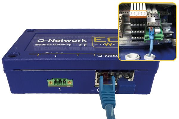
DE        MODBUS GATEWAY

                              6.       FUNKTIONSDIAGNOSE

                                       BENÖTIGTE KOMPONENTEN

                                           POS ANZAHL BESCHREIBUNG
                                           1              1         Modbus Software
                                           Ar ti k e l - N r. K 0 0 0 1 1 7
                                           2              1         USB zu RS-485 serieller Adapter
                                           3              1         Kabel, RS-485 3-polig

                                       1                                         2                    3

                                       SERIELLER ADAPT ER

                                       ■       Schließen Sie das RS-485 Kabel (3) am USB zu RS-485 serieller Adapter (2)
                                               an und verbinden Sie damit den Modbus Gateway und den Laptop.

                                       Sichern Sie bitte die korrekte Verbindung der Anschluss-Pins A, B und GND
                                       auf der Modbus-Kommunikationsseite.

                                       KONTROLLNE T Z WERK

                                       ■       Stellen Sie sicher, dass der Modbus Gateway mit dem Kontrollnetzwerk der
                                               XRGI®-Anlage verbunden ist.

                                       Bei korrekter Verbindung blinkt die orange LED Leuchte des Modbus
                                       Gateways, die die Kommunikation zur XRGI®-Anlage indiziert.

                                       M O D BUS S O F T WA R E

                                       Richten Sie die Modbus Software (2) ein - diese ist auf Anfrage erhältlich bei
                                       EC POWER.
                                       ■ Öffnen Sie die Modbus Software.
                                       ■ Wählen Sie die korrekte COM-port.
01DOC1030-03 - 03.2022

                         8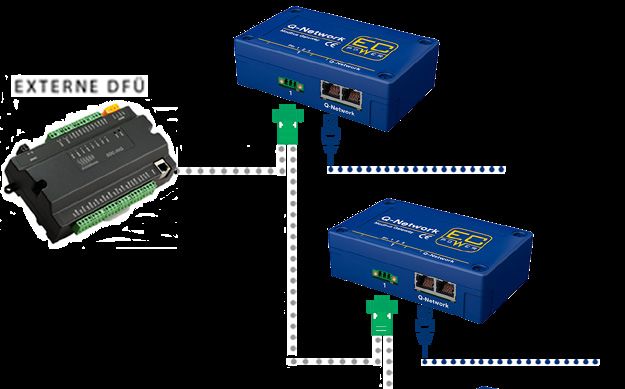
MODBUS GATEWAY   EN

1.   FUNCTION
     The Modbus Gateway is a Q-network connected device that can be added to
     provide the customer with system status information. A wide variety of infor-
     mation is available, and is continuously updated by the XRGI® system.
     The Modbus Gateway also provides a way to remote control the XRGI® system,
     which can be used e.g. by customers who want VHP ready functionality.

     The Modbus Gateway has two main functions:

     R E A D I N G I N F O R M AT I O N :
     Information is readily available (without the need for further equipment) once
     connected to the network.

     EXTERNAL CONTROL OF THE XRGI® SYSTEM:
     Once the XRGI® control software has been initialised, the operation of the XRGI®
     can be influenced by an external control. Once the external control has been in-
     itialised, the XRGI® system is operated in heat-controlled mode without external
     control in the current software version.

     The description of the interfaces includes details on the main functions.

     REQUIREMENTS FOR USE
     ■ The Modbus Gateway can only be used if the Central Control PCB with inte-
       grated modem is fitted in the iQ-Control Panel (the modem is separate with
       the old Central Control PCB). XRGI® systems with older Central Control PCBs
       can be upgraded. EC POWER provides an upgrade kit.
     ■ Software version 1.11.5 or higher is needed. A software update is required if an
       older software version is fitted in a XRGI® system.

2.   COMPONENTS & TOOLS

         COMPONEN T S

     Item no. 01ELT2067 - scope of delivery

         POS    QTY.      DESCRIPTION
         1        1       Modbus Gateway-Box
         2        1       System plug housing
         3        1       Q-Network cable 5m blue

     1                                      2                 3

     TOOLS

     No tools required
                                                                                                                01DOC1030-03 -STAND 03/2022

                                                                                                            9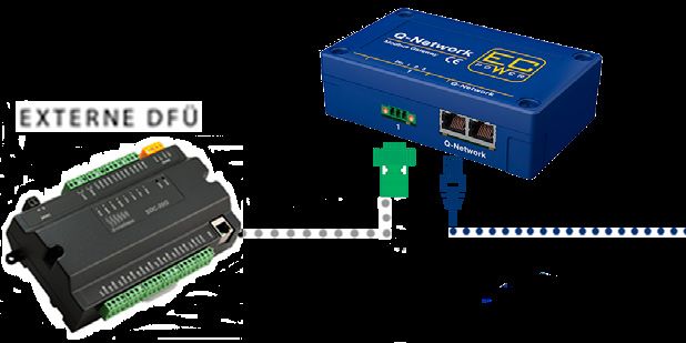
EN        MODBUS GATEWAY

                              3.       I N S TA L L AT I O N

                                       Please follow the steps in this instruction. This will make your work easier
                                       and ensure a high quality installation.

                              3.1      I N S TA L L AT I O N - O N E X R G I ® S Y S T E M

                                       The Modbus Gateway may be connected to a maximum of one XRGI® system
                                       (Q-net control network) - incorrect installation will cause errors!

                                       The Modbus Gateway must be installed on a vibration-free base.

                                       NET WORK CABLE

                                       ■   Connect the Modbus Gateway (1) to the iQ-Control Panel by the CAT6 RJ45
                                           network cable (3).
                                       ■   Connect the network cable to the RJ45 plug on the Modbus Gateway and the
                                           X100 input in the iQ-Control Panel.

                                       N E T W O R K T E R M I N AT O R

                                       ■   Unused RJ45 plugs must be covered with RJ45 (8x8) ISDN network termina-
                                           tors.

                                       SYS T EM PLUG

                                       ■   Connect the Modbus Gateway to the external system by the system plug (2).
01DOC1030-03 - 03/2022

                         10
MODBUS GATEWAY EN
3.2 I N S TA L L AT I O N - M O R E T H A N O N E X R G I ® S Y S T E M
The Modbus Gateway may be connected to a maximum of one XRGI® system
(Q-net control network). The modbus Gateway may not be used to bridge
control networks between two XRGI® systems. Multiple units may be present
on the same Modbus network. In multi-module systems, there must be installed
one Modbus Gateway per XRGI® system - incorrect installation will cause errors!
The Modbus Gateway must be installed on a vibration-free base.
NET WORK CABLE
■ Connect the Modbus Gateway (1) to the iQ-Control Panel by the CAT6 RJ45
network cable (3).
■ Connect the network cable to the RJ45 plug on the Modbus Gateway and the
X100 input in the iQ-Control Panel.
N E T W O R K T E R M I N AT O R
■ Unused RJ45 plugs must be covered with RJ45 (8x8) ISDN network termina-
tors.
SYS T EM PLUG
■ Connect the first Modbus Gateway to the external system by the system
plug (2).
■ Connect additional Modbus Gateways to each other by the system plug.
01DOC1030-03 -STAND 03/2022
11EN MODBUS GATEWAY
4. C O N F I G U R AT I O N
After installation of the Modbus Gateway the parameters must be configured in
the iQ-Control Panel prior to starting the XRGI® system.
■ Press any key on the user interface to activate the display and enter the menu.
■ Press any button on the user interface again to enter the main menu.
1234567890 1/1
Consumption 10.1 kW
98 %
13:10:16
22.05.2019
Production: 9.9 kW
■ Move the cursor to Technician by using the ▲▼buttons and press OK on MAIN MENU 1/1
the user interface. Operating info
Settings
Modem call
Technician
Heat pumps
Start/Stop
Statistics
■ The prompt Technician login appears. Enter your ID no. and password by TECHNICIAN LOGIN 1/1
using the ▲▼ buttons.
■ Move the cursor to Log in by using the ▲▼ buttons and press OK on the ID no.: 00000
user interface. Password: 00000
Log in
■ In the technician menu, move the cursor to Configuration by using the ▲▼
TECHNICIAN MENU 1/1
buttons and press OK on the user interface. Log
Maintenance
Q-network statistics
Configuration
Heat pumps
Production
IO status
■ Move the cursor to the page Modbus Gateway by using the ▲▼ buttons. MODBUS GATEWAY 5/7
■ Move the cursor to Slave-Adresse by using the ▲▼ buttons and press OK Slave-Adresse: 2
on the user interface to activate the field.
■ Enter the correct address by using the ▲▼ buttons. The slave address must Baud rate: 9.6 K
be unique on the Modbus network and in the range [2;247]. Parity: None
Stop bits: 1
■ Press ESC to save the entry.
■ Press ESC again to return to the menu.
5. CONNEC TION TO EXTERNAL SYSTEMS
External systems can be connected to the RS485 bus via the Modbus RTU.
The description of the interfaces includes details on programming the external
connection.
01DOC1030-03 - 03/2022
12MODBUS GATEWAY EN
6. FUNCTIONALITY DIAGNOSE
REQUIRED COMPONENTS
POS QTY. DESCRIPTION
1 1 Modbus software
I te m no. K 0 0 0 1 1 7
2 1 USB to RS-485 serial adaptor
3 1 Cable, RS-485 3-pole
1 2 3
SERIAL ADAPTOR
■ Connect the RS-485 cable (3) to the USB zu RS-485 serial adaptor (2) and
use it to connect the Modbus gateway and the laptop.
Please ensure the correct connection for the A, B and GND terminal pins on
the Modbus communication side.
CON T ROL NE T WOR K
■ Make sure that the Modbus Gateway is connected to the Control Network of
the XRGI® system.
For correct connection please observe the orange LED flashing on the
Modbus Gateway for communication with the XRGI® system.
M O D BUS S O F T WA R E
Set up the Modbus software (2) - this is available on request from EC POWER.
■ Open the Modbus software.
■ Choose the correct COM port. 01DOC1030-03 -STAND 03/2022
13EN MODBUS GATEWAY
A. APPENDIX
A.1 INTRODUCTION
The Modbus Gateway implements Modbus RTU on a RS485 bus.
On locations with more XRGI® systems, the Modbus Gateways connected to each XRGI® system can share the Modbus network.
A.2 RS485
The Modbus Gateway uses a galvanic isolated RS485 bus as the electric interface.
When the lid is removed, the information on the inside of the lid shows how to
connect the interface.
Terminator is active by default and is the setting used when the Modbus Gate-
way is also the bus end.
When multiple Modbus Gateways are used, only the Modbus Gateway at the bus
ends must have the terminator active. On all others, the jumper is removed to
make the terminator inactive.
C O M M U N I C AT I O N S E T T I N G S
B AU D 2400, 4800, 9600, 14400, 19200, 28800, 38400, 57600
S TA R T B I T 1
S TO P B I T 1, 2
D ATA B I T S 8
PA R I T Y None, Even, Odd
D E FAU LT A D D R E S S 1 – 100, Default 2
A.3 MODBUS FUNCTION
The following function codes are the ones supported by the Modbus Gateway.
A.3.1 F U N C T I O N 01H ( R E A D C O I L R E G I S T E R S )
This function is used to read a contiguous block of coils. The request frame specifies the starting register address and the number
of coils to be read.
The coils in the response message are packed as one coil per bit of the data field. Status is indicated as 1 = ON and 0 = OFF. The
LSB of the first data byte contains the first coil addressed in the query, the other coils following toward the high end of the byte,
and from low order to high order in the subsequent bytes.
REQUEST
F U N C T I O N CO D E 1 byte 0x01
S TA R T I N G A D D R E S S 2 byte 0x0000 to 0xFFFF
Q UA N T I T Y O F CO I L S 2 byte 1 to 2000
RESPONSE
F U N C T I O N CO D E 1 byte 0x01
BY T E CO U N T 1 byte N*
CO I L S TAT U S n byte n=N
*N = Quantity of Outputs / 8. If the remainder is different from 0, N = N+1.
01DOC1030-03 - 03/2022
14MODBUS GATEWAY EN
ERROR
F U N C T I O N CO D E 1 byte 0x81
E XC E P T I O N CO D E 1 byte 01, 02 or 03
HERE IS AN EXAMPLE OF A REQUEST TO READ COIL 2-4
REQUEST RESPONSE
FIELD NAME HEX FIELD NAME HEX
FUNCTION 01 FUNCTION 01
S TA R T I N G A D D R E S S H I 00 BY T E CO U N T 01
S TA R T I N G A D D R E S S LO 01 O U T P U T S TAT U S 2+3+4 07
Q UA N T I T Y O F O U T P U T S H I 00 -
Q UA N T I T Y O F O U T P U T S LO 03 -
In the example all coils was ON, and the result is 0x07. Coil 2 is on LSB.
The upper 5 bits are zero filled.
A.3.2 F U N C T I O N 10 H ( W R I T E H O L D I N G R E G I S T E R S )
This function is used to write a continuous block of registers. The request frame specifies the starting register address and the
number of registers to be written, followed by the data. The normal response message returns the function code, starting
address and the number of registers written.
REQUEST
F U N C T I O N CO D E 1 byte 0x10
S TA R T I N G A D D R E S S 2 byte 0x0000 to 0xFFFF
Q UA N T I T Y O F R E G I S T E R S 2 byte 0x0001 to 0x007B
BY T E CO U N T 1 byte 2 x N*
R E G I S T E R VA LU E S N* x 2 Bytes Value
RESPONSE
F U N C T I O N CO D E 1 byte 0x10
BY T E CO U N T 2 byte 0x0000 to 0xFFFF
CO I L S TAT U S 2 byte 0x0001 to 0x007B
*N = Quantity of input registers.
ERROR
F U N C T I O N CO D E 1 byte 0x90
E XC E P T I O N CO D E 1 byte 01, 02 or 03
HERE IS AN EXAMPLE OF A REQUEST TO WRITE REGISTER 1+2
REQUEST RESPONSE
FIELD NAME HEX FIELD NAME HEX
FUNCTION 10 FUNCTION 10
S TA R T I N G A D D R E S S H I 00 S TA R T I N G A D D R E S S H I 00
S TA R T I N G A D D R E S S LO 01 S TA R T I N G A D D R E S S LO 01
Q UA N T I T Y O F O U T P U T S H I 00 Q UA N T I T Y O F O U T P U T S H I 00
Q UA N T I T Y O F O U T P U T S LO 02 Q UA N T I T Y O F O U T P U T S LO 02
01DOC1030-03 -STAND 03/2022
BY T E CO U N T 04 - -
R E G I S T E R VA LU E H I 01 - -
R E G I S T E R VA LU E LO 02 - -
R E G I S T E R VA LU E H I 03 - -
R E G I S T E R VA LU E LO 04 - -
In the example, 0x0102 is written to register address 01 and 0x0304 is written to register address 02.
15EN MODBUS GATEWAY
A.4 D ATA F O R M AT R E P R E S E N TAT I O N
F O R M AT DESCRIPTION BITS RANGE
BOOL Boolean 1 0 .. 1
INT16 Integer 16 -32768 .. 32767
UI N T 1 6 Unsigned integer 16 0 .. 65535
UI N T 3 2 Unsigned long 32 0 .. 4294967295
For all formats, the byte order inside a 16 bit word is MSB at the lowest address. The word order of UINT32 is LSW followed by
MSW. BOOL is packed in 8 bit bytes.
A.5 VA R I A B L E S
A.5.1 VA R I A B L E S R E A D W I T H FU N C T I O N CO D E 1
P H YS I C A L A D D R E S S LENGTH (BITS) VARIABLE NAME DATA FORMAT DESCRIPTION
If 1, System is in ALARM
STOP. Read error code
0X0000 1 Error BOOL
register to see reason for
alarm stop.
0x0001 1 Running BOOL See section A.5.4
0x0002 1 CHP ready BOOL See section A.5.4
0x0003 1 CHP not ready BOOL See section A.5.4
0x0004 1 Odd Storage BOOL See section A.5.4
0x0005 1 Storage Sequence Found BOOL See section A.5.4
A.5.2 VA R I A B L E S R E A D W I T H FU N C T I O N CO D E 4
P H YS I C A L A D D R E S S LENGTH (WORDS) VARIABLE NAME DATA FORMAT DESCRIPTION
0X0000 1 Storage top temperature INT16 Value weight: °C x 100
0x0001 1 Storage bottom temperature INT16 Value weight: °C x 100
0x0002 1 Flow forward temperature INT16 Value weight: °C x 100
0x0003 1 Flow return temperature INT16 Value weight: °C x 100
0x0004 1 CHP to net temperature INT16 Value weight: °C x 100
0x0005 1 Outside temperature INT16 Value weight: °C x 100
0x0006 1 Current electric production UINT16 Value weight: kW x 10
0x0007 1 Cooling capacity UINT16 %
0x0008 2 Σ Electric production UINT32 kWh
0x000A 2 Σ Heat production UINT32 kWh
0x000C 1 Electric production last 15min UINT16 kWh
0x000D 1 Heat production last 15min UINT16 kWh
0x000E 2 Σ Fuel consumption UINT32 kWh
0x0010 1 Σ Running hours UINT16 Hours
0x0011 1 Σ Hours to service UINT16 Hours
0x0012 1 Error code UINT16 Number
0x0013 1 Σ Generator starts UINT16 Count.
0x0014 1 Heat control TMV temperature UINT16 Value weight: °C x 100
0x0015 1 Heat control TMK temperature UINT16 Value weight: °C x 100
0x0016 1 Heat control TLV temperature UINT16 Value weight: °C x 100
0x0017 1 Heat control TLK temperature UINT16 Value weight: °C x 100
0x0018 1 Heat control TReturn temperature UINT16 Value weight: °C x 100
0x0019 1 Heat control operational setpoint UINT16 Value weight: °C x 100
0x001A 1 Flow Master bypass temperature UINT16 Value weight: °C x 100
0x001B 1 Flow Master source temperature UINT16 Value weight: °C x 100
0x001C 1 Flow Master setpoint UINT16 Value weight: °C x 100
01DOC1030-03 - 03/2022
0x001D 1 Flow Master operational setpoint UINT16 Value weight: °C x 100
0x001E 1 Heat control engine pump level UINT16 %
0x001F 1 Heat control storage pump level UINT16 %
0x0020 1 Flow Master or Flow Control pump level UINT16 %
16MODBUS GATEWAY EN
0x0021 1 Heat control valve position UINT16 %
0x0022 1 Flow Master valve position UINT16 %
0x0023 1 Engine current heat production UINT16 Value weight: kW x 100
0x0024 1 Heat exchanger condition UINT16 Value weight: kW/K x 10
0x0025 1 Heat control separation layer UINT16 Value weight: °C x 100
0x0026 1 PU requested power UINT16 W
0x0027 1 PU LGVGP limit UINT16 W
0x0028 1 PU aim power UINT16 W
0x0029 1 PU power step position UINT16 Number
0x002A 1 PU map pressure UINT16 mBar
0x002B 1 PU fuel step position UINT16 Number
0x002C 1 PU ignition angle UINT16 Value weight: ° x 10
0x002D 1 PU water temperature UINT16 Value weight: °C x 100
0x002E 1 PU RPM UINT16 Number
0x002F 1 L1-L2 grid voltage UINT16 Volt
0x0030 1 L2-L3 grid voltage UINT16 Volt
0x0031 1 L3-L1 grid voltage UINT16 Volt
0x0032 1 Grid frequency UINT16 Value weight: Hz x 100
0x0033 1 System status UINT16 Number
A.5.3 V A R I A B L E S W R I T T E N W I T H F U N C T I O N C O D E 10
P H YS I C A L A D D R E S S LENGTH (WORDS) VARIABLE NAME DATA FORMAT DESCRIPTION
0X0000 1 VPP mode UINT16 Mode number
0x0001 1 CHP load level UINT16 %
A.5.4 V A R I A B L E E X P L A N AT I O N
ERROR If ON, the XRGI® system is in alarm stop and needs a visit from a service technician.
RUNNING If ON, XRGI® system is running.
C H P R E A DY If ON and Running = OFF, XRGI® system is expected to start when allowed by VPP mode.
If ON and Running = OFF, XRGI® system will not start even if allowed by VPP mode, but is expected
C H P N OT R E A DY
to be ready later, when e.g. cooling capacity is reestablished.
If ON, an unusual storage sensor sequence is detected. At the next stop, the system remains
O D D S TO R AG E
stopped until the storage is cold in order to detect correct storage sensor sequence.
S TO R AG E S E Q U E N C E F O U N D If ON, all storage sensors are found and the sequence has been automatically detected.
S TO R AG E TO P T E M P E R AT U R E Temperature at the first temperature sensor in the top of the storage tank.
S TO R AG E B OT TO M T E M P E R AT U R E Temperature at the last temperature sensor in the bottom of the storage tank.
Sensor after the mixing point, measuring the temperature on the water flowing into the central
F LO W F O R WA R D T E M P E R AT U R E
heating system
Sensor before the mixing point, measuring the temperature on the water coming back from the
F LO W R E T U R N T E M P E R AT U R E
central heating system
C H P TO N E T T E M P E R AT U R E Temperature available from CHP to net.
O U T S I D E T E M P E R AT U R E Temperature measured outside the building.
CURRENT ELECTRIC PRODUCTION Current measured electric production.
CO O L I N G C A PAC I T Y 0 – 100% of water in storage tank, with temperature low enough to cool the engine.
Σ ELECTRIC PRODUCTION Total measured electric production.
Σ H E AT P R O D U C T I O N Total produced heat (calculated)(not including heat production from BW 4+ / BW 8+, if relevant).
Measured electric production, averaged over a 15min period.
ELEC TRIC PRODUC TION LAST 15MIN
Value is updated according to the control panel clock at 00, 15, 30 and 45 minutes.
Heat production, averaged over a 15min period.
H E AT P R O D U C T I O N L A S T 1 5 M I N
Value is updated according to the control panel clock at 00, 15, 30 and 45 minutes.
Σ F U E L CO N S U M P T I O N Total fuel consumption (calculated).
Σ RUNNING HOURS Total running hours.
01DOC1030-03 -STAND 03/2022
Σ H O U R S TO S E R V I C E Hours to service.
If Error coil is 1, this Error Code is for the current alarm stop.
E R R O R CO D E If Error coil is 0, the Error Code is from most resent alarm stop.
Get the full list at www.service.ecpower.dk
Σ G E N E R ATO R S TA R T S Count of generator starts.
17EN MODBUS GATEWAY
When the Control panel is set up to VHP, it is possible to control the behaviour of the system with
the parameters VPP mode and CHP Load Level.
Mode 0: Heat controlled mode, production at CHP load level from storage empty until storage
full, and standby until storage empty.
Mode 1: CHP runs maximal. Starts when T2 gets cold and stops when T3 gets hot.
VPP MODE Mode 2: CHP runs minimum. Starts when T1 get cold and stops when T1 gets hot.
Mode 3: CHP stopped.
Mode 4: CHP stopped, Electric heater runs minimum, starts when T1 gets cold and starts when
T1 gets hot.
Mode 5: CHP stopped, Electric heater runs maximal, starts when second last storage sensor gets
cold and stops when last storage sensor gets hot.
When the Control panel is set up to VHP, it is possible to control the behaviour of the system with
the parameters VPP mode and CHP Load Level.
C H P LO A D L E V E L
0 - 100% of the nominal max power of the XRGI® system. If load is dropping below the XRGI®
system’s minimum load. The XRGI system will produce the minimum load.
H E AT CO N T R O L T M V T E M P E R AT U R E TMV is the current temperature of the hot water from Power Unit enters the Heat exchanger.
H E AT CO N T R O L T M K T E M P E R AT U R E TMK is the current temperature of the water to the Power Unit leaving the Heat exchanger.
H E AT CO N T R O L T LV T E M P E R AT U R E TLV is the current temperature of the hot water for domestic heating leaving the Heat exchanger.
H E AT CO N T R O L T L K T E M P E R AT U R E TLK is the current temperature of the regulated cooling water entering the Heat exchanger.
Treturn is the current temperature of the cold water from domestic heating entering the Q-Heat
H E AT CO N T R O L T R E T U R N T E M P E R AT U R E
Distributor.
H E AT CO N T R O L O P E R AT I O N A L S E T P O I N T The calculated TMV temperature the regulation is aiming for.
Temperature measured on the main string between the return temperature and the Flow tem-
F LO W M A S T E R BY PA S S T E M P E R AT U R E
perature.
F LO W M A S T E R S O U R C E T E M P E R AT U R E The source temperature measured by the Flow Master right before the pump and valve.
F LO W M A S T E R S E T P O I N T The Flow Master or Flow Control setpoint.
The Flow Master or Flow Control operative setpoint.
F LO W M A S T E R O P E R AT I O N A L S E T P O I N T Can be lower than the requested flow temperature, if the system does not have high enough
water temperature to accommodate the requested flow temperature.
H E AT CO N T R O L E N G I N E P U M P L E V E L 0-100% requested of the pump from the system.
H E AT CO N T R O L S TO R AG E P U M P L E V E L 0-100% requested of the pump from the system.
F LO W M A S T E R O R F LO W CO N T R O L
0-100% requested of the pump from the system.
PUMP LEVEL
H E AT CO N T R O L VA LV E P O S I T I O N 0-100% requested of the valve from the system.
F LO W M A S T E R VA LV E P O S I T I O N 0-100% requested of the valve from the system.
E N G I N E C U R R E N T H E AT P R O D U C T I O N Current heat production.
H E AT E XC H A N G E R CO N D I T I O N Calculated heat Exchanger condition.
Separation layer calculated by the system.
H E AT CO N T R O L S E PA R AT I O N L AY E R Separation layer represents the highest water temperature return from the domestic heating sys-
tem on which the Power Unit can run.
PU REQUESTED POWER Current requested electric power load to the Power Unit.
LGVGP (Low Grid Voltage Generator Protection) limit is a production limit that usually is the Power
Unit’s max load value, but if grid situation leads to excessive slip in the generator, the limit will
P U LG V G P L I M I T
be lowered in order to protect the generator until the slip decrease again, where after the LGVGP
limit will increase again.
PU AIM POWER The Powerload the Power Unit is actual aiming for.
PU POWER STEP POSITION Current position of the Power Unit power valve.
PU MAP PRESSURE Current manifold air pressure.
PU FUEL STEP POSITION Current position of the Power Unit fuel valve.
PU IGNITION ANGLE Current Power Unit ignition angle.
P U WAT E R T E M P E R AT U R E Current Power Unit water temperature measured inside the Power Unit.
PU RPM Current Power Unit RPM.
L 1 - L 2 G R I D V O LTAG E Current grid voltage between phase 1 and 2.
L 2 - L 3 G R I D V O LTAG E Current grid voltage between phase 2 and 3.
L 3 - L 1 G R I D V O LTAG E Current grid voltage between phase 3 and 1.
GRID FREQUENCY Current grid frequency.
S YS T E M S TAT U S Current system status, see online manual on service.ecpower.dk.
For more information on Modbus protocol: www.modbus.org
01DOC1030-03 - 03/2022
18MODBUS GATEWAY DE
In der Modbus-Software steht nur Englisch als Sprache zur Verfügung. Im Folgenden finden Sie aber als Hilfestellung eine Über-
setzung der Erklärungen zu den Variablen (Appendix A.4 - A.5).
A.4 D AT E N F O R M AT R E P R Ä S E N TAT I O N
F O R M AT BESCHREIBUNG BITS BEREICH
BOOL Boolean 1 0 .. 1
INT16 Integer 16 -32768 .. 32767
UI N T 1 6 Unsigned integer 16 0 .. 65535
UI N T 3 2 Unsigned long 32 0 .. 4294967295
Bei allen Formaten ist die Bytereihenfolge innerhalb eines 16-Bit-Worts das MSB an der niedrigsten Adresse. Die Wortreihenfolge
von UINT32 ist LSW gefolgt von MSW. BOOL wird in 8-Bit-Bytes gepackt.
A.5 VA R I A B L E N
A.5.1 G E L E S E N E VA R I A B L E N M I T FU N K T I O N S CO D E 1
P H YS I S C H E A D R E S S E LÄNGE (BITS) VARIABLENNAME DATENFORMAT BESCHREIBUNG
Wenn 1, befindet sich das
System im ALARM STOP.
Lesen Sie das Fehlercode-
0X0000 1 Error BOOL
register, um den Grund
für den Alarmstopp zu
erfahren.
0x0001 1 Running BOOL Siehe Abschnitt A.5.4
0x0002 1 CHP ready BOOL Siehe Abschnitt A.5.4
0x0003 1 CHP not ready BOOL Siehe Abschnitt A.5.4
0x0004 1 Odd Storage BOOL Siehe Abschnitt A.5.4
0x0005 1 Storage Sequence Found BOOL Siehe Abschnitt A.5.4
A.5.2 G E L E S E N E VA R I A B L E N M I T FU N K T I O N S CO D E 4
P H YS I C A L A D D R E S S LENGTH (WORDS) VARIABLE NAME DATA FORMAT BESCHREIBUNG
0X0000 1 Storage top temperature INT16 Anzeigewert: °C x 100
0x0001 1 Storage bottom temperature INT16 Anzeigewert: °C x 100
0x0002 1 Flow forward temperature INT16 Anzeigewert: °C x 100
0x0003 1 Flow return temperature INT16 Anzeigewert: °C x 100
0x0004 1 CHP to net temperature INT16 Anzeigewert: °C x 100
0x0005 1 Outside temperature INT16 Anzeigewert: °C x 100
0x0006 1 Current electric production UINT16 Anzeigewert: kW x 10
0x0007 1 Cooling capacity UINT16 %
0x0008 2 Σ Electric production UINT32 kWh
0x000A 2 Σ Heat production UINT32 kWh
0x000C 1 Electric production last 15min UINT16 kWh
0x000D 1 Heat production last 15min UINT16 kWh
0x000E 2 Σ Fuel consumption UINT32 kWh
0x0010 1 Σ Running hours UINT16 Stunden
0x0011 1 Σ Hours to service UINT16 Stunden
0x0012 1 Error code UINT16 Nummer
0x0013 1 Σ Generator starts UINT16 Anzahl
0x0014 1 Heat control TMV temperature UINT16 Anzeigewert: °C x 100
0x0015 1 Heat control TMK temperature UINT16 Anzeigewert: °C x 100
0x0016 1 Heat control TLV temperature UINT16 Anzeigewert: °C x 100
0x0017 1 Heat control TLK temperature UINT16 Anzeigewert: °C x 100
0x0018 1 Heat control TReturn temperature UINT16 Anzeigewert: °C x 100
01DOC1030-03 - STAND 03/2022
0x0019 1 Heat control operational setpoint UINT16 Anzeigewert: °C x 100
0x001A 1 Flow Master bypass temperature UINT16 Anzeigewert: °C x 100
0x001B 1 Flow Master source temperature UINT16 Anzeigewert: °C x 100
0x001C 1 Flow Master setpoint UINT16 Anzeigewert: °C x 100
0x001D 1 Flow Master operational setpoint UINT16 Anzeigewert: °C x 100
0x001E 1 Heat control engine pump level UINT16 %
0x001F 1 Heat control storage pump level UINT16 %
0x0020 1 Flow Master or Flow Control pump level UINT16 %
19DE MODBUS GATEWAY
0x0021 1 Heat control valve position UINT16 %
0x0022 1 Flow Master valve position UINT16 %
0x0023 1 Engine current heat production UINT16 Anzeigewert: kW x 100
0x0024 1 Heat exchanger condition UINT16 Anzeigewert: kW/K x 10
0x0025 1 Heat control separation layer UINT16 Anzeigewert: °C x 100
0x0026 1 PU requested power UINT16 W
0x0027 1 PU LGVGP limit UINT16 W
0x0028 1 PU aim power UINT16 W
0x0029 1 PU power step position UINT16 Nummer
0x002A 1 PU map pressure UINT16 mBar
0x002B 1 PU fuel step position UINT16 Nummer
0x002C 1 PU ignition angle UINT16 Anzeigewert: ° x 10
0x002D 1 PU water temperature UINT16 Anzeigewert: °C x 100
0x002E 1 PU RPM UINT16 Nummer
0x002F 1 L1-L2 grid voltage UINT16 Volt
0x0030 1 L2-L3 grid voltage UINT16 Volt
0x0031 1 L3-L1 grid voltage UINT16 Volt
0x0032 1 Grid frequency UINT16 Anzeigewert: Hz x 100
0x0033 1 System status UINT16 Nummer
A.5.3 G E S C H R I E B E N E V A R I A B L E N M I T F U N K T I O N S C O D E 10
P H YS I S C H E A D R E S S E LÄNGE (WÖRTER) VARIABLENNAME DATENFORMAT BESCHREIBUNG
0X0000 1 VPP mode UINT16 Modusnummer
0x0001 1 CHP load level UINT16 %
A.5.4 E R K L Ä R U N G D E R VA R I A B L E N
Wenn ON, befindet sich das XRGI®-System im Alarmzustand und benötigt den Besuch eines Ser-
ERROR
vicetechnikers.
RUNNING Wenn ON, XRGI®-System läuft.
Wenn ON und Laufend = OFF, XRGI®-System wird erwartet zu starten, wenn der VPP-Modus dies
C H P R E A DY
zulässt.
Wenn ON und Laufend = OFF, XRGI®-System wird nicht gestartet, auch wenn der VPP-Modus dies
C H P N OT R E A DY
zulässt, sondern voraussichtlich erst später, wenn z. B. die Kühlkapazität wiederhergestellt ist.
Wenn ON, wird eine ungewöhnliche Speicherfühlerfolge erkannt und das System bleibt beim
O D D S TO R AG E nächsten Stopp stehen, bis der Speicher kalt ist, um die korrekte Speicherfühlerfolge zu erken-
nen.
S TO R AG E S E Q U E N C E F O U N D Wenn ON, sind alle Speicherfühler gefunden und die Sequenz ist automatisch erkannt.
S TO R AG E TO P T E M P E R AT U R E Temperatur am ersten Temperaturfühler im oberen Teil des Wärmespeichers.
S TO R AG E B OT TO M T E M P E R AT U R E Temperatur am letzten Temperaturfühler im unteren Teil des Wärmespeichers.
Temperaturfühler nach dem Mischpunkt, der die Temperatur des in die Kundenanlage fließenden
F LO W F O R WA R D T E M P E R AT U R E
Heizungswassers misst.
Temperaturfühler vor dem Mischpunkt, der die Temperatur des von der Kundenanlage zurück-
F LO W R E T U R N T E M P E R AT U R E
kommenden Heizungswassers misst.
C H P TO N E T T E M P E R AT U R E Verfügbare Temperatur vom BHKW zum Netz.
O U T S I D E T E M P E R AT U R E Gemessene Temperatur außerhalb des Gebäudes.
CURRENT ELECTRIC PRODUCTION Aktuelle gemessene Stromerzeugung.
0 – 100% Wasser im Wärmespeicher, mit einer Temperatur, die niedrig genug ist, um den Motor
CO O L I N G C A PAC I T Y
zu kühlen.
Σ ELECTRIC PRODUCTION Gemessene elektrische Gesamtstromerzeugung.
Gesamte Wärmeerzeugung (berechnet)(evtl. Wärmeerzeugung von BW 4+ / BW 8+ nicht
Σ H E AT P R O D U C T I O N
enthalten).
Gemessene Stromerzeugung, gemittelt über einen Zeitraum von 15 Minuten. Der Wert wird ent-
ELEC TRIC PRODUC TION LAST 15MIN
sprechend der Uhr des Bedienfelds um 00, 15, 30 und 45 Minuten aktualisiert.
Wärmeerzeugung, gemittelt über einen Zeitraum von 15 Minuten. Der Wert wird entsprechend
H E AT P R O D U C T I O N L A S T 1 5 M I N
der Uhr des Bedienfelds um 00, 15, 30 und 45 Minuten aktualisiert.
01DOC1030-03 - 03.2022
Σ F U E L CO N S U M P T I O N Gesamter Kraftstoffverbrauch (berechnet).
Σ RUNNING HOURS Betriebsstunden insgesamt.
Σ H O U R S TO S E R V I C E Stunden bis zum Wartungseinsatz.
Wenn Fehler-Coil 1 ist, bezieht sich dieser Fehlercode auf den aktuellen Alarmstopp.
E R R O R CO D E Wenn Fehler-Coil 0 ist, ist der Fehlercode vom letzten Alarmstopp.
Die vollständige Liste finden Sie unter: service.ecpower.dk
Σ G E N E R ATO R S TA R T S Anzahl der Generatorstarts.
20MODBUS GATEWAY DE
Wenn der Schaltschrank auf VHP eingestellt ist, kann das Verhalten des Systems mit den Parame-
tern VPP-Modus und BHKW-Lastniveau gesteuert werden.
Modus 0: Wärmegeführter Modus, Erzeugung auf BHKW-Lastniveau von Speicher leer bis Speich-
er voll; und Standby bis Speicher leer.
Modus 1: BHKW läuft maximal. Startet, wenn T2 kalt wird und stoppt, wenn T3 warm wird.
VPP MODE Modus 2: BHKW läuft minimal. Startet, wenn T1 kalt wird und stoppt, wenn T1 warm wird.
Modus 3: BHKW gestoppt.
Modus 4: BHKW gestoppt, Elektroheizung läuft minimal, startet, wenn T1 kalt wird, und stoppt,
wenn T1 warm wird.
Modus 5: BHKW gestoppt, Elektroheizung läuft maximal, startet, wenn der vorletzte Speicherfühler
kalt wird und stoppt, wenn der letzte Speicherfühler warm wird.
Wenn der Schaltschrank auf VHP eingestellt ist, kann das Verhalten des Systems mit den
Parametern VPP-Modus und BHKW-Lastniveau gesteuert werden.
C H P LO A D L E V E L
0 - 100% der maximalen Nennleistung des XRGI®-Systems. Wenn die Last unter die Mindestlast
des XRGI®-Systems sinkt. Das XRGI®-System wird die Mindestlast erzeugen.
TMV ist die aktuelle Temperatur des Warmwassers, das von der Power Unit in den Wärmetauscher
H E AT CO N T R O L T M V T E M P E R AT U R E
gelangt.
TMK ist die aktuelle Temperatur des aus dem Wärmetauscher austretenden Warmwassers für die
H E AT CO N T R O L T M K T E M P E R AT U R E
Power Unit.
TLV ist die aktuelle Temperatur des aus dem Wärmetauscher austretenden Warmwassers für die
H E AT CO N T R O L T LV T E M P E R AT U R E
Hausheizung.
H E AT CO N T R O L T L K T E M P E R AT U R E TLK ist die aktuelle Temperatur des regulierten Kühlwassers, das in den Wärmetauscher eintritt.
Rücklauftemperatur (Treturn) ist die aktuelle Temperatur des Kaltwassers aus der Hausheizung,
H E AT CO N T R O L T R E T U R N T E M P E R AT U R E
das in den Q-Wärmeverteiler eintritt.
H E AT CO N T R O L O P E R AT I O N A L S E T P O I N T Die berechnete TMV-Temperatur, die durch die Regelung angestrebt wird.
Am Hauptstrang gemessene Temperatur zwischen der Rücklauftemperatur und der Vorlauftem-
F LO W M A S T E R BY PA S S T E M P E R AT U R E
peratur.
F LO W M A S T E R S O U R C E T E M P E R AT U R E Die vom Flow Master gemessene Quelltemperatur unmittelbar vor der Pumpe und dem Ventil.
F LO W M A S T E R S E T P O I N T Der Sollwert des Flow Master oder Flow Control.
Der operative Sollwert des Flow Master oder Flow Control.
F LO W M A S T E R O P E R AT I O N A L S E T P O I N T Kann niedriger als die gewünschte Vorlauftemperatur sein, wenn die Wassertemperatur im Sys-
tem nicht hoch genug ist, um die gewünschte Vorlauftemperatur zu erreichen.
H E AT CO N T R O L E N G I N E P U M P L E V E L 0-100% der vom System angeforderten Pumpenleistung.
H E AT CO N T R O L S TO R AG E P U M P L E V E L 0-100% der vom System angeforderten Pumpenleistung.
F LO W M A S T E R O R F LO W CO N T R O L
0-100% der vom System angeforderten Pumpenleistung.
PUMP LEVEL
H E AT CO N T R O L VA LV E P O S I T I O N 0-100% der vom System angeforderten Ventilleistung.
F LO W M A S T E R VA LV E P O S I T I O N 0-100% der vom System angeforderten Ventilleistung.
E N G I N E C U R R E N T H E AT P R O D U C T I O N Aktuelle Wärmeerzeugung.
H E AT E XC H A N G E R CO N D I T I O N Berechneter Zustand des Wärmetauschers.
Vom System berechnete Trennschicht.
H E AT CO N T R O L S E PA R AT I O N L AY E R Die Trennschicht stellt die höchste von der Hausheizung zurückgeführte Wassertemperatur dar,
mit der die Power Unit betrieben werden kann.
PU REQUESTED POWER Aktuell angeforderte elektrische Leistung für die Power Unit.
Der LGVGP-Grenzwert (Generatorschutz bei niedriger Netzspannung) ist ein Produktionsgrenz-
wert, der normalerweise der maximale Lastwert der Power Unit ist. Wenn jedoch die Netzsitua-
P U LG V G P L I M I T tion zu einem übermäßigen Schlupf des Generators führt, wird der Grenzwert gesenkt, um den
Generator zu schützen, bis der Schlupf wieder abnimmt, woraufhin der LGVGP-Grenzwert wieder
erhöht wird.
PU AIM POWER Die Leistungslast, die die Power Unit anstrebt.
PU POWER STEP POSITION Aktuelle Position des Power-Ventils der Power Unit.
PU MAP PRESSURE Aktueller Ladeluftdruck.
PU FUEL STEP POSITION Aktuelle Position des Fuel-Ventils der Power Unit.
PU IGNITION ANGLE Aktueller Zündwinkel der Power Unit.
P U WAT E R T E M P E R AT U R E Aktuelle Wassertemperatur der Power Unit, gemessen im Inneren der Power Unit.
PU RPM Aktuelle Drehzahl der Power Unit.
L 1 - L 2 G R I D V O LTAG E Aktuelle Netzspannung zwischen Phase 1 und 2.
L 2 - L 3 G R I D V O LTAG E Aktuelle Netzspannung zwischen Phase 2 und 3.
L 3 - L 1 G R I D V O LTAG E Aktuelle Netzspannung zwischen Phase 3 und 1.
GRID FREQUENCY Aktuelle Netzfrequenz.
01DOC1030-03 - STAND 03/2022
S YS T E M S TAT U S Aktueller Systemstatus, siehe Online-Handbuch auf service.ecpower.dk.
Weitere Informationen zum Modbus-Protokoll finden Sie unter: www.modbus.org
21Q-NETWORK M O D B U S G AT E WAY 0 1 E L T 2 0 6 7 M A N U A L 01DOC1030-03 03.2022
Sie können auch lesen


