REMOTEACCESS-CPU - INSTALLATIONSANLEITUNG EN INSTALLATION GUIDE - GUNTERMANN & DRUNCK GMBH
←
→
Transkription von Seiteninhalten
Wenn Ihr Browser die Seite nicht korrekt rendert, bitte, lesen Sie den Inhalt der Seite unten
Guntermann & Drunck GmbH
www.gdsys.de

RemoteAccess-CPU

 DE     Installationsanleitung
 EN     Installation Guide

A9100373-1.00
Zu dieser Dokumentation Diese Dokumentation wurde mit größter Sorgfalt erstellt und nach dem Stand der Technik auf Korrektheit überprüft. Für die Qualität, Leistungsfähigkeit sowie Marktgängigkeit des G&D-Produkts zu einem bestimmten Zweck, der von dem durch die Produktbeschreibung abgedeck- ten Leistungsumfang abweicht, übernimmt G&D weder ausdrücklich noch still- schweigend die Gewähr oder Verantwortung. Für Schäden, die sich direkt oder indirekt aus dem Gebrauch der Dokumentation ergeben, sowie für beiläufige Schäden oder Folgeschäden ist G&D nur im Falle des Vorsatzes oder der groben Fahrlässigkeit verantwortlich. Gewährleistungsausschluss G&D übernimmt keine Gewährleistung für Geräte, die nicht bestimmungsgemäß eingesetzt wurden. nicht autorisiert repariert oder modifiziert wurden. schwere äußere Beschädigungen aufweisen, welche nicht bei Lieferungserhalt angezeigt wurden. durch Fremdzubehör beschädigt wurden. G&D haftet nicht für Folgeschäden jeglicher Art, die möglicherweise durch den Einsatz der Produkte entstehen können. Warenzeichennachweis Alle Produkt- und Markennamen, die in diesem Handbuch oder in den übrigen Dokumentationen zu Ihrem G&D-Produkt genannt werden, sind Warenzeichen oder eingetragene Warenzeichen der entsprechenden Rechtsinhaber. Impressum © Guntermann & Drunck GmbH 2020. Alle Rechte vorbehalten. Version 1.00 – 07.10.2020 Guntermann & Drunck GmbH Obere Leimbach 9 57074 Siegen Germany Telefon +49 (0) 271 23872-0 Telefax +49 (0) 271 23872-120 http://www.gdsys.de sales@gdsys.de i · RemoteAccess-CPU-Serie
FCC Statement
Deutsch
The devices named in this manual comply with Part 15 of the FCC Rules. Opera-
tion is subject to the following two conditions: (1) the devices may not cause harm-
ful interference, and (2) the devices must accept any interference received, including
interference that may cause undesired operation.
HINWEIS: This equipment has been tested and found to comply with the limits for
a Class B digital device, pursuant to Part 15 of the FCC Rules. These limits are
designed to provide reasonable protection against harmful interference in a resi-
dential installation.
This equipment generates, uses and can radiate radio frequency energy and, if not
installed and used in accordance with the instructions, may cause harmful interfe-
rence to radio communications. However, there is no guarantee that interference
will not occur in a particular installation.
If this equipment does cause harmful interference to radio or television reception,
which can be deter-mined by turning the equipment off and on, the user is
encouraged to try to correct the interference by one or more of the following mea-
sures:
Reorient or relocate the receiving antenna.
Increase the separation between the equipment and receiver.
Connect the equipment into an outlet on a circuit different from that
to which the receiver is connected.
Consult the dealer or an experienced radio/TV technician for help.
RemoteAccess-CPU-Serie · iiInhaltsverzeichnis Inhaltsverzeichnis Sicherheitshinweise .......................................................................................... 1 Kapitel 1: Target-Module Das Target-Modul »RemoteAccess-CPU« ........................................................ 5 Das Target-Modul »RemoteAccess-CPU-Fiber« ............................................. 10 Kapitel 2: Konfiguration Erstkonfiguration der Netzwerkeinstellungen ................................................. 17 Integration in das KVM-Matrixsystem ........................................................... 20 iii · RemoteAccess-CPU-Serie
Sicherheitshinweise

Sicherheitshinweise

                                                                                          Deutsch
Bitte lesen Sie die folgenden Sicherheitshinweise aufmerksam durch, bevor Sie das
G&D-Produkt in Betrieb nehmen. Die Hinweise helfen Schäden am Produkt zu ver-
meiden und möglichen Verletzungen vorzubeugen.
Halten Sie diese Sicherheitshinweise für alle Personen griffbereit, die dieses Produkt
benutzen werden.
Befolgen Sie alle Warnungen oder Bedienungshinweise, die sich am Gerät oder in
dieser Bedienungsanleitung befinden.

       Trennen Sie alle Spannungsversorgungen

 VORSICHT: Risiko elektrischer Schläge!

Stellen Sie vor der Installation sicher, dass das Gerät von allen Stromquellen getrennt
ist. Ziehen Sie alle Netzstecker und alle Spannungsversorgungen am Gerät ab.

       Disconnect all power sources

 CAUTION: Shock hazard!

Before installation, ensure that the device has been disconnected from all power
sources. Disconnect all power plugs and all power supplies of the device.

       Débranchez toutes les sources d'alimentation

 ATTENTION: Risque de choc électrique!

Avant l'installation, assurez-vous que l'appareil a été débranché de toutes les sources
d'alimentation. Débranchez toutes les fiches d'alimentation et toutes les alimenta-
tions électrique de l'appareil.

   Vorsicht vor Stromschlägen
Um das Risiko eines Stromschlags zu vermeiden, sollten Sie das Gerät nicht öffnen oder
Abdeckungen entfernen. Im Servicefall wenden Sie sich bitte an unsere Techniker.

                                                          RemoteAccess-CPU-Serie · 1
Sicherheitshinweise Ständigen Zugang zu den Netzsteckern der Geräte sicherstellen Achten Sie bei der Installation der Geräte darauf, dass die Netzstecker der Geräte jederzeit zugänglich bleiben. ! Lüftungsöffnungen nicht verdecken Bei Gerätevarianten mit Lüftungsöffnungen ist eine Verdeckung der Lüftungsöff- nungen unbedingt zu vermeiden. ! Stolperfallen vermeiden Vermeiden Sie bei der Verlegung der Kabel Stolperfallen. Geerdete Spannungsquelle verwenden Betreiben Sie dieses Gerät nur an einer geerdeten Spannungsquelle. Verwenden Sie ausschließlich das G&D-Netzteil Betreiben Sie dieses Gerät nur mit dem mitgelieferten oder in der Bedienungsanlei- tung aufgeführten Netzteil. ! Betreiben Sie das Gerät ausschließlich im vorgesehenen Einsatzbereich Die Geräte sind für eine Verwendung im Innenbereich ausgelegt. Vermeiden Sie extreme Kälte, Hitze oder Feuchtigkeit. 2 · RemoteAccess-CPU-Serie
Sicherheitshinweise
Hinweise zum Umgang mit Lithium-Knopfzellen
Deutsch
Dieses Produkt enthält eine Lithium-Knopfzelle. Ein Austausch durch den
Anwender ist nicht vorgesehen!
VORSICHT: Es besteht Explosionsgefahr, wenn die Batterie durch einen falschen
Batterie-Typ ersetzt wird.
Entsorgen Sie gebrauchte Batterien umweltgerecht. Gebrauchte Batterien dürfen
nicht in den Hausmüll geworfen werden.
Beachten Sie die gültigen Vorschriften zur Entsorgung elektronischer Produkte.
This product contains a lithium button cell. It is not intended to be replaced
by the user!
CAUTION: Risk of explosion if the battery is replaced by an incorrect battery type.
Dispose of used batteries in an environmentally friendly manner. Do not dispose
of batteries in municipal waste.
Check local regulations for the disposal of electronic products.
Ce produit contient une batterie au lithium. Il n'est pas prévu que l'utilisateur
remplace cette batterie.
ATTENTION: Il y a danger d'explosion s'il y a remplacement incorrect de la batterie.
Mettre au rebut les batteries usagées conformêment aux instructions du fabricant
et de manière écologique. Les batteries usagées ne doivent pas être jetées dans les
ordures ménagères.
Respectez les prescriptions valables pour l'élimination des produits électroniques.
RemoteAccess-CPU-Serie · 3Sicherheitshinweise
Besondere Hinweise zum Umgang mit Laser-Technologie
Die Fiber der RemoteAccess-CPU-Serie verwenden Baugruppen mit Laser-Technolo-
gie, die der Laser-Klasse 1 oder besser entsprechen.
Sie erfüllen dabei die Richtlinien gemäß EN 60825-1:2014 sowie U.S. CFR 1040.10 und
1040.11.
Unsichtbare Laserstrahlung,
LASER KLASSE 1 nicht direkt mit optischen Complies with 21 CFR
EN 60825-1:2014 Instrumenten betrachten 1040.10 and 1040.11
Invisible laser beam, avoid
Class 1 Laser Product direct eye exposure with Complies with 21 CFR
EN 60825-1:2014 optical instruments 1040.10 and 1040.11
Laser invisible, évitez
Produit laser de classe 1 l'exposition directe des yeux Est conforme à 21 CFR
EN 60825-1:2014 avec des instruments optiques 1040.10 et 1040.11
Beachten Sie zum sicheren Umgang mit der Laser-Technologie folgende Hinweise:
! Blickkontakt mit dem unsichtbaren Laserstrahl vermeiden
Betrachten Sie die unsichtbare Laserstrahlung niemals mit optischen Instrumenten!
! Optische Anschlüsse stets verbinden oder mit Schutzkappen abdecken
Decken Sie die optischen Anschlüsse der Transmission-Buchsen und die Kabelstecker
stets mit einer Schutzkappe ab, wenn diese nicht verbunden sind.
! Ausschließlich von G&D zertifizierte Übertragungsmodule verwenden
Es ist nicht zulässig, Lichtwellen-Module zu verwenden, die nicht der Laser-
Klasse 1 gemäß EN 60825-1:2014 entsprechen. Durch die Verwendung solcher
Module kann die Einhaltung von Vorschriften und Empfehlungen zum sicheren
Umgang mit Laser-Technologie nicht sichergestellt werden.
Die Gewährleistung zur Erfüllung aller einschlägigen Bestimmungen kann nur in
der Gesamtheit der Originalkomponenten gegeben werden. Aus diesem Grund ist
der Betrieb der Geräte ausschließlich mit solchen Übertragungsmodulen zulässig,
die von G&D zertifiziert wurden.
4 · RemoteAccess-CPU-SerieA Target-Module
Deutsch
Das Target-Modul
»RemoteAccess-CPU«
Mit dem Target-Modul RemoteAccess-CPU integrieren Sie über ein Netzwerk erreich-
bare virtuelle Computer in einen digitalen Matrixswitch der ControlCenter-Compact-
oder ControlCenter-Digital-Serie.
Die Netzwerkverbindung mit den virtuellen Computern kann wahlweise über das
SSH-, VNC -oder RDP-Protokoll erfolgen.
Nach der Konfiguration einer beliebigen Anzahl an virtuellen Computern kann der
Zugriff auf einen der virtuellen Computer direkt über das KVM-Matrixsystem erfol-
gen.
HINWEIS: Jedes Target-Modul RemoteAccess-CPU kann eine Verbindung zu einem
virtuellen Computer herstellen.
Falls mehrere, gleichzeitige Verbindungen zu verschiedenen virtuellen Computern
innerhalb des KVM-Matrixsystems erforderlich sind, benötigen Sie die entspre-
chende Anzahl an Target-Modulen der RemoteAccess-CPU-Serie.
Die virtuellen Computer werden, wie auch die weiteren Targets, in das OSD und
Bedienkonzept des Matrixswitches integriert: Sie schalten sich daher wie üblich
über das Select-Menü im OSD auf einen virtuellen Computer auf und können auch
Komfortfunktionen wie Push-Get, Multi-User-Zugriff oder CrossDisplay-Switching mit den
virtuellen Computern benutzen.
RemoteAccess-CPU-Serie · 5Das Target-Modul »RemoteAccess-CPU« Die Netzwerkverbindung zu den virtuellen Computern erfolgt über eine Ethernet- Netzwerkschnittstelle (idealerweise: Gigabit-Ethernet). WICHTIG: Die Dauer des Verbindungsaufbaus sowie die Performance der Verbin- dung zum virtuellen Computer hängen maßgeblich von der Geschwindigkeit und Qualität der Netzwerkverbindung zum virtuellen Computer ab! Die maximal darstellbare Desktop-Auflösung des virtuellen Computers beträgt 2560 × 1600 Bildpunkte. Stellen Sie sicher, dass sowohl das eingesetzte Arbeitsplatz- modul als auch der Monitor die gewünschte Auflösung unterstützen. Über das RDP-Protokoll wird die Übertragung des Embedded-Audio-Signals via DisplayPort™-Kabel unterstützt. Verwenden Sie zur Wiedergabe des Embedded- Audio-Signals ein kompatibles DisplayPort-Arbeitsplatzmodul und einen kompatib- len Monitor. Lieferumfang 1 × Target-Modul RemoteAccess-CPU 1 × Netzteil (12V/2A) 1 × Stromversorgungskabel 1 × Installationsanleitung Erforderliches Zubehör 1 × Twisted-Pair-Kabel der Kategorie 5e (oder höher) zum Anschluss des Target-Moduls an einen Matrixswitch 6 · RemoteAccess-CPU-Serie
Das Target-Modul »RemoteAccess-CPU«
Installation
Deutsch
HINWEIS: Platzieren Sie das Target-Modul ausschließlich aufrecht (s. Skizze
unten) oder um 90° nach links bzw. rechts geneigt.
HINWEIS: Der Lüfter saugt vorne die Außenluft in das Gerät. An den hinteren Lüf-
tungsöffnen wird die warme Luft ausgestoßen.
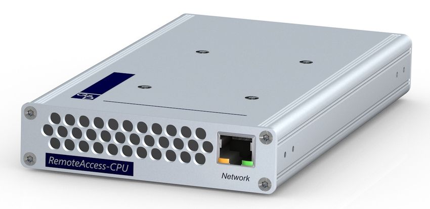
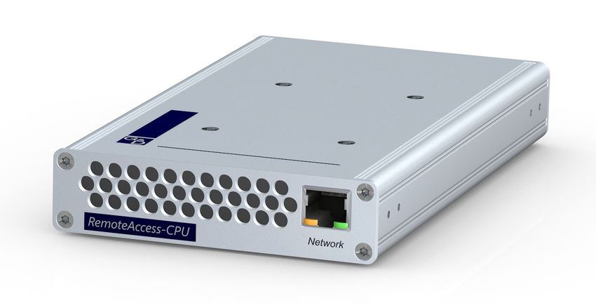
Anschluss des Target-Computers
Network
Network: Stecken Sie ein Twisted-Pair-Kabel der Kategorie 5e (oder höher) ein.
Das andere Ende des Kabels ist mit dem Netzwerk (Gigabit-Ethernet) zu verbinden.
WICHTIG: Stellen Sie sicher, dass alle virtuellen Computer über diese Schnittstelle
erreichbar sind.
Verbindung zum Matrixswitch
Power
Trans. Service Power In
Trans.: Verbinden Sie die Schnittstelle mit einem Dynamic Port (RJ45) des Matrix-
switches. Verwenden Sie hierzu eine Twisted-Pair-Verkabelung der Kategorie 5e
(oder höher).
Stromversorgung
Power In: Stecken Sie das Anschlusskabel des Netzteils in diese Schnittstelle.
Verbinden Sie das Stromversorgungskabel mit dem Netzteil und einer Netzsteckdose.
RemoteAccess-CPU-Serie · 7Das Target-Modul »RemoteAccess-CPU«
Statusanzeigen
Die Power-LED an der Rückseite des Target-Moduls signalisiert den Status der
Stromversorgung und hilft mit der Ident.-LED-Funktion beim Auffinden des Geräts
in großen Installation:
LED Status Bedeutung
Power leuchtet Das externe Netzteil ist angeschlossen und eine Spannung von 12 Volt
grün verfügbar.
leuchtet Das externe Netzteil ist angeschlossen und eine Spannung von 12 Volt
blau verfügbar.
Die Ident.-LED zum schnellen Identifizieren des Geräts wurde
(beispielsweise über die Webapplikation) aktiviert.
aus Das externe Netzteil ist nicht (korrekt) angeschlossen.
Das Blinken der Transmission-LEDs an der Rückseite signalisiert folgende Betriebs-
zustände der jeweiligen Verbindung:
LED Status Bedeutung
links aus Verbindung zur Gegenstelle nicht hergestellt
leuchtet Kommunikation mit G&D Gegenstelle hergestellt
gelb
blinkt Verbindung zu einer Gegenstelle hergestellt
gelb
rechts aus kein Endgerät aufgeschaltet
leuchtet Endgerät aufgeschaltet
grün
Das Blinken der Network-LEDs an der Frontseite signalisiert folgende Betriebszu-
stände der jeweiligen Verbindung:
LED Status Bedeutung
links aus keine Netzwerkaktivität
leuchtet Netzwerkverbindung aufgebaut
gelb
flackert Netzwerkaktivität findet statt
gelb
rechts aus keine Netzwerkverbindung
leuchtet Netzwerkverbindung mit 10 oder 100 Mbit/s aufgebaut
gelb
leuchtet Netzwerkverbindung aufgebaut mit 1 Gbit/s
grün
8 · RemoteAccess-CPU-SerieDas Target-Modul »RemoteAccess-CPU«
Technische Daten
Deutsch
REMOTEACCESS-CPU
Video unterstützte 2560×1600/60Hz/VESA CVT-RB
Auflösungen: 2560×1440/60Hz/VESA CVT-RB
1920×1200/60Hz/VESA CVT-RB
1920×1080x60Hz/CTA-861-D
1600×1200/60Hz/VESA DMT
1680×1050/60Hz/VESA CVT
1280×1024/60Hz/VESA DMT
1024×768/60Hz/VESA DMT
Farbtiefe: 24 Bit
Videobandbreite: 25 bis 330 MP/s
Audio Übertragungsart: 2-Kanal-LPCM, stereo
DisplayPort Digital
Auflösungen: 16/20/24 bit
Abtastraten: bis 48 kHz
Datenübertragung zum Schnittstelle: 1 × RJ45-Buchse
Matrixswitch
Übertragungslänge: max. 140 Meter
Datenübertragung zu Schnittstelle: 1 × RJ45-Buchse
den Terminalservern
Datenraten: 10 MBit/s, 100 MBit/s, 1000 MBit/s
unterstützte Protokolle: SSH, RDP, VNC
Stromversorgung Typ: Tischnetzteil (12 V/2 A)
Anschluss: 1 × Mini-DIN 4-Buchse
Stromaufnahme: max. 1,2 A
Gehäuse Material: Aluminium eloxiert
Maße (B × H × T): 105 × 26 × 184 mm
Gewicht: ca. 400 g
Einsatzumgebung Temperatur: +5 °C bis +45 °C
Luftfeuchte: 20 % bis 80 %, nicht kondensierend
Lagerumgebung Temperatur: -20 °C bis +55 °C
Luftfeuchte: 15 % bis 85 %, nicht kondensierend
Konformität CE, EAC, RoHS
RemoteAccess-CPU-Serie · 9Das Target-Modul »RemoteAccess-CPU-Fiber« Das Target-Modul »RemoteAccess-CPU-Fiber« Mit dem Target-Modul RemoteAccess-CPU-Fiber integrieren Sie über ein Netzwerk erreichbare virtuelle Computer in einen digitalen Matrixswitch der ControlCenter- Compact- oder ControlCenter-Digital-Serie. HINWEIS: Dieses Target-Modul können Sie ausschließlich an einen kompatiblen Fiber-Port der Matrixswitches ControlCenter-Compact oder ControlCenter-Digital (erfordert IO-Karte CCD-I/O 16-Card-Fiber) anschließen. WICHTIG: Das Target-Modul und die Fiber-Ports sind als Single-Mode- sowie als Multi-Mode-Varianten verfügbar. Stellen Sie sicher, dass alle Komponenten sowie der Lichtwellenleiter zueinander kompatibel sind. Die Netzwerkverbindung mit den virtuellen Computern kann wahlweise über das SSH-, VNC -oder RDP-Protokoll erfolgen. Nach der Konfiguration einer beliebigen Anzahl an virtuellen Computern kann der Zugriff auf einen der virtuellen Computer direkt über das KVM-Matrixsystem erfol- gen. HINWEIS: Jedes Target-Modul RemoteAccess-CPU kann eine Verbindung zu einem virtuellen Computer herstellen. Falls mehrere, gleichzeitige Verbindungen zu verschiedenen virtuellen Computern innerhalb des KVM-Matrixsystems erforderlich sind, benötigen Sie die entspre- chende Anzahl an Target-Modulen der RemoteAccess-CPU-Serie. Die virtuellen Computer werden, wie auch die weiteren Targets, in das OSD und Bedienkonzept des Matrixswitches integriert: Sie schalten sich daher wie üblich über das Select-Menü im OSD auf einen virtuellen Computer auf und können auch Komfortfunktionen wie Push-Get, Multi-User-Zugriff oder CrossDisplay-Switching mit den virtuellen Computern benutzen. 10 · RemoteAccess-CPU-Serie
Das Target-Modul »RemoteAccess-CPU-Fiber«
Die Netzwerkverbindung zu den virtuellen Computern erfolgt über eine Ethernet-
Netzwerkschnittstelle (idealerweise: Gigabit-Ethernet).
Deutsch
WICHTIG: Die Dauer des Verbindungsaufbaus sowie die Performance der Verbin-
dung zum virtuellen Computer hängen maßgeblich von der Geschwindigkeit und
Qualität der Netzwerkverbindung zum virtuellen Computer ab!
Die maximal darstellbare Desktop-Auflösung des virtuellen Computers beträgt
2560 × 1600 Bildpunkte. Stellen Sie sicher, dass sowohl das eingesetzte Arbeitsplatz-
modul als auch der Monitor die gewünschte Auflösung unterstützen.
Über das RDP-Protokoll wird die Übertragung des Embedded-Audio-Signals via
DisplayPort™-Kabel unterstützt. Verwenden Sie zur Wiedergabe des Embedded-
Audio-Signals ein kompatibles DisplayPort-Arbeitsplatzmodul und einen kompatib-
len Monitor.
Lieferumfang
1 × Target-Modul RemoteAccess-CPU-Fiber
1 × Netzteil (12V/2A)
1 × Stromversorgungskabel
1 × Installationsanleitung
Erforderliches Zubehör
1 × kompatibler Lichtwellenleiter zum Anschluss des Target-Moduls an
den Matrixswitch
RemoteAccess-CPU-Serie · 11Das Target-Modul »RemoteAccess-CPU-Fiber«
Installation
HINWEIS: Platzieren Sie das Target-Modul ausschließlich aufrecht (s. Skizze
unten) oder um 90° nach links bzw. rechts geneigt.
HINWEIS: Der Lüfter saugt vorne die Außenluft in das Gerät. An den hinteren Lüf-
tungsöffnen wird die warme Luft ausgestoßen.
Anschluss des Target-Computers
Network
Network: Stecken Sie ein Twisted-Pair-Kabel der Kategorie 5e (oder höher) ein.
Das andere Ende des Kabels ist mit dem Netzwerk (Gigabit-Ethernet) zu verbinden.
WICHTIG: Stellen Sie sicher, dass alle virtuellen Computer über diese Schnittstelle
erreichbar sind.
12 · RemoteAccess-CPU-SerieDas Target-Modul »RemoteAccess-CPU-Fiber«
Verbindung zum Matrixswitch
Deutsch
WICHTIG: Die Geräte verwenden Baugruppen mit Laser-Technologie, die der
Laser-Klasse 1 entsprechen.
Sie erfüllen die Richtlinien gemäß EN 60825-1:2014 sowie U.S. CFR 1040.10
und 1040.11.
Beachten Sie diesbezüglich folgende Sicherheitshinweise:
Blickkontakt mit dem unsichtbaren Laserstrahl vermeiden auf Seite 4
Optische Anschlüsse stets verbinden oder mit Schutzkappen abdecken auf Seite 4
Ausschließlich von G&D zertifizierte Übertragungsmodule verwenden auf Seite 4
HINWEIS: Verwenden Sie für die Kabelverbindungen als Zubehör erhältliche
Lichtwellenleiter mit LC-Steckern.
Link Status
Power
Trans. Service Power In
Trans.|Tx: Stecken Sie den LC-Stecker eines kompatiblen Lichtwellenleiters ein. Ver-
binden Sie das andere Ende des Kabels mit der Rx-Schnittstelle eines Dynamic Ports
des Matrixswitches.
Trans.|Rx: Stecken Sie den LC-Stecker eines kompatiblen Lichtwellenleiters ein. Ver-
binden Sie das andere Ende des Kabels mit der Tx-Schnittstelle desselben
Dynamic Ports des Matrixswitches.
Stromversorgung
Power In: Stecken Sie das Anschlusskabel des Netzteils in diese Schnittstelle.
Verbinden Sie das Stromversorgungskabel mit dem Netzteil und einer Netzsteckdose.
RemoteAccess-CPU-Serie · 13Das Target-Modul »RemoteAccess-CPU-Fiber«
Statusanzeigen
Die Power-LED an der Rückseite des Target-Moduls signalisiert den Status der
Stromversorgung und hilft mit der Ident.-LED-Funktion beim Auffinden des Geräts
in großen Installation:
LED Status Bedeutung
Power leuchtet Das externe Netzteil ist angeschlossen und eine Spannung von 12 Volt
grün verfügbar.
leuchtet Das externe Netzteil ist angeschlossen und eine Spannung von 12 Volt
blau verfügbar.
Die Ident.-LED zum schnellen Identifizieren des Geräts wurde
(beispielsweise über die Webapplikation) aktiviert.
aus Das externe Netzteil ist nicht (korrekt) angeschlossen.
Das Blinken der Transmission-LEDs an der Rückseite signalisiert folgende Betriebs-
zustände der jeweiligen Verbindung:
LED Status Bedeutung
links aus Verbindung zur Gegenstelle nicht hergestellt
leuchtet Kommunikation mit der Gegenstelle hergestellt
gelb
blinkt nur Rx-Verbindung zur Gegenstelle hergestellt
gelb
blinkt inkompatibles SFP-Modul eingesteckt
schnell
gelb
rechts aus an Gegenstelle nicht angemeldet
leuchtet an Gegenstelle angemeldet
grün
14 · RemoteAccess-CPU-SerieDas Target-Modul »RemoteAccess-CPU-Fiber«
Das Blinken der Network-LEDs an der Frontseite signalisiert folgende Betriebszu-
stände der jeweiligen Verbindung:
Deutsch
LED Status Bedeutung
links aus keine Netzwerkaktivität
leuchtet Netzwerkverbindung aufgebaut
gelb
flackert Netzwerkaktivität findet statt
gelb
rechts aus keine Netzwerkverbindung
leuchtet Netzwerkverbindung mit 10 oder 100 Mbit/s aufgebaut
gelb
leuchtet Netzwerkverbindung aufgebaut mit 1 Gbit/s
grün
RemoteAccess-CPU-Serie · 15Das Target-Modul »RemoteAccess-CPU-Fiber«
Technische Daten
REMOTEACCESS-CPU-FIBER
Video unterstützte 2560×1600/60Hz/VESA CVT-RB
Auflösungen: 2560×1440/60Hz/VESA CVT-RB
1920×1200/60Hz/VESA CVT-RB
1920×1080x60Hz/CTA-861-D
1600×1200/60Hz/VESA DMT
1680×1050/60Hz/VESA CVT
1280×1024/60Hz/VESA DMT
1024×768/60Hz/VESA DMT
Farbtiefe: 24 Bit
Videobandbreite: 25 bis 330 MP/s
Audio Übertragungsart: 2-Kanal-LPCM, stereo
DisplayPort Digital
Auflösungen: 16/20/24 bit
Abtastraten: bis 48 kHz
Datenübertragung zum Schnittstelle: 1 × LC-Duplex-Buchse
Matrixswitch
Übertragungslänge: RemoteAccess-CPU-Fiber(M)
max. 100 Meter (62,5μ/125μ),
max. 200 Meter (50μ/125μ OM2)
max. 400 Meter (50μ/125μ OM3)
RemoteAccess-CPU-Fiber(S)
max. 5.000 Meter (9μ/125μ OS1)
RemoteAccess-CPU-Fiber(S+)
max. 10.000 Meter (9μ/125μ OS1)
Datenübertragung zu Schnittstelle: 1 × RJ45-Buchse
den Terminalservern
Datenraten: 10 MBit/s, 100 MBit/s, 1000 MBit/s
unterstützte Protokolle: SSH, RDP, VNC
Stromversorgung Typ: Tischnetzteil (12 V/2 A)
Anschluss: 1 × Mini-DIN 4-Buchse
Stromaufnahme: max. 1,2 A
Gehäuse Material: Aluminium eloxiert
Maße (B × H × T): 105 × 26 × 184 mm
Gewicht: ca. 400 g
Einsatzumgebung Temperatur: +5 °C bis +45 °C
Luftfeuchte: 20 % bis 80 %, nicht kondensierend
Lagerumgebung Temperatur: -20 °C bis +55 °C
Luftfeuchte: 15 % bis 85 %, nicht kondensierend
Konformität CE, EAC, RoHS
16 · RemoteAccess-CPU-SerieB Konfiguration
Deutsch
Erstkonfiguration der Netzwerk-
einstellungen
Im Auslieferungszustand sind folgende Einstellungen der Network-Schnittstelle vor-
eingestellt:
IP-Adresse der Network-Schnittstelle:
Bezug der Adresse via DHCP (Fallback: IP-Adresse 192.168.0.1)
globale Netzwerkeinstellungen:
Bezug der Einstellungen via DHCP
Grundlegende Voraussetzung für die Verbindung zu den virtuellen Computern und
für den direkten Zugriff auf die Webapplikation des Target-Moduls ist die Konfigura-
tion der Netzwerkeinstellungen des Gerätes.
Einstellung über die Webapplikation des
Matrixswitches
Sobald Sie das Target-Modul erfolgreich in ein KVM-Matrixsystem integriert
haben, können Sie die Netzwerkeinstellungen in der Webapplikation des Matrix-
systems über Konfiguration > Matrixsysteme > [Name] > Remote Gateways ändern.
Ausführliche Informationen hierzu finden Sie im Handbuch der Webapplikation
des Matrixswitches.
Einstellung über Direktverbindung
Falls Sie die Netzwerkverbindung vor der Integration des Target-Moduls in das
KVM-Matrixsystem vornehmen möchten, erledigen Sie dies über die eigene
Webapplikation des Target-Moduls.
Verbindung der Netzwerkschnittstelle
So verbinden Sie einen Rechner mit der Netzwerkschnittstelle des Target-Moduls:
1. Verbinden Sie die Netzwerkschnittstelle eines beliebigen Rechners mit der Net-
work-Schnittstelle des Target-Moduls. Verwenden Sie hierzu ein Twisted-Pair-
Kabel der Kategorie 5 (oder höher).
RemoteAccess-CPU-Serie · 17Erstkonfiguration der Netzwerkeinstellungen
2. Stellen Sie sicher, dass die IP-Adresse der Netwerkschnittstelle des Rechners Teil
des Subnetzes ist, welchem auch die IP-Adresse des Gerätes angehört.
HINWEIS: Verwenden Sie beispielsweise die IP-Adresse 192.168.0.100.
3. Schalten Sie das Target-Modul ein.
Start der Webapplikation
So konfigurieren Sie die Einstellungen einer Netzwerkschnittstelle:
1. Starten Sie den Webbrowser des Rechners und geben Sie in der Adresszeile die
URL 192.168.0.1 ein.
2. Geben Sie in die Login-Maske folgende Daten des Target-Moduls ein:
Username: Geben Sie Ihren Benutzernamen ein.
Password: Geben Sie das Passwort Ihres Benutzerkontos ein.
WICHTIG: Ändern Sie das voreingestellte Passwort des Administratorkontos!
Die voreingestellten Zugangsdaten zum Administratorkonto lauten:
Benutzername: Admin
Passwort: siehe Login-Information auf dem Etikett an der Geräteunterseite
3. Klicken Sie auf Login.
4. Klicken Sie auf das Icon Config Panel 21.
Konfiguration der »Network«-Schnittstelle
So konfigurieren Sie die Einstellungen der Network-Schnittstelle:
HINWEIS: Der Link Local-Adressraum 169.254.0.0/16 ist gemäß RFC 3330 für die
interne Kommunikation zwischen Geräten reserviert. Die Zuordnung einer IP-
Adresse dieses Adressraums ist nicht möglich!
1. Klicken Sie im Menü auf Remote Gateways.
2. Klicken Sie auf das Target-Modul und anschließend auf Konfiguration.
3. Klicken Sie auf den Reiter Netzwerk.
4. Wählen Sie den Bereich Schnittstellen.
18 · RemoteAccess-CPU-SerieErstkonfiguration der Netzwerkeinstellungen
5. Erfassen Sie im Abschnitt Schnittstelle A folgende Daten:
Deutsch
Betriebsmodus: Wählen Sie den Betriebsmodus der Schnittstelle A aus:
Aus: Statisch: Es wird eine statische IP-Adresse zugeteilt.
DHCP: Bezug der IP-Adresse von einem DHCP-Server.
IP-Adresse: Geben Sie – nur bei Auswahl des Betriebsmodus Statisch –
die IP-Adresse der Schnittstelle an.
Netzmaske: Geben Sie – nur bei Auswahl des Betriebsmodus Statisch –
die Netzmaske des Netzwerkes an.
Konfiguration der globalen Netzwerkeinstellungen
Die globalen Netzwerkeinstellungen stellen auch in komplexen Netzwerken sicher,
dass die Webapplikation aus allen Teilnetzwerken erreichbar ist.
So konfigurieren Sie die globalen Netzwerkeinstellungen:
1. Wählen Sie den Bereich Globale Einstellungen.
2. Erfassen Sie folgende Daten:
Betriebsmodus: Wählen Sie den gewünschten Betriebsmodus:
Statisch: Verwendung von statischen Einstellungen.
DHCP: Bezug der Einstellungen von einem DHCP-Server.
Im Betriebsmodus DHCP werden die folgenden Einstellungen automatisch
bezogen. Eine Eingabe ist nicht möglich.
Host-Name: Geben Sie den Host-Namen des Gerätes ein.
Domäne: Geben Sie die Domäne an, welcher das Gerät angehören soll.
Gateway: Geben Sie die IP-Adresse des Gateways an.
DNS-Server 1: Geben Sie die IP-Adresse des DNS-Servers an.
DNS-Server 2: Geben Sie optional die IP-Adresse eines weiteren
DNS-Servers an.
3. Klicken Sie auf Speichern.
RemoteAccess-CPU-Serie · 19Integration in das KVM-Matrixsystem Integration in das KVM-Matrixsystem Die über das Target-Modul RemoteAccess-CPU angebundenen, virtuellen Computer werden, wie auch die weiteren Targets, in das OSD und Bedienkonzept des Matrixswitches integriert: Sie schalten sich wie üblich über das Select-Menü im OSD auf einen virtuellen Com- puter (Remote-Target) auf und können auch Komfortfunktionen wie Push-Get, Multi- User-Zugriff oder CrossDisplay-Switching mit den virtuellen Computern benutzen. Konfiguration der Remote-Targets Über die Webapplikation des Matrixswitches können Sie eine beliebige Anzahl an Remote-Targets im Bereich Konfiguration > Matrixsysteme > [Name] > Remote-Targets konfigurieren. Die Konfigurationseinstellungen eines Remote-Targets enthalten u. a. die IP-Adresse sowie das Protokoll über das der virtuelle Computer angebunden ist. Jedes Remote-Target und jedes Remote Gateway (Target-Modul der RemoteAccess-CPU- Serie) können Sie optional einem bestimmten Remote-Pool zuordnen. Ein Remote-Pool gruppiert alle Remote-Targets, die über die im Pool vorhandenen Remote-Gateways erreichbar sind. HINWEIS: Ausführliche Informationen zu diesem Thema finden Sie im Handbuch der Webapplikation des Matrixswitches. 20 · RemoteAccess-CPU-Serie
DeutschAbout this manual This manual has been carefully compiled and examined to the state-of-the-art. G&D neither explicitly nor implicitly takes guarantee or responsibility for the qual- ity, efficiency and marketability of the product when used for a certain purpose that differs from the scope of service covered by this manual. For damages which directly or indirectly result from the use of this manual as well as for incidental damages or consequential damages, G&D is liable only in cases of intent or gross negligence. Caveat Emptor G&D will not provide warranty for devices that: Are not used as intended. Are repaired or modified by unauthorized personnel. Show severe external damages that was not reported on the receipt of goods. Have been damaged by non G&D accessories. G&D will not be liable for any consequential damages that could occur from using the products. Proof of trademark All product and company names mentioned in this manual, and other documents you have received alongside your G&D product, are trademarks or registered trade- marks of the holder of rights. © Guntermann & Drunck GmbH 2020. All rights reserved. Version 1.00 – 07/10/2020 Guntermann & Drunck GmbH Obere Leimbach 9 57074 Siegen Germany Phone +49 271 23872-0 Fax +49 271 23872-120 http://www.gdsys.de sales@gdsys.de i · RemoteAccess-CPU series
FCC Statement
The devices named in this manual comply with Part 15 of the FCC Rules. Opera-
tion is subject to the following two conditions: (1) the devices may not cause harm-
ful interference, and (2) the devices must accept any interference received, including
interference that may cause undesired operation.
NOTE: This equipment has been tested and found to comply with the limits for a
Class B digital device, pursuant to Part 15 of the FCC Rules. These limits are
English
designed to provide reasonable protection against harmful interference in a resi-
dential installation.
This equipment generates, uses and can radiate radio frequency energy and, if not
installed and used in accordance with the instructions, may cause harmful inter-
ference to radio communications. However, there is no guarantee that interfer-
ence will not occur in a particular installation.
If this equipment does cause harmful interference to radio or television reception,
which can be deter-mined by turning the equipment off and on, the user is encour-
aged to try to correct the interference by one or more of the following measures:
Reorient or relocate the receiving antenna.
Increase the separation between the equipment and receiver.
Connect the equipment into an outlet on a circuit different from that
to which the receiver is connected.
Consult the dealer or an experienced radio/TV technician for help.
RemoteAccess-CPU series · iiTable of contents Table of Contents Safety instructions ............................................................................................ 1 Chapter A: Target modules »RemoteAccess-CPU« target module ................................................................ 5 »RemoteAccess-CPU-Fiber« target module .................................................... 10 Chapter B: Configuration Initial configuration of the network settings ................................................... 17 Integration into a KVM matrix system ........................................................... 20 iii · RemoteAccess-CPU series
Safety instructions
Safety instructions
Please read the following safety instructions carefully before you start operating the
G&D product. The instructions will help in avoiding damages to the product and in
preventing possible injuries.
Keep this manual handy for all persons who will be using this product.
Follow all warnings or operating instructions which are on the device or stated in
English
this user manual.
Disconnect all power sources
CAUTION: Shock hazard!
Before installation, ensure that the device has been disconnected from all power
sources. Disconnect all power plugs and all power supplies of the device.
Débranchez toutes les sources d'alimentation
ATTENTION: Risque de choc électrique!
Avant l'installation, assurez-vous que l'appareil a été débranché de toutes les sources
d'alimentation. Débranchez toutes les fiches d'alimentation et toutes les alimenta-
tions électrique de l'appareil.
Trennen Sie alle Spannungsversorgungen
VORSICHT: Risiko elektrischer Schläge!
Stellen Sie vor der Installation sicher, dass das Gerät von allen Stromquellen getrennt
ist. Ziehen Sie alle Netzstecker und alle Spannungsversorgungen am Gerät ab.
Beware of electric shocks
To avoid the risk of electric shock, do not open the device or remove the covers.
If service is required, please contact our technicians.
RemoteAccess-CPU series · 1Safety instructions
Ensure constant access to the power plugs
During the installation of the devices, ensure that the power plugs remain accessible.
! Do not cover the ventilation openings
Ventilation openings prevent the device from overheating. Do not cover them.
! Avoid tripping hazards
Avoid tripping hazards while laying cables.
Only use a grounded voltage source
Operate this device by using a grounded voltage source.
Use only the provided G&D power pack
Operate this device with the provided G&D power pack or with the power pack
listed in the manual.
! Operate the device only in designated areas.
The devices are designed for indoor use. Avoid exposure to extreme cold, heat or
humidity.
2 · RemoteAccess-CPU seriesSafety instructions
Instructions on how to handle Lithium button cells
This product contains a lithium button cell. It is not intended to be replaced
by the user!
CAUTION: Risk of explosion if the battery is replaced by an incorrect battery type.
Dispose of used batteries in an environmentally friendly manner. Do not dispose
of batteries in municipal waste.
English
Check local regulations for the disposal of electronic products.
Ce produit contient une batterie au lithium. Il n'est pas prévu que l'utilisateur
remplace cette batterie.
ATTENTION: Il y a danger d'explosion s'il y a remplacement incorrect de la batterie.
Mettre au rebut les batteries usagées conformêment aux instructions du fabricant
et de manière écologique. Les batteries usagées ne doivent pas être jetées dans les
ordures ménagères.
Respectez les prescriptions valables pour l'élimination des produits électroniques.
Dieses Produkt enthält eine Lithium-Knopfzelle. Ein Austausch durch den
Anwender ist nicht vorgesehen!
VORSICHT: Es besteht Explosionsgefahr, wenn die Batterie durch einen falschen
Batterie-Typ ersetzt wird.
Entsorgen Sie gebrauchte Batterien umweltgerecht. Gebrauchte Batterien dürfen
nicht in den Hausmüll geworfen werden.
Beachten Sie die gültigen Vorschriften zur Entsorgung elektronischer Produkte.
RemoteAccess-CPU series · 3Safety instructions
Special advices for dealing with laser technology
The fiber variants of the RemoteAccess-CPU series use components with laser technol-
ogy which comply with laser class 1 or better.
They meet the requirements according to EN 60825-1:2014 as well as U.S. CFR 1040.10
and 1040.11.
Invisible laser beam, avoid
Class 1 Laser Product direct eye exposure with Complies with 21 CFR
EN 60825-1:2014 optical instruments 1040.10 and 1040.11
Laser invisible, évitez
Produit laser de classe 1 l'exposition directe des yeux Est conforme à 21 CFR
EN 60825-1:2014 avec des instruments optiques 1040.10 et 1040.11
Unsichtbare Laserstrahlung,
LASER KLASSE 1 nicht direkt mit optischen Complies with 21 CFR
EN 60825-1:2014 Instrumenten betrachten 1040.10 and 1040.11
Mind the following advices when dealing with laser beams:
! Avoid direct eye exposure to beam
Never stare directly into the beam when wearing optical instruments!
! Always connect optical connections or cover them with protection caps
Always cover the optical connections of the Transmission socket and the cable plugs
with a connector or a protection cap.
! Only use G&D certified transmission modules
It is not permitted to use fibre optic modules, which do not meet the requirements of
laser class 1 in accordance to EN 60825-1:2014. By using such modules, the compli-
ance with regulations and advices for the safe handling of laser technology cannot
be guaranteed.
The guarantee of complying with all relevant instructions can only be given by
applying original components. Therefore, the devices have to be operated with
G&D certified transmission modules only.
4 · RemoteAccess-CPU seriesA Target modules
»RemoteAccess-CPU« target module
English
RemoteAccess-CPU target modules let you integrate virtual machines into a digital
matrix switch of the ControlCenter-Compact or the ControlCenter-Digital series. You can
access these virtual machines via network.
To establish a network connection to virtual machines, use the SSH, VNC or RDP pro-
tocol.
After configuring any number of virtual machines, you can access one of the virtual
machines directly through the KVM matrix system.
NOTE: Each RemoteAccess-CPU target module can establish one connection to a vir-
tual machine.
Establishing more simultaneous connections to different virtual machines within
the KVM matrix system requires the respective number of target modules of the
RemoteAccess-CPU series.
Like other targets, the virtual machines connected are integrated into the OSD and
the operating concept of the matrix switch: As usual, you connect to a virtual
machine via the Select menu in the OSD and can also use functions such as push-get,
multi-user access or CrossDisplay-Switching with these virtual machines.
RemoteAccess-CPU series · 5»RemoteAccess-CPU« target module The network connection to the virtual machines is established via an Ethernet net- work interface (ideally: Gigabit Ethernet). IMPORTANT: How long it takes to establish a connection as well as the perfor- mance of the connection to the virtual machine depends largely on the speed and quality of the network connection to the virtual machine. The maximum desktop resolution of the virtual machine is 2560 × 1600 pixels. Make sure that both the console module in use and the monitor support the desired resolution. The RDP protocol supports transmission of the embedded audio signal via Display- Port™ cable. Use a compatible DisplayPort console module and a compatible mon- itor to play the embedded audio signal. Scope of delivery 1 × RemoteAccess-CPU target module 1 × power pack (12V/2A) 1 × power cable 1 × installation manual Required accessories 1 × category 5e (or higher) twisted-pair cable to connect the target module to a matrix switch 6 · RemoteAccess-CPU series
»RemoteAccess-CPU« target module
Installation
NOTE: Place the target module only upright (see sketch below) or at a 90° angle to
the left or right.
NOTE: The fan draws the outside air into the device at the front. Warm air is emitted
at the rear ventilation openings.
English
Connecting a target computer
Network
Network: Plug in a category 5e (or higher) twisted-pair cable.
Connect the other end of the cable with the network (Gigabit Ethernet).
IMPORTANT: Make sure that all virtual machines can be accessed via this inter-
face.
Connection to a matrix switch
Power
Trans. Service Power In
Trans.: Use a category 5e (or higher) twisted-pair cable to connect the interface with
one of the dynamic ports (RJ45) of the matrix switch.
Power supply
Power In: Plug the connection cable of the power pack into this interface.
Connect the power cable with the power pack and a power socket.
RemoteAccess-CPU series · 7»RemoteAccess-CPU« target module
Status displays
The Power LED on the back of the target module shows the status of the power sup-
ply. The Ident. LED function helps you find the device in large installations:
LED Status Meaning
Power Lights up The external power pack is connected, and voltage of 12 Volt
green is available.
Lights up The external power pack is connected, and voltage of 12 Volt
blue is available.
The Ident. LED to quickly identify the device has been activated
(for example, via the web application).
Off The external power pack is not (properly) connected.
Flashing transmission LEDs on the rear panel indicate the following operating
states of the respective connection:
LED Status Meaning
Left Off Connection to the remote party not established
Lights up Communication with G&D remote station established
yellow
Yellow Connection to a remote station established
flashing
Right Off No end device connected
Green End device connected
flashing
Flashing network LEDs on the front panel indicate the following operating states of
the respective connection:
LED Status Meaning
Left Off No network activity
Lights up Network connection established
yellow
Yellow Network activity
flickering
Right Off No network connection
Lights up Network connection established with 10 or 100 Mbit/s
yellow
Lights up Network connection established with 1 Gbit/s
green
8 · RemoteAccess-CPU series»RemoteAccess-CPU« target module
Technical data
REMOTEACCESS-CPU
Video Supported 2560×1600/60Hz/VESA CVT-RB
resolutions: 2560×1440/60Hz/VESA CVT-RB
1920×1200/60Hz/VESA CVT-RB
1920×1080x60Hz/CTA-861-D
1600×1200/60Hz/VESA DMT
1680×1050/60Hz/VESA CVT
English
1280×1024/60Hz/VESA DMT
1024×768/60Hz/VESA DMT
Colour depth: 24 bits
Video bandwidth: 25 to 330 MP/s
Audio Transmission type: 2-channel LPCM, stereo
DisplayPort Digital
Resolutions: 16/20/24 bit
Refresh rates: Up to 48 kHz
Data transmission to Interface: 1 × RJ45 socket
matrix switch
Transmission length: Max. 140 meters
Data transmission to Interface: 1 × RJ45 socket
terminal servers
Data rates: 10 MBit/s, 100 MBit/s, 1000 MBit/s
Supported protocols: SSH, RDP, VNC
Power supply Type: Portable power pack (12 V/2 A)
Connection: 1 × Mini DIN 4 socket
Power consumption: max. 1.2 A
Housing Material: Anodised aluminium
Dimensions (W × H × D): 105 × 26 × 184 mm
Weight: Approx. 400 g
Operating environment Temperature: +5 °C to +45 °C
Air humidity: 20 % to 80 %, non-condensing
Storage environment Temperature: -20°C to +55°C
Air humidity: 15 % to 85 %, non-condensing
Conformity CE, EAC, RoHS
RemoteAccess-CPU series · 9»RemoteAccess-CPU-Fiber« target module »RemoteAccess-CPU-Fiber« target module A RemoteAccess-CPU-Fiber target module lets you integrate virtual machines into a digital matrix switch of the ControlCenter-Compact or the ControlCenter-Digital series. You can access these virtual machines via network. NOTE: You can connect this target module only to a compatible fiber port of Con- trolCenter-Compact or ControlCenter-Digital matrix switches (requires IO card CCD-I/O 16-Card-Fiber). IMPORTANT: The target module and the fiber ports are available as single mode and multi mode variants. Make sure that all components and the fiber optic cable are compatible with each other. To establish a network connection to virtual machines, use the SSH, VNC or RDP pro- tocol. After configuring any number of virtual machines, you can access one of the virtual machines directly through the KVM matrix system. NOTE: Each RemoteAccess-CPU target module can establish one connection to a vir- tual machine. Establishing more simultaneous connections to different virtual machines within the KVM matrix system requires the respective number of target modules of the RemoteAccess-CPU series. Like other targets, the virtual machines connected are integrated into the OSD and the operating concept of the matrix switch: As usual, you connect to a virtual machine via the Select menu in the OSD and can also use functions such as push-get, multi-user access or CrossDisplay-Switching with these virtual machines. 10 · RemoteAccess-CPU series
»RemoteAccess-CPU-Fiber« target module
The network connection to the virtual machines is established via an Ethernet net-
work interface (ideally: Gigabit Ethernet).
IMPORTANT: How long it takes to establish a connection as well as the perfor-
mance of the connection to the virtual machine depends largely on the speed and
quality of the network connection to the virtual machine.
The maximum desktop resolution of the virtual machine is 2560 × 1600 pixels.
Make sure that both the console module in use and the monitor support the desired
English
resolution.
The RDP protocol supports transmission of the embedded audio signal via Display-
Port™ cable. Use a compatible DisplayPort console module and a compatible mon-
itor to play the embedded audio signal.
Scope of delivery
1 × RemoteAccess-CPU-Fiber target module
1 × power pack (12V/2A)
1 × power cable
1 × installation manual
Required accessories
1 × compatible fiber optics cable to connect the target module to
the matrix switch
RemoteAccess-CPU series · 11»RemoteAccess-CPU-Fiber« target module
Installation
NOTE: Place the target module only upright (see sketch below) or at a 90° angle to
the left or right.
NOTE: The fan draws the outside air into the device at the front. Warm air is emitted
at the rear ventilation openings.
Connecting a target computer
Network
Network: Plug in a category 5e (or higher) twisted-pair cable.
Connect the other end of the cable with the network (Gigabit Ethernet).
IMPORTANT: Make sure that all virtual machines can be accessed via this inter-
face.
12 · RemoteAccess-CPU series»RemoteAccess-CPU-Fiber« target module
Connection to a matrix switch
IMPORTANT: The devices use components with laser technology complying with
laser class 1.
They meet the requirements according to EN 60825-1:2014 as well as U.S. CFR 1040.10
and 1040.11.
Please observe the following safety instructions:
English
Avoid direct eye exposure to beam on page 4
Always connect optical connections or cover them with protection caps on page 4
Only use G&D certified transmission modules on page 4
NOTE: For the cable connections, use fiber optic cables with LC connectors. These
cables are available as accessories.
Link Status
Power
Trans. Service Power In
Trans.|Tx: Plug in the LC connector of a compatible optical fiber. Connect the other
end of the cable to the Rx interface of a dynamic port of the matrix switch.
Trans.|Rx: Plug in the LC connector of a compatible optical fiber. Connect the other
end of the cable to the Tx interface of a dynamic port of the matrix switch.
Power supply
Power In: Plug the connection cable of the power pack into this interface.
Connect the power cable with the power pack and a power socket.
RemoteAccess-CPU series · 13»RemoteAccess-CPU-Fiber« target module
Status displays
The Power LED on the back of the target module shows the status of the power sup-
ply and the Ident. LED function helps you find the device in large installations:
LED Status Meaning
Power Lights up The external power pack is connected, and voltage of 12 Volt
green is available.
Lights up The external power pack is connected, and voltage of 12 Volt
blue is available.
The Ident. LED to quickly identify the device has been activated
(for example, via the web application).
Off The external power pack is not (properly) connected.
Flashing transmission LEDs on the rear panel indicate the following operating
states of the respective connection:
LED Status Meaning
Left Off Connection to the remote station not established
Lights up Communication with remote station established
yellow
Yellow Only Rx connection to the remote station established
flashing
Fast yellow Incompatible SFP module plugged in
flashing
Right Off Not logged on to remote station
Green flash- Logged on to remote station
ing
14 · RemoteAccess-CPU series»RemoteAccess-CPU-Fiber« target module
Flashing network LEDs on the front panel indicate the following operating states of
the respective connection:
LED Status Meaning
Left Off No network activity
Lights up Network connection established
yellow
English
Yellow Network activity
flickering
Right Off No network connection
Lights up Network connection established with 10 or 100 Mbit/s
yellow
Green Network connection established with 1 Gbit/s
flashing
RemoteAccess-CPU series · 15»RemoteAccess-CPU-Fiber« target module
Technical data
REMOTEACCESS-CPU-FIBER
Video Supported 2560×1600/60Hz/VESA CVT-RB
resolutions: 2560×1440/60Hz/VESA CVT-RB
1920×1200/60Hz/VESA CVT-RB
1920×1080x60Hz/CTA-861-D
1600×1200/60Hz/VESA DMT
1680×1050/60Hz/VESA CVT
1280×1024/60Hz/VESA DMT
1024×768/60Hz/VESA DMT
Colour depth: 24 bits
Video bandwidth: 25 to 330 MP/s
Audio Transmission type: 2-channel LPCM, stereo
DisplayPort Digital
Resolutions: 16/20/24 bit
Refresh rates: Up to 48 kHz
Data transmission to Interface: 1 × LC duplex socket
matrix switch
Transmission length: RemoteAccess-CPU-Fiber(M)
Max. 100 meters (62.5μ/125μ),
Max. 200 meters (50μ/125μ OM2)
Max. 400 meters (50μ/125μ OM3)
RemoteAccess-CPU-Fiber(S)
Max. 5,000 meters (9μ/125μ OS1)
RemoteAccess-CPU-Fiber(S+)
Max. 10,000 meters (9μ/125μ OS1)
Data transmission to Interface: 1 × RJ45 socket
terminal servers
Data rates: 10 MBit/s, 100 MBit/s, 1000 MBit/s
Supported protocols: SSH, RDP, VNC
Power supply Type: Portable power pack (12 V/2 A)
Connection: 1 × Mini DIN 4 socket
Power consumption: Max. 1.2 A
Housing Material: Anodised aluminium
Dimensions (W × H × D): 105 × 26 × 184 mm
Weight: Approx. 400 g
Operating environment Temperature: +5 °C to +45 °C
Air humidity: 20 % to 80 %, non-condensing
Storage environment Temperature: -20°C to +55°C
Air humidity: 15 % to 85 %, non-condensing
Conformity CE, EAC, RoHS
16 · RemoteAccess-CPU seriesB Configuration
Initial configuration of the network set-
tings
English
By default, the following settings of the Network interface are preselected:
IP address of the Network interface:
Obtain address via DHCP (Fallback: IP address:192.168.0.1)
global network settings:
Obtain settings via DHCP
Basic requirement for connecting to a virtual machine and directly accessing the web
application of the target module is the configuration of the device’s network settings.
Configuration via web application of the matrix switch
After you have successfully integrated the target module into a KVM matrix system,
you can change the network settings in the web application of the matrix system via
Configuration > Matrix systems > [Name] > Remote gateways.
More information on this topic is provided in the web application manual of the
matrix switch.
Configuration via direct connection
If you want to establish the network connection before integrating the target module
into the KVM matrix system, you can do this via the target module's web applica-
tion.
Establishing a connection to the network interface
How to connect a computer to the network interface of the target module:
1. Use a category 5e (or better) twisted pair cable to connect the network interface
of any computer to the target module’s Network interface.
RemoteAccess-CPU series · 17Initial configuration of the network settings
2. Make sure that the IP address of the computer’s network interface is part of the
NOTE: Use the IP address 192.168.0.100, for example.
subnet to which the IP address of the device belongs.
3. Switch on the target module.
Starting the web application
How to configure the settings of a network interface:
1. Start the computer's web browser and enter the URL 192.168.0.1 in the address line.
2. Enter the following data in the login mask of the target module:
Username: Enter a username.
Password: Enter a password for your user account.
IMPORTANT: Change the administrator account's default password.
The default access data to the administrator account are:
Username: Admin
Password: See login information on the label on the bottom of the device
3. Click on Login.
4. Click on the Config Panel 21 icon.
Configuring the »Network« interface
How to configure the settings of the Network interface:
NOTE: The Link Local address space 169.254.0.0.0/16 is reserved for internal com-
munication between devices according to RFC 3330. It is not possible to assign an
IP address of this address space!
1. In the menu, click on Remote Gateways.
2. Click on the target module and then click on Configuration.
3. Click on the tab Network.
4. Select the section Interfaces.
18 · RemoteAccess-CPU seriesSie können auch lesen