Wilo-Smart IF-Modul Stratos Wilo-Smart IF-Modul
←
→
Transkription von Seiteninhalten
Wenn Ihr Browser die Seite nicht korrekt rendert, bitte, lesen Sie den Inhalt der Seite unten

Pioneering for You

Wilo-Smart IF-Modul Stratos
Wilo-Smart IF-Modul

de   Einbau- und Betriebsanleitung             es   Instrucciones de instalación y funcionamiento
en   Installation and operating instructions   it   Istruzioni di montaggio, uso e manutenzione
fr   Notice de montage et de mise en service

2210384 • Ed.02/2020-07
Deutsch ....................................................................................      4

English ......................................................................................   22

Français ....................................................................................    40

Español .....................................................................................    58

Italiano......................................................................................   77

                                                                                                 3
de
Inhaltsverzeichnis
1 Allgemeines .................................................................................................................................................. 6
1.1 Über diese Anleitung ................................................................................................................................. 6
2 Sicherheit ...................................................................................................................................................... 6
2.1 Kennzeichnung von Sicherheitshinweisen............................................................................................. 6
2.2 Personalqualifikation ................................................................................................................................. 7
2.3 Gefahren bei Nichtbeachtung der Sicherheitshinweise ....................................................................... 7
2.4 Sicherheitshinweise für den Betreiber .................................................................................................... 7
2.5 Sicherheitshinweise für Inspektions- und Montagearbeiten .............................................................. 8
2.6 Eigenmächtiger Umbau und Ersatzteilherstellung................................................................................ 8
2.7 Unzulässige Betriebsweisen ..................................................................................................................... 8
3 Transport und Zwischenlagerung............................................................................................................... 8
3.1 Lieferumfang .............................................................................................................................................. 8
3.2 Transportinspektion .................................................................................................................................. 8
4 Bestimmungsgemäße Verwendung ........................................................................................................... 9
4.1 Kompatibilität der Firmware..................................................................................................................... 9
4.2 Pumpenvarianten ..................................................................................................................................... 10
5 Angaben über das Erzeugnis..................................................................................................................... 11
5.1 Typenschlüssel ......................................................................................................................................... 11
5.2 Technische Daten .................................................................................................................................... 11
6 Beschreibung und Funktion ...................................................................................................................... 11
6.1 Wilo Net ..................................................................................................................................................... 11
6.2 Bluetooth-Funkschnittstelle.................................................................................................................. 12
6.3 Digitale Sensorschnittstelle.................................................................................................................... 12
7 Installation und elektrischer Anschluss................................................................................................... 12
7.1 Installation Smart IF-Modul Stratos ...................................................................................................... 13
7.2 Installation Smart IF-Module.................................................................................................................. 14
7.3 Elektrischer Anschluss............................................................................................................................. 16
8 Inbetriebnahme/Funktionsprüfung.......................................................................................................... 18
8.1 Einstellungen ............................................................................................................................................ 18
8.2 Wilo Net ID ................................................................................................................................................ 18
8.3 Parameter A - Bluetooth-Sperre ........................................................................................................... 18
8.4 Parameter C - Bluetooth Verbindungsschlüssel löschen ................................................................... 18
8.5 Parameter E - Bluetooth Aktivierung.................................................................................................... 19
4 WILO SE 2020-07de
9 Wartung....................................................................................................................................................... 19
10 Störungen, Ursachen, Beseitigung ........................................................................................................... 19
11 Ersatzteile ................................................................................................................................................... 20
12 Entsorgung.................................................................................................................................................. 20
12.1 Information zur Sammlung von gebrauchten Elektro- und Elektronikprodukten ......................... 20
Einbau- und Betriebsanleitung Wilo-Smart IF-Modul Stratos, Wilo-Smart IF-Modul 5de Allgemeines
1 Allgemeines
1.1 Über diese Anleitung
Die Einbau- und Betriebsanleitung ist ein fester Bestandteil des Produkts. Vor allen
Tätigkeiten diese Anleitung lesen und jederzeit zugänglich aufbewahren. Das genaue
Beachten dieser Anleitung ist die Voraussetzung für den bestimmungsgemäßen Ge-
brauch und die richtige Handhabung des Produkts. Alle Angaben und Kennzeichnun-
gen am Produkt beachten. Die Einbau- und Betriebsanleitung entspricht der Ausfüh-
rung des Gerätes und dem Stand der zugrunde gelegten sicherheitstechnischen Vor-
schriften und Normen bei Drucklegung.
Die Sprache der Originalbetriebsanleitung ist Deutsch. Alle weiteren Sprachen dieser
Anleitung sind eine Übersetzung der Originalbetriebsanleitung.
2 Sicherheit
Diese Betriebsanleitung enthält grundlegende Hinweise, die bei Aufstellung und Be-
trieb zu beachten sind. Daher ist diese Betriebsanleitung unbedingt vor Montage und
Inbetriebnahme vom Monteur sowie dem zuständigen Fachpersonal/ Betreiber zu le-
sen.
Es sind nicht nur die unter diesem Hauptpunkt Sicherheit aufgeführten allgemeinen
Sicherheitshinweise zu beachten, sondern auch die unter den folgenden Hauptpunk-
ten mit Gefahrensymbolen eingefügten, speziellen Sicherheitshinweise.
2.1 Kennzeichnung von Sicherheitshinweisen
In dieser Einbau- und Betriebsanleitung werden Sicherheitshinweise für Sach- und
Personenschäden verwendet und unterschiedlich dargestellt:
ƒ Sicherheitshinweise für Personenschäden beginnen mit einem Signalwort und ha-
ben ein entsprechendes Symbol vorangestellt.
ƒ Sicherheitshinweise für Sachschäden beginnen mit einem Signalwort und werden
ohne Symbol dargestellt.
Signalwörter
ƒ Gefahr!
Missachtung führt zum Tode oder zu schwersten Verletzungen!
ƒ Warnung!
Missachtung kann zu (schwersten) Verletzungen führen!
ƒ Vorsicht!
Missachtung kann zu Sachschäden führen, ein Totalschaden ist möglich.
ƒ Hinweis!
Nützlicher Hinweis zur Handhabung des Produkts
Symbole
In dieser Anleitung werden die folgenden Symbole verwendet:
6 WILO SE 2020-07Sicherheit de
Allgemeines Gefahrensymbol
Gefahr vor elektrischer Spannung
Warnung vor heißen Oberflächen
Hinweise
2.2 Personalqualifikation
Das Personal muss:
ƒ In den lokal gültigen Unfallverhütungsvorschriften unterrichtet sein.
ƒ Die Einbau- und Betriebsanleitung gelesen und verstanden haben.
Das Personal muss die folgenden Qualifikationen haben:
ƒ Elektrische Arbeiten: Eine Elektrofachkraft muss die elektrischen Arbeiten ausfüh-
ren.
ƒ Montage-/Demontagearbeiten: Die Fachkraft muss im Umgang mit den notwen-
digen Werkzeugen und erforderlichen Befestigungsmaterialien ausgebildet sein.
Definition „Elektrofachkraft“
Eine Elektrofachkraft ist eine Person mit geeigneter fachlicher Ausbildung, Kenntnis-
sen und Erfahrung, die die Gefahren von Elektrizität erkennen und vermeiden kann.
2.3 Gefahren bei Nichtbeachtung der Sicherheitshinweise
Die Nichtbeachtung der Sicherheitshinweise kann eine Gefährdung für Personen und
Produkt/Anlage zur Folge haben. Die Nichtbeachtung der Sicherheitshinweise führt
zum Verlust jeglicher Schadenersatzansprüche. Im Einzelnen kann Nichtbeachtung
beispielsweise folgende Gefährdungen nach sich ziehen:
ƒ Gefährdungen von Personen durch elektrische, mechanische und bakteriologische
Einwirkungen
ƒ Gefährdung der Umwelt durch Leckage von gefährlichen Stoffen
ƒ Sachschäden
ƒ Versagen wichtiger Funktionen des Produktes/der Anlage
ƒ Versagen vorgeschriebener Wartungs- und Reparaturverfahren
2.4 Sicherheitshinweise für den Betreiber
Bestehende Vorschriften zur Unfallverhütung beachten! Gefährdungen durch elektri-
sche Energie ausschließen! Weisungen lokaler oder genereller Vorschriften [z. B. IEC,
VDE usw.] und der örtlichen Energieversorgungsunternehmen beachten!
Dieses Gerät kann von Kindern ab 8 Jahren und darüber sowie von Personen mit ver-
ringerten physischen, sensorischen oder mentalen Fähigkeiten oder Mangel an Erfah-
rung und Wissen genutzt werden, wenn sie beaufsichtigt oder bezüglich des sicheren
Einbau- und Betriebsanleitung Wilo-Smart IF-Modul Stratos, Wilo-Smart IF-Modul 7de Transport und Zwischenlagerung
Gebrauchs des Geräts unterwiesen wurden und sie die daraus resultierenden Gefahren
verstehen. Kinder dürfen nicht mit dem Gerät spielen. Reinigung und Benutzerwar-
tung dürfen nicht von Kindern ohne Beaufsichtigung durchgeführt werden.
2.5 Sicherheitshinweise für Inspektions- und Montagearbeiten
Der Betreiber hat dafür zu sorgen, dass alle Inspektions- und Montagearbeiten von
autorisiertem und qualifiziertem Fachpersonal ausgeführt werden, das sich auch
durch eingehendes Studium der Betriebsanleitung ausreichend informiert hat.
Die Arbeiten an dem Produkt/an der Anlage dürfen nur im Stillstand durchgeführt
werden. Die in der Einbau- und Betriebsanleitung beschriebene Vorgehensweise zum
Stillsetzen des Produktes/der Anlage muss unbedingt eingehalten werden.
Unmittelbar nach Abschluss der Arbeiten müssen alle Sicherheits- und Schutzeinrich-
tungen wieder angebracht bzw. in Funktion gesetzt werden.
2.6 Eigenmächtiger Umbau und Ersatzteilherstellung
Eigenmächtiger Umbau und Ersatzteilherstellung gefährden die Sicherheit des Pro-
duktes/Personals und setzen die vom Hersteller abgegebenen Erklärungen zur Sicher-
heit außer Kraft.
ƒ Veränderungen des Produkts nur nach Absprache mit dem Hersteller vornehmen.
ƒ Nur Originalersatzteile und vom Hersteller autorisiertes Zubehör verwenden.
Die Verwendung anderer Teile hebt die Haftung für die daraus entstehenden Fol-
gen auf.
2.7 Unzulässige Betriebsweisen
Die Betriebssicherheit des gelieferten Produktes ist nur bei bestimmungsgemäßer
Verwendung entsprechend Abschnitt 4 der Betriebsanleitung gewährleistet. Die im
Katalog/Datenblatt angegebenen Grenzwerte dürfen auf keinen Fall unter- bzw.
überschritten werden.
3 Transport und Zwischenlagerung
3.1 Lieferumfang
• Smart IF-Modul Stratos
Smart IF-Modul Stratos
• Einbau- und Betriebsanleitung
• Smart IF-Modul
Smart IF-Modul • Einbau- und Betriebsanleitung
• Metallische EMV-Leitungseinführung (1 x Pg 7, 1 x Pg 9)
Tab. 1: Lieferumfang
3.2 Transportinspektion
Lieferung unverzüglich auf Schäden und Vollständigkeit prüfen. Gegebenenfalls so-
fort reklamieren.
8 WILO SE 2020-07Bestimmungsgemäße Verwendung de
VORSICHT
Beschädigung durch unsachgemäße Handhabung bei Transport
und Lagerung!
Das Gerät bei Transport und Zwischenlagerung gegen Feuchtigkeit, Frost und me-
chanische Beschädigung schützen.
4 Bestimmungsgemäße Verwendung
ƒ Die Smart IF-Module sind geeignet zur externen Steuerung und Meldung von Be-
triebszuständen von Wilo-Pumpen.
ƒ Die Smart IF-Module sind nicht geeignet zur sicherheitsgerichteten Abschaltung
der Pumpe.
GEFAHR
Lebensgefahr durch Stromschlag!
Bei unsachgemäßer Verwendung besteht Lebensgefahr durch Stromschlag!
• Niemals die Steuereingänge für Sicherheitsfunktionen verwenden.
• Niemals das Modul in nicht kompatible Geräte einbauen.
4.1 Kompatibilität der Firmware
Um die Funktionen des Moduls zu gewährleisten, ist die folgende Firmware Version
des Produkts notwendig, in das das Modul eingebaut wird:
Smart IF-Modul Stratos
Pumpe Version Bemerkung
Wilo-Stratos ≥ 5.09
Tab. 2: Firmware Version Smart IF-Modul Stratos
Smart IF-Modul
HINWEIS
Die Firmware Version (SW) ist über das Menü < 4.4.2.0 > abrufbar.
Pumpe Version Bemerkung
Wilo-TOP-E Nicht kompatibel
Wilo-Stratos GIGA ≥ 1.00
Einbau- und Betriebsanleitung Wilo-Smart IF-Modul Stratos, Wilo-Smart IF-Modul 9de Bestimmungsgemäße Verwendung
Pumpe Version Bemerkung
Wilo-Stratos GIGA B ≥ 1.00
Wilo-BL-E ≥ 1.00
Wilo-IP-E/DP-E ≥ 3.00 LC-Display
Wilo-IL-E/DL-E ≥ 4.00 LC-Matrix Display
Wilo-IL-E/DL-E Nicht kompatibel LC-Segment Display
Wilo-Helix EXCEL ≥ 1.00
Wilo-MVIE/MVISE/MHIE/HELIX VE ≥ 3.00 LC-Display
(0,55....4 kW)
Wilo-MVIE/MVISE/MHIE/HELIX VE ≥ 4.00 LC-Display
(5,5....7,5 kW)
Wilo-MVIE/MVISE/MHIE/HELIX VE ≥ 1.00 LC-Display
(11....22 kW)
Tab. 3: Firmware Version Smart IF-Modul
HINWEIS
Pumpen der Typenreihe IL-E…BF können nicht mit IF-Modulen betrieben werden.
Für die Kompatibilität mit nicht oben aufgelisteten Produkten siehe
www.wilo.de/automation.
4.2 Pumpenvarianten
Pumpen mit abweichendem Funktionsumfang
Für Pumpen der Baureihen Stratos GIGA, Stratos GIGA B, BL-E, IP-E/DP-E und IL-E/
DL-E kann die Funktionalität abweichen.
Wenn bei einer Pumpe das Menü < 5.7.2.0 > "Druckwertkorrektur“ über das Display
nicht zur Verfügung steht, handelt es sich um eine Pumpenvariante. Folgende Funk-
tionen stehen dann nicht zur Verfügung:
ƒ Druckwertkorrektur
ƒ Wirkungsgradoptimierte Zu- und Abschaltung bei einer Doppelpumpe
ƒ Durchflusstendenzanzeige
ƒ Betriebsart Δp-v (VAR_DIFFPRESS)
10 WILO SE 2020-07Angaben über das Erzeugnis de
5 Angaben über das Erzeugnis
5.1 Typenschlüssel
Beispiel: Smart IF-Modul Stratos
Smart IF-Modul = Interface Modul
Stratos = Nur für diese Baureihe geeignet
Tab. 4: Typenschlüssel
5.2 Technische Daten
Technische Daten
Allgemeine Daten
Klemmquerschnitt (feindrähtig ohne Endhülsen) 1,5 mm² (max.)
Stromkreis SELV, galvanisch getrennt
Steckzyklen mechanisch 250
Sicherheit nach EN 60335 Netzspannung bis 230 V, TN/TT System
Schnittstelle Wilo Net
Leitungslänge 200 m (max.)
Abschlusswiderstand 120 Ω (integriert, schaltbar)
Digitale Sensor-Schnittstelle
Schnittstelle 3,3 V digital, halb-duplex
Leitungslänge max. 3 m
Drahtlos-Schnittstelle
Schnittstelle Bluetooth® LE 4.0
Profil GATT peripheral server
Frequenzband 2400.0....2483.5 MHz
Abgestrahlte maximale Sendeleistung < 10 dBm (EIRP)
Tab. 5: Technische Daten
6 Beschreibung und Funktion
Die Smart IF-Module erweitern das Gerät um Kommunikationsschnittstellen für diver-
se Standards.
Weitere Informationen unter www.wilo.de/automation.
6.1 Wilo Net
Wilo Net ist ein Anschluss für die Vernetzung mit einem Gateway.
Einbau- und Betriebsanleitung Wilo-Smart IF-Modul Stratos, Wilo-Smart IF-Modul 11de Installation und elektrischer Anschluss
6.2 Bluetooth-Funkschnittstelle
Bluetooth-Funkschnittstelle zum drahtlosen Datenaustausch sowie Fernbedienung
der Pumpe mit dem Smartphone oder Tablet.
6.3 Digitale Sensorschnittstelle
Die digitale Sensorschnittstelle ermöglicht den Anschluss folgender Sensoren:
ƒ Wilo-Smart Temperaturfühler Set (optionales Zubehör)
Der Tauchtemperaturfühler mit der Markierung „1“ dient zur Erfassung der Vorlauf-
temperatur. Der Sensor mit der Markierung „2“ dient zur Erfassung der Rücklauftem-
peratur.
7 Installation und elektrischer Anschluss
Elektrischen Anschluss ausschließlich durch eine qualifizierte Elektrofachkraft und
gemäß geltenden Vorschriften vornehmen!
GEFAHR
Lebensgefahr durch Stromschlag!
• Gefährdungen durch elektrische Energie ausschließen.
• Weisungen lokaler oder genereller Vorschriften [z. B. IEC, VDE usw.] und der örtli-
chen Energieversorgungsunternehmen beachten.
GEFAHR
Lebensgefahr durch Stromschlag!
Vor allen Arbeiten Spannungsversorgung abschalten und gegen Wiedereinschal-
ten sichern. Wegen noch vorhandener personengefährdender Berührungsspan-
nung dürfen die Arbeiten am Regelmodul erst nach Ablauf von 5 Minuten begon-
nen werden.
Prüfen, ob alle Anschlüsse (auch potentialfreie Kontakte) spannungsfrei sind.
WARNUNG
Personenschäden!
• Bestehende Vorschriften zur Unfallverhütung beachten.
12 WILO SE 2020-07Installation und elektrischer Anschluss de
7.1 Installation Smart IF-Modul Stratos
~15
mm
~15
mm
3 4a 4b 4c
2 4d
Mains Voltage
Attention
IF-Modul
pannung
4e
1 Mains Voltage
Attention
IF-Modul
Netzspannung Option
Achtung
L N SSM
Attention
Achtung
1 - 230V
!
Fig. 1: Installation Smart IF-Modul
ƒ Klemmenkastendeckel der Pumpe entfernen (siehe Einbau- und Betriebsanleitung
der Pumpe).
ƒ Abdeckung (1) entfernen.
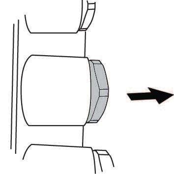
ƒ IF-Modul vor dem Steckkontakt positionieren, sodass der Stecker geführt wird (2).
ƒ IF-Modul durch gleichmäßigen seitlichen Druck auf den Platinenstecker bis zum
Anschlag aufschieben.
ƒ Vorhandene Verschraubungen Pg 9 und Pg 7 (4a) abschrauben.
ƒ Metallische EMV-Leitungseinführung(en) einschrauben (4b).
ƒ Geschirmtes Kabel abmanteln, Schirm vorbereiten und Litze abisolieren (4c).
ƒ Kabel durch Leitungseinführungen führen (4d).
ƒ Leitungseinführungen fest verschrauben (4e).
Einbau- und Betriebsanleitung Wilo-Smart IF-Modul Stratos, Wilo-Smart IF-Modul 13de Installation und elektrischer Anschluss
7.2 Installation Smart IF-Module
Fig. 2: Installation Smart IF-Module für Pumpen bis 4 kW
Fig. 3: Installation Smart IF-Modul für Pumpen von 5 bis 7,5 kW
14 WILO SE 2020-07Installation und elektrischer Anschluss de
~15 m
m
~15 m
m
Fig. 4: Anschluss Leitungsschirm für Pumpen bis 4 kW
~15 m
m
~15 m
m
Fig. 5: Anschluss Leitungsschirm für Pumpen von 5 bis 7,5 kW
ƒ Klemmenkastendeckel der Pumpe entfernen (siehe Einbau- und Betriebsanleitung
der Pumpe).
ƒ Abdeckung entfernen.
Pumpen bis 4 kW (Abb. Installation Smart IF-Module für Pumpen bis 4 kW):
ƒ IF-Modul vor dem Steckkontakt positionieren, sodass der Stecker geführt wird.
Einbau- und Betriebsanleitung Wilo-Smart IF-Modul Stratos, Wilo-Smart IF-Modul 15de Installation und elektrischer Anschluss
ƒ IF-Modul durch gleichmäßigen seitlichen Druck auf den Platinenstecker bis zum
Anschlag aufschieben.
ƒ Klemmblech montieren.
ƒ Geschirmtes Kabel abmanteln, Schirm vorbereiten und Litze abisolieren (a).
ƒ Kabel durch Leitungseinführungen führen.
ƒ Leitungseinführungen fest verschrauben.
ƒ Auflegen des Leitungsschirms mit der Schelle auf dem Klemmblech.
Pumpen ab 5 kW bis 7,5 kW (Abb. Installation Smart IF-Modul für Pumpen von 5
bis 7,5 kW):
ƒ IF-Modul vor dem Steckkontakt positionieren, sodass der Stecker geführt wird.
ƒ IF-Modul durch gleichmäßigen seitlichen Druck auf den Platinenstecker bis zum
Anschlag aufschieben.
ƒ Geschirmtes Kabel abmanteln, Schirm vorbereiten und Litze abisolieren (a).
ƒ Kabel durch Leitungseinführungen führen, sodass der Leitungsschirm in der EMV-
Leitungseinführung sicher kontaktiert wird (b).
ƒ Leitungseinführungen fest verschrauben (c).
7.3 Elektrischer Anschluss
GEFAHR
Lebensgefahr durch Stromschlag!
Der elektrische Anschluss ist von einer beim örtlichen Energieversorgungsunter-
nehmen zugelassenen Elektrofachkraft und entsprechend den geltenden örtlichen
Vorschriften [z. B. VDE-Vorschriften] auszuführen.
VORSICHT
Ein Überschreiten des maximalen Drehmoments kann das Mo-
dul beschädigen!
Das maximale Drehmoment der Klemmenschrauben beträgt 0,2 Nm. Ein Über-
schreiten kann das Modul schädigen.
1. Installation gemäß vorherigem Abschnitt durchführen.
2. Elektrische Installation der Pumpe nach Vorgaben der entsprechenden Betriebs-
anleitung durchführen.
3. Technische Daten der anzuschließenden Stromkreise auf Verträglichkeit mit den
elektrischen Daten des Smart IF-Moduls prüfen.
4. Adern entsprechend der Abbildung anschließen.
16 WILO SE 2020-07Installation und elektrischer Anschluss de
Anschluss Wilo-Smart IF-Modul Stratos:
Fig. 6: Anschluss
1. Ankommende/abgehende BUS-Leitung H/L und GND für Wilo Net auflegen.
2. Adern des digitalen Temperatursensors entsprechend der Farben (WH - weiß, RD
- rot, BK - schwarz) auflegen.
HINWEIS
Die Wilo-Stratos Doppelpumpenfunktion kann mit dem Wilo-Smart IF-Modul
Stratos nicht benutzt werden!
Anschluss Wilo-Smart IF-Modul:
Fig. 7: Anschluss
1. Ankommende/abgehende BUS-Leitung H/L und GND für Wilo Net auflegen.
Einbau- und Betriebsanleitung Wilo-Smart IF-Modul Stratos, Wilo-Smart IF-Modul 17de Inbetriebnahme/Funktionsprüfung
2. Adern des digitalen Temperatursensors entsprechend der Farben (WH - weiß, RD
- rot, BK - schwarz) auflegen.
8 Inbetriebnahme/Funktionsprüfung
HINWEIS
Es wird eine Prüfung in Verbindung mit der angeschlossenen Anlage empfohlen.
Für einige Einstellungen wird die Betriebsanleitung der Pumpe benötigt.
8.1 Einstellungen
Um Einstellungen bei Stratos-Pumpen vorzunehmen, die Einbau- und
Smart IF-Modul Stratos
Betriebsanleitung der Stratos-Baureihe lesen.
Um Einstellungen in den Menüs < 5.x.x.x > vorzunehmen, muss der DIP-
Smart IF-Modul Schalter 1 (ohne Schlüsselsymbol) unter der Klemmenkastenabdeckung
auf "ON" gestellt werden.
Tab. 6: Einstellungen
8.2 Wilo Net ID
Wilo Net ID im Pumpenmenü einstellen.
Smart IF-Modul Stratos
OFF deaktiviert die Schnittstelle.
Wilo Net ID im Pumpenmenü < 5.2.3.0 > einstellen.
Smart IF-Modul
OFF deaktiviert die Schnittstelle.
Tab. 7: Wilo Net ID
8.3 Parameter A - Bluetooth-Sperre
Der Wert 0 erlaubt ein "Pairing" mit dem Gerät, während ein Wert von 1
Smart IF-Modul Stratos das Pairing sperrt.
Um keine neuen Endgeräte zuzulassen, Wert 1 einstellen.
Der Wert 0 erlaubt ein "Pairing" mit dem Gerät, während ein Wert von 1
das Pairing sperrt.
Smart IF-Modul Um keine neuen Endgeräte zuzulassen, Wert 1 einstellen.
Parameter A wird in Menü < 5.2.4.0 > eingestellt.
Tab. 8: Parameter A - Bluetooth-Sperre
8.4 Parameter C - Bluetooth Verbindungsschlüssel löschen
Um alle Bluetooth Verbindungsschlüssel (Pairings) zu löschen, Wert 1 als Parameter
eingeben. Nach Ausführung des Befehls springt der Wert automatisch zurück auf
18 WILO SE 2020-07Wartung de
Wert 0.
Mit dem Löschen der Verbindungsschlüssel werden alle zuvor gekoppelten Geräte
wieder entkoppelt. Dadurch wird verhindert, dass zuvor gekoppelte Geräte später ge-
gebenenfalls nicht mehr berechtigten Zugriff erlangen.
Zusammen mit der Sperre A kann der Kreis der berechtigten Fernbedienungen kon-
trolliert werden.
Um alle Bluetooth Verbindungsschlüssel (Pairings) zu löschen, Wert 1 als
Parameter eingeben.
Smart IF-Modul Stratos
Nach Ausführung des Befehls springt der Wert automatisch zurück auf
Wert 0.
Um alle Bluetooth Verbindungsschlüssel (Pairings) zu löschen, Wert 1 als
Parameter eingeben.
Smart IF-Modul Nach Ausführung des Befehls springt der Wert automatisch zurück auf
Wert 0.
Parameter C wird in Menü < 5.2.5.0 > eingestellt.
Tab. 9: Parameter C - Bluetooth Verbindungsschlüssel löschen
8.5 Parameter E - Bluetooth Aktivierung
Um die Bluetooth-Funkschnittstelle zu aktivieren, Wert 1 eingeben, um
Smart IF-Modul Stratos
sie zu deaktivieren, Wert 0 eingeben.
Um die Bluetooth-Funkschnittstelle zu aktivieren, Wert 1 eingeben, um
Smart IF-Modul sie zu deaktivieren, Wert 0 eingeben.
Parameter E wird in Menü < 5.2.6.0 > eingestellt.
Tab. 10: Parameter E - Bluetooth Aktivierung
9 Wartung
Die in dieser Anleitung beschriebenen Module sind grundsätzlich wartungsfrei.
10 Störungen, Ursachen, Beseitigung
Reparaturarbeiten nur durch qualifiziertes Fachpersonal!
GEFAHR
Lebensgefahr durch Stromschlag!
Gefahren durch elektrische Energie ausschließen!
• Vor Reparaturarbeiten die Pumpe spannungsfrei schalten und gegen unbefugtes
Wiedereinschalten sichern.
• Schäden an der Netz-Anschlussleitung grundsätzlich nur durch eine qualifizierte
Elektrofachkraft beheben lassen.
Einbau- und Betriebsanleitung Wilo-Smart IF-Modul Stratos, Wilo-Smart IF-Modul 19de Ersatzteile
WARNUNG
Verbrühungsgefahr!
Bei hohen Medientemperaturen und Systemdrücken Pumpe vorher abkühlen las-
sen und System drucklos machen.
Störungen Ursache Beseitigung
Durchflusswert nicht R1 Version der Pumpe (ohne Drucksensor) Drucksensor installieren.
verfügbar.
Durchflusswert nicht Mehrstufen-Pumpe (Helix und andere) Mit diesen Pumpen nicht
verfügbar. möglich.
Durchflusswert nicht Trockenläuferpumpen einstufig (IL-E und andere) Betriebsart ändern in
verfügbar. im n-c Modus (CONST_SPEED) dp-c/dp-v.
Durchflusswert ungenau. Viskosität durch Additive beeinflusst.
Leistungs- oder Drehzahlgrenze der Pumpe ist er- Sollwert reduzieren.
reicht.
Sollwert wird nicht er-
reicht. Mehrstufen-Pumpe (Helix und andere): Maximal-
wert ist der Sensor-Meßbereichn nicht die max.
Förderhöhe der Pumpe
Tab. 11: Störungen, Ursachen, Beseitigung
Lässt sich die Betriebsstörung nicht beheben, das Fachhandwerk oder die nächstgele-
gene Wilo-Kundendienststelle oder Vertretung kontaktieren.
11 Ersatzteile
Die Ersatzteilbestellung erfolgt über örtliche Fachhandwerker und/oder den Wilo-
Kundendienst. Um Rückfragen und Fehlbestellungen zu vermeiden, bei jeder Bestel-
lung sämtliche Daten des Typenschilds von Modul und Pumpe angeben.
12 Entsorgung
12.1 Information zur Sammlung von gebrauchten Elektro- und Elektronikprodukten
Die ordnungsgemäße Entsorgung und das sachgerechte Recycling dieses Produkts
vermeiden Umweltschäden und Gefahren für die persönliche Gesundheit.
20 WILO SE 2020-07Entsorgung de
HINWEIS
Verbot der Entsorgung über den Hausmüll!
In der Europäischen Union kann dieses Symbol auf dem Produkt, der Verpackung
oder auf den Begleitpapieren erscheinen. Es bedeutet, dass die betroffenen Elek-
tro- und Elektronikprodukte nicht mit dem Hausmüll entsorgt werden dürfen.
Für eine ordnungsgemäße Behandlung, Recycling und Entsorgung der betroffenen
Altprodukte, folgende Punkte beachten:
ƒ Diese Produkte nur bei dafür vorgesehenen, zertifizierten Sammelstellen abgeben.
ƒ Örtlich geltende Vorschriften beachten!
Informationen zur ordnungsgemäßen Entsorgung bei der örtlichen Gemeinde, der
nächsten Abfallentsorgungsstelle oder bei dem Händler erfragen, bei dem das Pro-
dukt gekauft wurde. Weitere Informationen zum Recycling unter
www.wilo‑recycling.com.
Technische Änderungen vorbehalten!
Einbau- und Betriebsanleitung Wilo-Smart IF-Modul Stratos, Wilo-Smart IF-Modul 21en
Contents
1 General information................................................................................................................................... 24
1.1 About these instructions ........................................................................................................................ 24
2 Safety .......................................................................................................................................................... 24
2.1 Identification of safety instructions...................................................................................................... 24
2.2 Personnel qualifications .......................................................................................................................... 25
2.3 Danger in the event of non-observance of the safety instructions................................................. 25
2.4 Safety instructions for the operator...................................................................................................... 25
2.5 Safety instructions for inspection and installation work ................................................................... 26
2.6 Unauthorised modification and manufacture of spare parts............................................................. 26
2.7 Improper use ............................................................................................................................................. 26
3 Transport and temporary storage ............................................................................................................ 26
3.1 Scope of delivery...................................................................................................................................... 26
3.2 Transport inspection................................................................................................................................ 26
4 Intended use ............................................................................................................................................... 27
4.1 Compatibility of the firmware ................................................................................................................ 27
4.2 Pump variants ........................................................................................................................................... 28
5 Product information .................................................................................................................................. 29
5.1 Type key .................................................................................................................................................... 29
5.2 Technical data........................................................................................................................................... 29
6 Description and function........................................................................................................................... 29
6.1 Wilo Net ..................................................................................................................................................... 30
6.2 Bluetooth radio interface ........................................................................................................................ 30
6.3 Digital sensor interface ........................................................................................................................... 30
7 Installation and electrical connection...................................................................................................... 30
7.1 Stratos Smart IF module installation ..................................................................................................... 31
7.2 Smart IF module installation................................................................................................................... 32
7.3 Electrical connection ............................................................................................................................... 34
8 Commissioning / Functional test .............................................................................................................. 36
8.1 Settings...................................................................................................................................................... 36
8.2 Wilo Net ID ................................................................................................................................................ 36
8.3 Parameter A - Bluetooth block .............................................................................................................. 36
8.4 Parameter C - delete Bluetooth connection key................................................................................. 36
8.5 Parameter E - Bluetooth activation....................................................................................................... 37
22 WILO SE 2020-07en
9 Maintenance ............................................................................................................................................... 37
10 Faults, causes, remedies............................................................................................................................ 37
11 Spare parts .................................................................................................................................................. 38
12 Disposal ....................................................................................................................................................... 38
12.1 Information on the collection of used electrical and electronic products....................................... 38
Installation and operating instructions Wilo-Smart IF-Modul Stratos, Wilo-Smart IF-Modul 23en General information
1 General information
1.1 About these instructions
These installation and operating instructions are an integral part of the product. Read
these instructions before commencing work and keep them in an accessible place at
all times. Strict adherence to these instructions is a requirement for intended use and
correctly operating the product. All specifications and markings on the product must
be observed. These installation and operating instructions correspond to the relevant
version of the device and the underlying safety standards that apply at the time of
going to print.
The language of the original operating instructions is German. All other languages of
these instructions are translations of the original operating instructions.
2 Safety
These operating instructions contain basic information which must be adhered to
during installation and operation. For this reason, these installation and operating in-
structions must, without fail, be read by the installer and the responsible qualified
personnel/operator before installation and commissioning.
Not only the general safety instructions listed in the main “Safety” section must be
adhered to, but also the special safety instructions marked with danger symbols as
described below.
2.1 Identification of safety instructions
These installation and operating instructions set out safety instructions for prevent-
ing personal injury and damage to property, which are displayed in different ways:
ƒ Safety instructions relating to personal injury start with a signal word and are pre-
ceded by a corresponding symbol.
ƒ Safety instructions relating to property damage start with a signal word and are
displayed without a symbol.
Signal words
ƒ Danger!
Failure to observe safety instructions will result in serious injury or death!
ƒ Warning!
Failure to follow instructions can lead to (serious) injury!
ƒ Caution!
Failure to follow instructions can lead to property damage and possible total loss.
ƒ Notice!
Useful information on handling the product
Symbols
These instructions use the following symbols:
24 WILO SE 2020-07Safety en
General danger symbol
Danger of electric voltage
Warning – hot surfaces
Notes
2.2 Personnel qualifications
Personnel must:
ƒ Be instructed about locally applicable regulations governing accident prevention.
ƒ Have read and understood the installation and operating instructions.
Personnel must have the following qualifications.
ƒ Electrical work: Electrical work must be performed by a qualified electrician.
ƒ Installation/dismantling work: The installation/dismantling must be carried out by
a qualified technician who is trained in the use of the necessary tools and fixation
materials.
Definition of “qualified electrician”
A qualified electrician is a person with appropriate technical education, knowledge
and experience who can identify and prevent electrical hazards.
2.3 Danger in the event of non-observance of the safety instructions
Non-observance of the safety instructions can result in risk of injury to persons and
damage to product/unit. Non-observance of the safety instructions will render any
claims for damages null and void. In particular, non-observance can, for example, re-
sult in the following risks:
ƒ Danger to persons due to electrical, mechanical and bacteriological factors
ƒ Damage to the environment due to leakage of hazardous materials
ƒ Damage to property
ƒ Failure of important product/unit functions
ƒ Failure of required maintenance and repair procedures
2.4 Safety instructions for the operator
Adhere to existing accident prevention regulations! Avoid dangers caused by elec-
trical currents! Local directives and general directives [e.g. IEC, VDE, etc.] and instruc-
tions from local energy supply companies must be adhered to!
This device can be used by children from 8 years of age as well as people with reduced
physical, sensory or mental capacities or lack of experience and knowledge if they are
supervised or instructed on the safe use of the device and they understand the
Installation and operating instructions Wilo-Smart IF-Modul Stratos, Wilo-Smart IF-Modul 25en Transport and temporary storage
dangers that can occur. Children are not allowed to play with the device. Cleaning and
user maintenance must not be carried out by children without supervision.
2.5 Safety instructions for inspection and installation work
The operator must ensure that all inspection and installation work is carried out by
authorised and qualified personnel who have also sufficiently informed themselves by
studying the installation and operating instructions in detail.
Work on the product/unit may only be carried out when the system is at a standstill.
The procedure described in the installation and operating instructions for shutting
down the product/unit must be strictly observed.
Immediately on conclusion of the work, all safety and protective devices must be put
back in position and/or recommissioned.
2.6 Unauthorised modification and manufacture of spare parts
Unauthorised modification and manufacture of spare parts will impair the safety of
the product/personnel and void the manufacturer’s declarations regarding safety.
ƒ Only carry out modifications to the product following consultation with the man-
ufacturer.
ƒ Only use original spare parts and accessories authorised by the manufacturer.
The use of other parts will absolve the manufacturer of liability for any con-
sequences arising therefrom.
2.7 Improper use
The operational reliability of the supplied product is only guaranteed if used as inten-
ded and in accordance with section 4 of the installation and operating instructions.
The limit values must on no account fall below or exceed those values specified in the
catalogue/data sheet.
3 Transport and temporary storage
3.1 Scope of delivery
• Stratos Smart IF module
Stratos Smart IF module
• Installation and operating instructions
• Smart IF module
Smart IF module • Installation and operating instructions
• Metal EMC cable gland (1 x Pg 7, 1 x Pg 9)
Table 1: Scope of delivery
3.2 Transport inspection
Check delivery immediately for damage and integrity. Where necessary make a com-
plaint immediately.
26 WILO SE 2020-07Intended use en
CAUTION
Damage due to incorrect handling during transport and stor-
age!
Protect the device from moisture, frost and mechanical damage during transport
and temporary storage.
4 Intended use
ƒ Smart IF modules are designed to externally control and signal the operating
status of Wilo pumps.
ƒ Smart IF modules are not designed for safe deactivation of the pump.
DANGER
Risk of fatal electrical shock!
If used improperly, there is a risk of fatal injury due to electric shock!
• Never use the control inputs for safety functions.
• Never install the module in non-compatible devices.
4.1 Compatibility of the firmware
To ensure that all functions of the module are available, the following firmware ver-
sion must be installed on the product into which the module is installed:
Stratos Smart IF module
Pump Version Comments
Wilo-Stratos ≥ 5.09
Table 2: Stratos Smart IF module firmware version
Smart IF module
NOTICE
The firmware version (SW) can be viewed via menu < 4.4.2.0 >.
Pump Version Comments
Wilo-TOP-E Not compatible
Wilo-Stratos GIGA ≥ 1.00
Wilo-Stratos GIGA B ≥ 1.00
Installation and operating instructions Wilo-Smart IF-Modul Stratos, Wilo-Smart IF-Modul 27en Intended use
Pump Version Comments
Wilo-BL-E ≥ 1.00
Wilo-IP-E/DP-E ≥ 3.00 LCD display
Wilo-IL-E/DL-E ≥ 4.00 Matrix LCD display
Wilo-IL-E/DL-E Not compatible Segment LCD display
Wilo-Helix EXCEL ≥ 1.00
Wilo-MVIE/MVISE/MHIE/HELIX VE ≥ 3.00 LCD display
(1.1 to 4 kW)
Wilo-MVIE/MVISE/MHIE/HELIX VE ≥ 4.00 LCD display
(5.5 to 7.5 kW)
Wilo-MVIE/MVISE/MHIE/HELIX VE ≥ 1.00 LCD display
(11 to 22 kW)
Table 3: Smart IF module firmware version
NOTICE
IL-E to BF series pumps cannot be operated with IF modules.
For compatibility with products not listed above, see
www.wilo.com/automation.
4.2 Pump variants
Pumps with a deviating functional scope
The functionality may differ for Stratos GIGA, Stratos GIGA B, BL-E, IP-E/DP-E and IL-
E/DL-E series pumps.
If the menu < 5.7.2.0 > "Pressure value correction" is not available on the display, you
are dealing with a variant pump. In this case, the following functions will be unavail-
able:
ƒ Pressure value correction
ƒ Efficiency-optimised activation and deactivation in twin-head pumps
ƒ Flow rate trend display
ƒ Δp-v operating mode (VAR_DIFFPRESS)
28 WILO SE 2020-07Product information en
5 Product information
5.1 Type key
Example: Stratos Smart IF module
Smart IF module = Interface module
Stratos = Suitable for this series only
Table 4: Type key
5.2 Technical data
Technical data
General data
Terminal diameter (finely stranded without end 1.5 mm² (max.)
sleeves)
Electric circuit SELV, galvanically isolated
Mechanical mating cycles 250
Safety in accordance with EN 60335 Mains voltage up to 230 V, TN/TT system
Wilo Net interface
Cable length 200 m (max.)
Termination resistor 120 Ω (integrated, switchable)
Digital sensor interface
Interface 3.3 V digital, half-duplex
Cable length max. 3 m
Wireless interface
Interface Bluetooth® LE 4.0
Profile GATT peripheral server
Frequency band 2400.0 to 2483.5 MHz
Maximum radiated transmission power < 10 dBm (EIRP)
Table 5: Technical data
6 Description and function
Smart IF modules enhance the device with communication interfaces for various
standards.
For more information visit www.wilo.com/automation.
Installation and operating instructions Wilo-Smart IF-Modul Stratos, Wilo-Smart IF-Modul 29en Installation and electrical connection
6.1 Wilo Net
Wilo Net is a connection for gateway connectivity.
6.2 Bluetooth radio interface
Bluetooth radio interface for wireless data exchange and remote operation of the
pump using a smartphone or tablet.
6.3 Digital sensor interface
The digital sensor interface enables connection of the following sensors:
ƒ Wilo-Smart temperature sensor kit (optional accessory)
The immersion temperature sensor marked "1" records the feed temperature. The
sensor marked "2" records the return temperature.
7 Installation and electrical connection
Electrical connection may only be carried out by a qualified electrician and in accord-
ance with the applicable regulations!
DANGER
Risk of fatal electrical shock!
• Exclude risks from electrical current.
• Local directives or general directives [e.g. IEC, VDE, etc.] and instructions from
local energy supply companies must be adhered to.
DANGER
Risk of fatal electrical shock!
Before all work deactivate power supply and guard against accidental switch-on.
Work on the control module may only be started after 5 minutes have elapsed,
due to the dangerous residual contact voltage.
Check whether all connections (including potential-free contacts) are voltage-
free.
WARNING
Personal injury!
• Adhere to existing accident prevention regulations.
30 WILO SE 2020-07Installation and electrical connection en
7.1 Stratos Smart IF module installation
~15
mm
~15
mm
3 4a 4b 4c
2 4d
Mains Voltage
Attention
IF-Modul
pannung
4e
1 Mains Voltage
Attention
IF-Modul
Netzspannung Option
Achtung
L N SSM
Attention
Achtung
1 - 230V
!
Fig. 1: Smart IF module installation
ƒ Remove terminal box cover from the pump (see pump installation and operating
instructions).
ƒ Remove the cover (1).
ƒ Position the IF module in front of the plug contact so that the plug is lined up (2).
ƒ Push the IF module in as far as it will go by evenly applying pressure to the sides of
the edge connectors.
ƒ Unscrew the Pg 9 and Pg 7 (4a) screwed connections.
ƒ Screw in the metal EMC cable gland(s) (4b).
ƒ Strip the shielded cable, prepare the shield and strip the lead (4c).
ƒ Route the cable through the cable glands (4d).
ƒ Screw in the cable glands tightly (4e).
Installation and operating instructions Wilo-Smart IF-Modul Stratos, Wilo-Smart IF-Modul 31en Installation and electrical connection
7.2 Smart IF module installation
Fig. 2: Smart IF module installation for pumps up to 4 kW
Fig. 3: Smart IF module installation for pumps from 5 to 7.5 kW
32 WILO SE 2020-07Installation and electrical connection en
~15 m
m
~15 m
m
Fig. 4: Cable shield connection for pumps up to 4 kW
~15 m
m
~15 m
m
Fig. 5: Cable shield connection for pumps from 5 to 7.5 kW
ƒ Remove terminal box cover from the pump (see pump installation and operating
instructions).
ƒ Remove the cover.
Pumps up to 4 kW (Fig. Smart IF module installation for pumps up to 4 kW):
ƒ Position the IF module in front of the plug contact so that the plug is lined up.
Installation and operating instructions Wilo-Smart IF-Modul Stratos, Wilo-Smart IF-Modul 33en Installation and electrical connection
ƒ Push the IF module in as far as it will go by evenly applying pressure to the sides of
the edge connectors.
ƒ Mount the holder.
ƒ Strip the shielded cable, prepare the shield and strip the lead (a).
ƒ Route the cable through the cable glands.
ƒ Screw in the cable glands tightly.
ƒ Position the cable shield and clamp on the holder.
Pumps from 5 kW to 7.5 kW (Fig. Smart IF module installation for pumps from
5 to 7.5 kW):
ƒ Position the IF module in front of the plug contact so that the plug is lined up.
ƒ Push the IF module in as far as it will go by evenly applying pressure to the sides of
the edge connectors.
ƒ Strip the shielded cable, prepare the shield and strip the lead (a).
ƒ Route the cable through the cable glands so that the cable shield is securely in
contact in the EMC cable gland (b).
ƒ Screw in the cable glands tightly (c).
7.3 Electrical connection
DANGER
Risk of fatal electrical shock!
Electrical connection must be carried out by an electrician authorised by the local
energy supply company and in accordance with the applicable local regulations
[e.g. VDE regulations].
CAUTION
Exceeding the maximum torque may damage the module!
The maximum torque of the terminal screws is 0.2 N m. Exceeding this value may
damage the module.
1. Carry out installation as described in the previous section.
2. Carry out electrical installation of the pump as specified in the relevant installa-
tion and operating instructions.
3. Check the technical data of the electric circuits being connected to ensure they
are compatible with the electrical specifications of the Smart IF module.
4. Connect wires as illustrated.
34 WILO SE 2020-07Installation and electrical connection en
Wilo-Smart IF module Stratos connection:
Fig. 6: Connection
1. Position incoming/outgoing BUS cable H/L and GND for Wilo Net.
2. Position the wires of the digital temperature sensor according to their colours
(WH - white, RD - red, BK - black).
NOTICE
It is not possible to use the Wilo-Stratos twin-head pump function with the Wilo-
Smart IF module Stratos!
Wilo-Smart IF module connection:
Fig. 7: Connection
1. Position incoming/outgoing BUS cable H/L and GND for Wilo Net.
Installation and operating instructions Wilo-Smart IF-Modul Stratos, Wilo-Smart IF-Modul 35en Commissioning / Functional test
2. Position the wires of the digital temperature sensor according to their colours
(WH - white, RD - red, BK - black).
8 Commissioning / Functional test
NOTICE
It is recommended to test together with the connected system.
The pump's installation and operating instructions are needed for some settings.
8.1 Settings
Read the installation and operating instructions for the Stratos series to
Stratos Smart IF module
configure settings in Stratos pumps.
In order to configure settings in the < 5.x.x.x > menus, DIP switch 1 (no
Smart IF module
key symbol) under the terminal box cover must be set to "ON".
Table 6: Settings
8.2 Wilo Net ID
Adjust Wilo Net ID in pump menu .
Stratos Smart IF module
OFF deactivates the interface.
Adjust Wilo Net ID in pump menu < 5.2.3.0 >.
Smart IF module
OFF deactivates the interface.
Table 7: Wilo Net ID
8.3 Parameter A - Bluetooth block
0 enables pairing with the device, 1 blocks pairing.
Stratos Smart IF module
Set to 1 to not permit any new devices.
0 enables pairing with the device, 1 blocks pairing.
Smart IF module Set to 1 to not permit any new devices.
Parameter A is adjusted in menu < 5.2.4.0 >.
Table 8: Parameter A - Bluetooth block
8.4 Parameter C - delete Bluetooth connection key
Enter 1 as the parameter to delete all Bluetooth connection keys (pairings). After the
command has been run, the value automatically returns to 0.
Delete the connection key to delete the pairing of all previously paired devices. This
prevents previously paired devices from gaining unauthorised access at a later point.
The group of authorised remote controls can be checked along with block A.
36 WILO SE 2020-07Maintenance en
Enter 1 as the parameter to delete all Bluetooth connection keys (pair-
Stratos Smart IF module ings).
After the command has been run, the value automatically returns to 0.
Enter 1 as the parameter to delete all Bluetooth connection keys (pair-
ings).
Smart IF module
After the command has been run, the value automatically returns to 0.
Parameter C is set in menu < 5.2.5.0 >.
Table 9: Parameter C - delete Bluetooth connection key
8.5 Parameter E - Bluetooth activation
Enter 1 to activate the Bluetooth radio interface and enter 0 to deactiv-
Stratos Smart IF module
ate it.
Enter 1 to activate the Bluetooth radio interface and enter 0 to deactiv-
Smart IF module ate it.
Parameter E is set in menu < 5.2.6.0 >.
Table 10: Parameter E - Bluetooth activation
9 Maintenance
The modules described in these instructions are maintenance-free.
10 Faults, causes, remedies
Have repairs done by qualified personnel only!
DANGER
Risk of fatal electrical shock!
Ensure there are no risks arising from electrical current!
• The pump must be voltage-free and secured against unauthorised reactivation
prior to any repair work.
• Damage to the mains connecting cables should always be rectified by a qualified
electrician only.
WARNING
Risk of scalding!
At high fluid temperatures and system pressures, allow the pump to cool down
first and then depressurise the system.
Installation and operating instructions Wilo-Smart IF-Modul Stratos, Wilo-Smart IF-Modul 37en Spare parts
Faults Cause Remedy
Flow value not available. R1 version of the pump (without pressure sensor) Install pressure sensor.
Multi-stage pump (Helix, etc.) Not possible for these
Flow value not available.
pumps.
Single-stage glanded pumps (IL-E, etc.) in n-c Change operating mode
Flow value not available.
mode (CONST_SPEED) to dp-c/dp-v.
Flow value inaccurate. Viscosity influenced by additives.
Pump's performance or speed limit reached. Reduce setpoint.
Setpoint not reached. Multi-stage pump (Helix, etc.): Maximum value is
the sensor measurement range and not the maxi-
mum pump delivery head
Table 11: Faults, causes and remedies
If the malfunction cannot be rectified, consult a specialist technician or the nearest
Wilo customer service or representative location.
11 Spare parts
Spare parts may be ordered via a local installer and/or Wilo customer service. To avoid
queries and order errors, please supply all data on the rating plate of the module and
pump with every order.
12 Disposal
12.1 Information on the collection of used electrical and electronic products
Proper disposal and appropriate recycling of this product prevents damage to the en-
vironment and putting your personal health at risk.
NOTICE
Disposal in domestic waste is prohibited!
In the European Union this symbol may be included on the product, the packaging
or the accompanying documentation. It means that the electrical and electronic
products in question must not be disposed of along with domestic waste.
Please note the following points to ensure proper handling, recycling and disposal of
the used products in question:
ƒ Hand over these products at designated, certified collection points only.
ƒ Observe the locally applicable regulations!
38 WILO SE 2020-07Sie können auch lesen