Bedienungsanleitung Adjustment instructions Instrucciones Notice d'utilisation Istruzioni - Rechner Sensors
←
→
Transkription von Seiteninhalten
Wenn Ihr Browser die Seite nicht korrekt rendert, bitte, lesen Sie den Inhalt der Seite unten
Bedienungsanleitung · Adjustment instructions
Instrucciones · Notice d‘utilisation · Istruzioni
Vorwort • Introduction • Introducción • Préface • Introduzione

    Wichtige Hinweise

    Diese Bedienungsanleitung vor der Inbetriebnahme lesen und genau beachten. Die Geräte dürfen nur
    von Personen benutzt, gewartet und instand gesetzt werden, die mit der Bedienungsanleitung und den
    geltenden Vorschriften über Arbeitssicherheit und Unfallverhütung vertraut sind. Entfernen der Seri-
    ennummer sowie Veränderungen am Gerät oder unsachgemäßer Gebrauch führen zum Verlust des
    Garantieanspruches. Die Bedienungsanleitung ist aufzubewahren.

    Important Note:

    Please read carefully and pay full attention to this instruction manual before powering up this device for
    the first time. The use, servicing and initial operation of this device is only permitted for persons who are
    familiar with the instruction manual and the current rules of safety in the work place and accident-pre-
    vention. Removal of the serial number, changes to the units or improper use will lead to loss of guaran-
    tee. The instruction manual must be kept.

    Nota importante:

    Estas instrucciones de servicio deben leerse y respetarse escrupulosamente antes de la puesta en mar-
    cha. Sólo las personas que conozcan perfectamente las instrucciones de servicio y las normas en vigor
    sobre seguridad en el trabajo y prevención de accidentes pueden manejar, mantener y poner en mar-
    cha los aparatos. La eliminación del número de serie y las modificaciones realizadas en el aparato o
    el uso indebido del mismo provocan la pérdida de la garantía. Las instrucciones de operación deben
    conservarse para futuras consultas.

    Remarques importantes:

    La présente notice est à lire attentivement avant mise en service du matériel. Sa stricte observation est
    impérative. Les appareils peuvent être utilisés, entretenus ou réparés uniquement par du personnel
    disposant du manuel d’utilisation et des attributions nécessaires en ce qui concerne la sécurité du travail
    et la prévention des accidents. La suppression du numéro de série, la modification de l’appareil ou son
    utilisation inappropriée conduiront à la perte de la garantie. Cette notice d’utilisation est à conserver pour
    de futures consultations.

    Nota importante:

    Vi invitiamo a seguire attentamente queste istruzioni prima di collegare il sensore. Queste apparecchia-
    ture devono essere usate e messe in funzione da persone competenti, che conoscono le istruzioni, le
    norme vigenti di sicurezza e le norme di prevenzione incidenti. Il distacco del numero di serie e modifi-
    che all’apparecchiatura o l’utilizzo improprio comportano il non riconoscimento della garanzia. Si prega
    di conservare il manuale di istruzioni per future consultazioni.

    © RECHNER 04.2019 - Printed in Germany
    Irrtümer und Änderungen ohne vorherige Ankündigung vorbehalten.
    All specifications are subject to change without notice.
    Se reserva el derecho a efectuar errores y modificaciones sin previo aviso.
    Sous réserve d’erreurs et modifications sans préavis.
    Tutti i dati sono soggetti a variazione senza preavviso.

2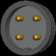
Inhaltsverzeichnis • Table of contents • Indice • Table des matières • Indice

DEUTSCH Wichtige Hinweise                                                       Seite          2
            Inhaltsverzeichnis                                                  Seite          3
            Erste Schritte                                                      Seite          6
            Allgemeine Beschreibung                                             Seite          7
            Montage                                                             Seite          8
            Elektrischer Anschluss                                              Seite     9 - 10
            Verlegung der Leitungen                                             Seite         10
            EasyTeach-Philosophie                                               Seite         11
            Einstellungen ETW                                                   Seite         12
            Einstellungen ETB                                                   Seite         13
            Einstellungen ETM                                                   Seite         14
            IO-Link                                                             Seite         15
            Wartung, Instandsetzung, Entsorgung                                 Seite         15

ENGLISH     Important notes                                                     Page           2
            Table of contents                                                   Page           3
            First steps                                                         Page          18
            General description                                                 Page          19
            Mounting                                                            Page          20
            Electrical connection                                               Page     21 - 22
            Installation of cables                                              Page          22
            EasyTeach-philosophy                                                Page          23
            Adjustment ETW                                                      Page          24
            Adjustment ETB                                                      Page          25
            Adjustment ETM                                                      Page          26
            IO-Link                                                             Page          27
            Maintenance, repair, disposal                                       Page          27

ESPAÑOL Nota
        Índice
              importante:                                                       Página
                                                                                Página
                                                                                               2
                                                                                               3
            Primeros pasos                                                      Página        30
            Descripción general                                                 Página        31
            Montaje                                                             Página        32
            Conexión eléctrico                                                  Página   33 - 34
            Colocación del cable                                                Página        34
            Filosofía EasyTeach                                                 Página        35
            Ajuste ETW                                                          Página        36
            Ajuste ETB                                                          Página        37
            Ajuste ETM                                                          Página        38
            IO-Link                                                             Página        39
            Mantenimiento, Reparación, Eliminación de desechos                  Página        39

            Remarques importantes:                                              Page           2
FRANÇAIS Table des matières                                                     Page           3
            Premières étapes                                                    Page          42
            Description générale                                                Page          43
            Montage                                                             Page          44
            Raccordement électrique                                             Page     45 - 46
            Installation des câbles                                             Page          46
            Philosophie d’auto-apprentissage EasyTeach                          Page          47
            Auto-apprentissage ETW                                              Page          48
            Auto-apprentissage ETB                                              Page          49
            Auto-apprentissage ETM                                              Page          50
            IO-Link                                                             Page          51
            Maintenance, Réparation, Mise au rebut                              Page          51

            Nota importante                                                     Pagina         2
ITALIANO    Indice                                                              Pagina         3
            Primi passi                                                         Pagina        54
            Descrizione generale                                                Pagina        55
            Montaggio                                                           Pagina        56
            Collegamento elettrico                                              Pagina   57 - 58
            Posa dei cavi                                                       Pagina        58
            Filosofia EasyTeach                                                 Pagina        59
            Impostazione ETW                                                    Pagina        60
            Impostazione ETB                                                    Pagina        61
            Impostazione ETM                                                    Pagina        62
            IO-Link                                                             Pagina        63
            Manutenzione, Riparazione, Smaltimento                              Pagina        63

                                                                                               3
4
Inhaltsverzeichnis

Wichtige Hinweise                     Seite.....................2

Inhaltsverzeichnis                    Seite.....................3

Erste Schritte                        Seite.....................6

Allgemeine Beschreibung               Seite.....................7

Montage                               Seite.....................8

Elektrischer Anschluss                Seite..............9 - 10

Verlegung der Leitungen               Seite...................10

EasyTeach-Philosophie                 Seite................... 11

Einstellung ETW                       Seite...................12

Einstellung ETB                       Seite...................13

Einstellung ETM                       Seite...................14

IO-Link                               Seite...................15

Wartung, Instandsetzung, Entsorgung   Seite...................15

                                                                    5
Erste Schritte
Vielen Dank,
dass Sie sich für ein Gerät von RECHNER Sensors entschieden haben. Seit über 50 Jahren hat sich
RECHNER Sensors mit Engagement, Produktinnovationen und bester Qualität eine weltweite Spitzen-
position am Markt erarbeitet.
Symbolerklärungen
i Information: Zusätzlicher Hinweis
Achtung: Wichtige Information / Sicherheitshinweis
Handlungsbedarf: Hier ist eine Einstellung oder eine Handlung vorzunehmen
Vor der Installation
• Packen Sie das Gerät aus und überprüfen Sie Ihre Lieferung auf Beschädigungen, Richtigkeit
und Vollständigkeit.
• Falls Beschädigungen vorliegen, informieren Sie bitte Ihren Lieferanten und den verant-
wortlichen Zustelldienst.
• Bei offenen Fragen oder Problemen stehen wir Ihnen gerne für weitere Hilfe und Lösungen
zur Verfügung.
6Allgemeine Beschreibung
Die kapazitiven Sensoren, unsere Kurzbezeichnung KAS, generieren ein kapazitives Feld im Bereich
der aktiven Fläche. Jedes Produkt, das heißt Flüssigkeit, Pasten, Schüttgut und Festkörper mit eine Die-
lektrizitätskonstante er > 1,1 wird erfasst und als Schaltsignal ausgegeben, so dass über das verbundene
Kontrollsystem das Niveau bzw. die gewünschte Abtastaufgabe durchgeführt werden kann.
Mit den kapazitiven Sensoren können Elektronik-Schaltungen, SPS, ebenso Relais oder Schütze direkt
angesteuert werden.
KAS sind einsetzbar in Maschinen, Anlagen und Fahrzeugen
• Zur Füllstandsüberwachung von Flüssigkeiten, pastösen Stoffen oder Schüttgütern, auch
durch nichtmetallische Trennwände hindurch, wenn die Dielektrizitätskonstante des zu
erfassenden Mediums (ca. Faktor 5) größer ist.
• Als Endschalter, berührungslose Grenztaster, zur Überwachung und Positionierung, als
Impulsgeber für Zählaufgaben, Weg- und Drehzahlmessung und vieles mehr.
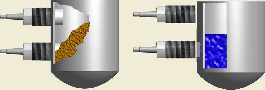
Erkennung aller Materialien di- Erkennung aller Materialien
rekt im Behälter (Nichtbündig durch einen nicht metallischen
einbaubar) Behälter oder ein Sichtfenster
(bündig einbaubar)
7Montage
Bündiger oder Nichtbündiger Einbau
Es sind zwei Einbauarten bei den kapazitiven Sensoren zu unterscheiden:
Für bündigen Einbau in Metall und andere Materialien. Diese können auch dicht an dicht
angeordnet werden (siehe Abb. 1 und 3) und sind besonders geeignet zur berührungslosen
Abtastung von Festkörpern oder durch Nichtmetall-Trennwände oder durch einen Bypass
(max. Wandstärke 4 mm).
Für nichtbündigen Einbau in Metall und andere Materialien. Bei Montage von zwei oder
mehreren Sensoren nebeneinander muss ein Zwischenraum / Freiraum vorgesehen werden
(siehe Abbildung 2 und 4). Diese eignen sich besonders für Anwendungen, bei denen das
abzutastende Medium mit dem Tastkopf in Berührung kommt (z.B. Füllstandsüberwachung
von Schüttgut, Paste oder Flüssigkeit).
“Gewindefreie Abb.2
Zone“ Freizone ≥ 3 x d KAS-...-26/...-...-G1-...
Abb.1 dämpfendes Durchmesser “d“ min. 25 mm*
Material
bündig montiert nichtbündig montiert
KAS-...-26/...-...-G1/2-...
min. 15 mm*
a
b
Abb.3 Abb.4
Zwei gegenüberliegende Sensoren müssen mindestens mit dem 2,2-fachen Schaltabstand
voneinander entfernt angebracht werden (Abstand “a“).
i Bei nichtbündig einbaubaren Sensoren muss die gewinderfreie Zone mindestens mit dem
1,5-fachen Schaltabstand von dem dämpfenden Material entfernt angebracht werden (Ab-
stand “b“).
*Wird dieses Maß unterschritten, verringert sich die Empfindlichkeit
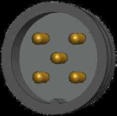
8Pinbelegung
Pinbelegung für Sensoren mit Steckervariante (Draufsicht)
4 3 4 3
5
i Pin 5 ist nur bei Sensoren mit
ETW-Funktion vorhanden.
1 2 1 2
Elektrischer Anschluss
Dreidraht-Näherungsschalter mit Binärausgang können in Reihen- oder Parallelschaltung
ähnlich wie mechanische Kontakte betrieben werden. Zu beachten ist der gerätetypische
Spannungsfall, die Restspannung Ud, die sich bei Reihenschaltung entsprechend der Gerä-
teanzahl multipliziert. Bei Parallelschaltung von Sensoren mit FET-Ausgang übernimmt der
zuerst geschaltete Ausgang den Gesamtlaststrom.
Reihenschaltung Parallelschaltung
3-Draht DC NPN
3-Draht DC PNP
9Elektrischer Anschluss
Elektrischer Anschluss EasyTeach by Wire (ETW)
NPN Schließer NPN Öffner NPN Antivalent
ETW +Teach ETW +Teach ETW +Teach
- Betrieb - Betrieb - Betrieb
PNP Schließer PNP Öffner PNP Antivalent
ETW +Teach ETW +Teach ETW +Teach
- Betrieb - Betrieb - Betrieb
Bei allen Ausführungen mit EasyTeach-Funktion, gibt es zwei Modi:
Verbindet man den Teacheingang mit UB+, ist der Teach-Modus aktiviert.
Verbindet man den Teacheingang mit GND, ist das Gerät im Betriebsmodus.
Elektrischer Anschluss EasyTeach by Button (ETB) / Magnet(ETM)
NPN Schließer NPN Öffner NPN Antivalent
PNP Schließer PNP Öffner PNP Antivalent
Achtung:
Bei induktiver Last ist eine entsprechende Schutzbeschaltung (z.B. Freilaufdiode) vorzusehen.
Verlegung der Leitungen
Steuerleitungen für die Auswerter sollten getrennt oder abgeschirmt von Hauptstromleitungen ver-
legt werden, weil induktive Spannungsspitzen im Extremfall die Auswerteelektronik trotz eingebauter
Schutzbeschaltung zerstören können. Speziell bei längeren Leitungsstrecken > 5 m sind abgeschirmte
Kabel oder verdrillte Leitungen zu empfehlen.
Geräte mit hoher Nahfeldstärke, z. B. Sprechfunkgeräte mit großer Leistung oder Störquellen im un-
teren Frequenzbereich, z. B. Lang-, Mittel-, Kurzwellensender nicht unmittelbar in der Nähe von Sonden
und Auswertern betreiben oder zusätzliche Maßnahmen zur Eliminierung von Fehlsignalen durchführen.
10EasyTeach-Philosophie
Einstellung ETW:
Leereinstellung Durch das Aktivieren der Teach-Verbindung (Teach-Litze
/ Teach-Pin und Betriebsspannung UB+) wird das Easy-
Teach-Menü gestartet. Das Menü durchläuft nacheinander die
verschiedenen Einstellungen. Der gewünschte Menüpunkt ist
durch das Trennen dieser Verbindung ausgewählt.
Volleinstellung
Einstellung ETB:
Durch das Drücken der EasyTeach-Taste aktiviert man das
EasyTeach-Menü. Das Menü durchläuft nacheinander die ver-
Werkseinstellung* schiedenen Einstellungen. Das Menü durchläuft nacheinander
die verschiedenen Einstellungen. Der gewünschte Menüpunkt
wird über das Loslassen des Tasters ausgewählt.
Einstellung ETM:
Test Durch das Vorhalten des EasyTeach-Magnets an dem Teach-
spot aktiviert man das EasyTeach-Menü. Der gewünschte
Menüpunkt wird über das wegnehmen des Magnets ausgewählt.
LED LED
Ausgangsversion Anschluss EasyTeach-Verbindung Grün - Klassik Gelb - Klassik
Gelb - NormLine Gelb - NormLine
Antivalent Kabel Graue Litze Ausgang A1 Ausgang A2
Antivalent Stecker Pin 5 Ausgang A1 Ausgang A2
Schließer oder Öffner Kabel Weiße Litze Ausgang A1 Ausgang A1
Schließer Stecker Pin 4 Ausgang A1 Ausgang A1
Öffner Stecker Pin 2 Ausgang A1 Ausgang A1
EasyTeach-Charts
Die EasyTach-Charts dienen zur optischen Menüführung. Sie verdeutlichen das Blinkverhalten der LED
und das Takten des Ausgangs bei den verschiedenen Menüpunkten.
Serie High Performance (KAS-...-HP) Serie NormLine (KAS-...-NL)
Antivalent
Leereinstellung Leerabgleic
Leereinstellung Initialisierung Leerabgleich Initialisi
Volleinstellung Vollabgleic
Volleinstellung Initialisierung V
Werkseinstellung Nicht vorhanden V
Test Te
Serie High Performance (KAS-....-HP) Schließer oder Öffner
Leereinstellung
Leereinstellung Initialisierung
Volleinstellung
Volleinstellung Initialisierung
Test
*Falls vorhanden 11Einstellungen ETW
Achtung:
Während der Einstellung den Abstand zum detektierten Objekt bzw. den Füllstand nicht
verändern!
Die EasyTeach-Einstellung bietet die Möglichkeit der Voll- und Leereinstellung. Wir empfehlen, die Ein-
stellung immer mit dem abzutastenden Produkt durchzuführen, also die VOLLEINSTELLUNG.
Die Volleinstellung ist unabhängig von der Leereinstellung. Wenn die Einstellung mit dem abzutastenden
Produkt nicht möglich ist, kann eine Leereinstellung durchgeführt werden, z. B. wenn das Produkt bei der
Aktivierung des Sensors noch nicht bekannt ist, aber sicher gestellt sein muss, dass keine Überfüllung
stattfindet. Wir empfehlen, nach der ersten Befüllung die Volleinstellung durchzuführen, um den Sensor
optimal auf das abzutastende Material einzustellen.
Leereinstellung - aktive Fläche frei
• Aktive Fläche des Sensors ist frei.
• EasyTeach-Verbindung aktivieren und aktiv halten bis die LED blinkt (siehe EasyTeach-Chart). Ausgang
pulst dementsprechend.
• Teach-Verbindung trennen
• Die LED blinkt während des Initialisierungsvorgangs mit höherer Frequenz. Ausgang pulst dementsprechend.
Die Leereinstellung ist durchgeführt, wenn die LED statisch leuchtet. Der Sensor ist, bezogen auf
die Einbausituation, auf den größten zulässigen Schaltabstand eingestellt. Die Schalthysterese wird
automatisch errechnet.
VOLLEINSTELLUNG - aktive Fläche bedeckt
• Die Sensorfläche muss mit dem abzutastenden Produkt komplett bedeckt, bzw. das Produkt muss
im gewünschten Schaltabstand positioniert sein.
• EasyTeach-Verbindung aktivieren und aktiv halten bis die LED blinkt (siehe EasyTeach-Chart). Ausgang
pulst dementsprechend.
• Teach-Verbindung trennen.
• Die LED blinkt während des Initialisierungsvorgangs mit höherer Frequenz. Ausgang pulst dementsprechend.
Die Volleinstellung ist durchgeführt, wenn die LED statisch leuchtet. Der Sensor ist auf die zur Pro-
dukterkennung richtige Empfindlichkeit eingestellt. Die Schalthysterese wird automatisch errechnet.
Werkseinstellung
• EasyTeach-Verbindung aktivieren und aktiv halten bis die LED im Wechsel grün und gelb blinkt.
Ausgang pulst dementsprechend.
• Teach-Verbindung trennen
Der Auswerter ist wieder im Auslieferungszustand.
Testfunktion
Die Testfunktion dient zur Überprüfung ob der Sensor richtig angeschlossen ist.
• EasyTeach-Verbindung aktivieren aktiv halten bis die LED blinkt (siehe EasyTeach-Chart). Ausgang
pulst dementsprechend.
Die Testfunktion ist so lange aktiv bis die Teach-Verbindung getrennt wird. Die eingestellten Werte
bleiben unverändert.
Nach dem Beenden der Einstellung legen Sie die EasyTeach-Litze auf GND (-). So vermeiden
i Sie versehentliche Einstellungen am Gerät.
12Einstellungen ETB
Achtung:
Während der Einstellung den Abstand zum detektierten Objekt bzw. den Füllstand nicht
verändern!
Die EasyTeach-Einstellung bietet die Möglichkeit der Voll- und Leereinstellung. Wir empfehlen, die Ein-
stellung immer mit dem abzutastenden Produkt durchzuführen, also die VOLLEINSTELLUNG.
Die Volleinstellung ist unabhängig von der Leereinstellung. Wenn die Einstellung mit dem abzutastenden
Produkt nicht möglich ist, kann eine Leereinstellung durchgeführt werden, z. B. wenn das Produkt bei der
Aktivierung des Sensors noch nicht bekannt ist, aber sicher gestellt sein muss, dass keine Überfüllung
stattfindet. Wir empfehlen, nach der ersten Befüllung die Volleinstellung durchzuführen, um den Sensor
optimal auf das abzutastende Material einzustellen.
Leereinstellung - aktive Fläche frei
• Aktive Fläche des Sensors ist frei.
• Die Teach-Taste gedrückt halten bis die LED blinkt (siehe EasyTeach-Chart).
• Teach-Taste loslassen.
• Die LED blinkt während des Initialisierungsvorgangs mit höherer Frequenz.
Die Leereinstellung ist durchgeführt, wenn die LED statisch leuchtet. Der Sensor ist, bezogen auf
die Einbausituation, auf den größten zulässigen Schaltabstand eingestellt. Die Schalthysterese wird
automatisch errechnet.
VOLLEINSTELLUNG - aktive Fläche bedeckt
• Die Sensorfläche ist mit dem abzutastenden Produkt komplett bedeckt, bzw. das Produkt ist im
gewünschten Schaltabstand positioniert sein.
• Die Teach-Taste gedrückt halten bis die LED blinkt (siehe EasyTeach-Chart).
• Teach-Taste loslassen.
• Die LED blinkt während des Initialisierungsvorgangs mit höherer Frequenz.
Die Volleinstellung ist durchgeführt, wenn die LED statisch leuchtet. Der Sensor ist auf die zur Pro-
dukterkennung richtige Empfindlichkeit eingestellt. Die Schalthysterese wird automatisch errechnet.
Werkseinstellung
• Die Teach-Taste gedrückt halten bis die LED im Wechsel grün und gelb blinkt.
• Teach-Taste loslassen.
Der Auswerter ist wieder im Auslieferungszustand.
Testfunktion
Die Testfunktion dient zur Überprüfung ob der Sensor richtig angeschlossen ist.
• Die Teach-Taste gedrückt halten bis die LED blinkt (siehe EasyTeach-Chart).
Die Testfunktion ist so lange aktiv bis die Teach-Taste losgelassen wird. Die eingestellten Werte
bleiben unverändert.
13Einstellungen ETM
Achtung:
Während der Einstellung den Abstand zum detektierten Objekt bzw. den Füllstand nicht
verändern!
Die EasyTeach-Einstellung bietet die Möglichkeit der Voll- und Leereinstellung. Wir empfehlen, die Ein-
stellung immer mit dem abzutastenden Produkt durchzuführen, also die VOLLEINSTELLUNG.
Die Volleinstellung ist unabhängig von der Leereinstellung. Wenn die Einstellung mit dem abzutastenden
Produkt nicht möglich ist, kann eine Leereinstellung durchgeführt werden, z. B. wenn das Produkt bei der
Aktivierung des Sensors noch nicht bekannt ist, aber sicher gestellt sein muss, dass keine Überfüllung
stattfindet. Wir empfehlen, nach der ersten Befüllung die Volleinstellung durchzuführen, um den Sensor
optimal auf das abzutastende Material einzustellen.
Leereinstellung - aktive Fläche frei
• Aktive Fläche des Sensors ist frei.
• Den Teach-Magnet an den Teachspot halten bis die LED blinkt (siehe EasyTeach-Chart).
• Teach-Magnet entfernen
• Die LED blinkt während des Initialisierungsvorgangs mit höherer Frequenz.
Die Leereinstellung ist durchgeführt, wenn die LED statisch leuchtet. Der Sensor ist, bezogen auf
die Einbausituation, auf den größten zulässigen Schaltabstand eingestellt. Die Schalthysterese wird
automatisch errechnet.
VOLLEINSTELLUNG - aktive Fläche bedeckt
• Die Sensorfläche ist mit dem abzutastenden Produkt komplett bedeckt, bzw. das Produkt ist im
gewünschten Schaltabstand positioniert sein.
• Den Teach-Magnet an den Teachspot halten bis die LED blinkt (siehe EasyTeach-Chart).
• Teach-Magnet entfernen
• Die LED blinkt während des Initialisierungsvorgangs mit höherer Frequenz.
Die Volleinstellung ist durchgeführt, wenn die LED statisch leuchtet. Der Sensor ist auf die zur Pro-
dukterkennung richtige Empfindlichkeit eingestellt. Die Schalthysterese wird automatisch errechnet.
Werkseinstellung
• Den Teach-Magnet an den Teachspot halten bis die LED im Wechsel grün und gelb blinkt.
• Teach-Magnet entfernen
Der Auswerter ist wieder im Auslieferungszustand.
Testfunktion
Die Testfunktion dient zur Überprüfung ob der Sensor richtig angeschlossen ist.
• Den Teach-Magnet an den Teachspot halten bis die LED blinkt (siehe EasyTeach-Chart).
Die Testfunktion ist so lange aktiv bis der Teach-Magnet entfernt wird. Die eingestellten Werte bleiben
unverändert.
14IO-Link
Ist der Sensor mit einer IO-Link-Schnittstelle ausgestattet, können Sie mit dieser Schnittstelle verschiedene
Sensorwerte und Parameter auslesen und einstellen. Um den Sensor im IO-Link Modus zu betreiben,
benötigen sie eine IO-Link-fähige Baugruppe (IO-Link Master). Während der IO-Link Kommunikation ist
die Einstellung über EasyTeach nicht möglich.
Weiter Informationen zum Thema IO-Link und die zur Einrichtung des IO-Link Sensors notwendigen
IODDS finden Sie unter:
https://www.rechner-sensors.com/dokumentation/io-link
Wartung, Instandsetzung, Entsorgung
• Eine Wartung der Geräte ist bei bestimmungsgemäßen Gebrauch nicht erforderlich.
• Das Reparieren und Instandsetzen unserer Geräte ist nicht möglich. Bei Fragen wenden Sie sich
bitte direkt an unseren Service.
• Bitte Entsorgen Sie Geräte umweltgerecht gemäß den gültigen nationalen Bestimmungen.
1516
Table of content

Table of content                Page.....................2

Important Note                  Page.....................3

First steps                     Page...................18

General description             Page...................19

Mounting                        Page...................20

Electrical connection           Page............21 - 22

Installation of cables          Page...................22

EasyTeach-philosophy            Page...................23

Adjustment ETW                  Page...................24

Adjustment ETB                  Page...................25

Adjustment ETM                  Page...................26

IO-Link                         Page...................27

Maintenance, repair, disposal   Page...................27

                                                             17
First steps
Thank you,
for choosing a device from RECHNER Sensors. For 50 years RECHNER Sensors has established a
leadership position with commitment, product innovation and quality.
Symbols
i Information: Additional note
Caution: Important note / safety note
Need for action: An action or an adjustment is necessary
Before installing
• Unpack the device / unit and check your delivery is complete, correct, and that there is no
damage.
• If there is any damage, please inform your supplier and those responsible for delivery
• For further questions or problems we are at your disposal to support or find solutions
18General description
The capacitive sensors, our abbreviation KAS, generate a capacitive field within the area of the active
surface. All media, liquid, pastes, bulk material or solids, with a dielectric constant er > 1,1 will be detected
and indicated as a switching signal, so that the level or the desired detection task can be controlled via
the connected PLC or control system.
Electronic circuits, PLCs, relays or contactors can be activated directly by capacitive sensors.
KAS can be used in machines, systems and vehicles for:
• Level monitoring of liquids, pastes or bulk material, and also through non-metal windows,
if the dielectric constant of the material to be detected is higher (approx. Factor 5).
• As limit switches, contact-less position switches for monitoring and positioning, as pulse
generator for counting tasks, distance and speed measurements and for many other
applications.
Detection of all materials di- Detection of all materials
rectly in a container (non-flush through a non-metallic con-
mountable) tainer or an inspection window
(flush mountable)
19Mounting
Flush mounting or non-flush mounting
There are two different types of capacitive sensors:
For flush mounting in metal or other materials. These sensors can be mounted close
together (see Fig. 1 and 3) and are specially designed for contact-less detection of solids or
liquids through non-metal containers (max. wall-thickness 4 mm)
For non-flush mounting in metal or other materials. When mounting two or more sensors
side by side a space / free zone must be provided (see Fig. 2 and 4). These sensors are de-
signed for applications where the detecting material comes into contact with the active area
of the sensor (e.g. level monitoring of bulk materials or liquid
Damping Fig.2
material Free zone ≥ 3 x d KAS-...-26/...-...-G1-...
Fig.1 Damping Diameter “d“ min. 25 mm*
material
Flush mountable Non-flush mountable
KAS-...-26/...-...-G1/2-...
min. 15 mm*
a
b
Fig.3 Fig.4
Two opposite sensors have to be mounted with a distance of at least 2,2 times of the oper-
ating distance (distance “a”).
i For non flush mountable sensors, the zone without a thread has to be mounted with a dis-
tance of at least 1,5 times of the operating distance from the damping material (distance “b”)
*If this dimension is reduced, the sensitivity is reduced.
20Pin connection
Pin connection for pluggable sensors (top view)
4 3 4 3
i
Pin 5 is only available for
sensors with ETW-function
5
1 2 1 2
Electrical connection
3-wire sensors with binary output can be used in series or parallel connection, similar to mechanical con-
tacts. The type-typical voltage drop and the residual voltage Ud , which must be multiplied in accordance
with the number of sensors for series connection, must be noted. In the case of parallel connection of
sensors with FET-output, the first switched output takes over the total load current.
Series connection Parallel connection
3-Wire DC NPN
3-Wire DC PNP
21Electrical connection
Electrical connection EasyTeach by Wire (ETW)
NPN Normally open NPN Normally closed NPN Antivalent
ETW +Teach ETW +Teach ETW +Teach
- Operating - Operating - Operating
PNP Normally open PNP Normally closed PNP Antivalent
ETW +Teach ETW +Teach ETW +Teach
- Operating - Operating - Operating
EasyTeach versions have two modes:
By connecting the Teach input with UB+, the Teach mode is activated
By connecting the Teach input with GND, the Operating mode is activated
Electrical connection EasyTeach by Button (ETB) / Magnet (ETM)
NPN Normally open NPN Normally closed NPN Antivalent
PNP Normally open PNP Normally closed PNP Antivalent
Attention:
For inductive loads, a corresponding protective circuit (e.g. freewheeling diode) must be provided.
Installation of cables
Wiring of the sensor should be routed separately or screened from heavy conductor lines, as in ex-
treme cases inductive peak voltages can destroy the sensors despite the integrated protective circuit.
Screened cable or twisted lines are recommended, especially for longer cable runs > 5 m. Direct control
of electric light bulbs is to be avoided, because during the switch-on moment cold current is many times
the rated current and can destroy the output stage of the sensor.
Units with strong fields nearby, e. g. high power walkie-talkies, or noise sources in the lower frequen-
cy range, e. g. long, middle or short wave transmitters should not be operated close to the sensors or
additional measures have to be taken in order to eliminate incorrect operation.
22EasyTeach-philosophy
Adjustment ETW:
Adjustment „empty“ The EasyTeach menu starts, by activating the EasyTeach con-
nection (Teach wire / Teach pin with the supply voltage UB+).
The menu goes through the different settings. The desired
Menu point is selected when breaking the connection
Adjustment „full“
Adjustment ETB:
Pushing the EasyTeach-Button activates the EasyTeach menu.
The menu goes through the different settings. The desired menu
Factory reset* item is selected by releasing the EasyTeach-Button
Adjustment ETM:
Holding the EasyTeach magnet on the teachspot activates the
Test EasyTeach menu. The menu goes through the different settings.
The desired menu item is selected by removing the magnet
LED LED
Output Connection EasyTeach-Connection Green - Classic Yellow - Classic
Yellow - NormLine Yellow - NormLine
Antivalent Cable Grey wire Output A1 Output A2
Antivalent Connector Pin 5 Output A1 Output A2
N.O. or N.C. Cable White wire Output A1 Output A1
N.O Connector Pin4 Output A1 Output A1
N.C Connector Pin2 Output A1 Output A1
EasyTeach-Chart
The EasyTeach charts are used for optical menu navigation. They illustrate the flashing behaviour of the
LED and the switching of the output at the various menu items
Classic sensor - antivalent Serie NormLine
Adjustment „empty“ Leerabgleic
Initializing „empty“ Leerabgleich Initialis
Adjustment „full“ Vollabgleic
Initializing „full“ V
Factory reset Not available V
Test Te
Classic sensor - normally open or normally closed
Adjustment “empty“
Initializing “empty“
Adjustment “full“
Initializing “full“
Test
*If existing 23Adjustment ETW
Attention:
Do not change the distance to the detecting object or the filling level during the adjustment
The EasyTeach-Adjustment provides the possibility for full or empty adjustment. We recommend, always
to do the FULL ADjUSTMENT. Ensure that the active area of the sensor is in contact with the
product to be detected or the product is placed in the active area of the sensor. The full adjustment does
not require an empty adjustment beforehand. When the adjustment with the product to be detected is not
possible, an empty adjustment can be made, e. g. the product to be detected is not known at the time of
the sensor adjustment, but an overfilling must be excluded. When the level is filled for the first time, we
recommend making a full adjustment so that the sensor is optimally adjusted on the material to be detected.
Empty adjustment - Active surface free
• The active surface of the sensor is free.
• Activate the EasyTeach menu and keep it active until the LED flashes. The output pulses accordingly
(see EasyTeach-Chart).
• Break the connection.
• During the initialization process the LED is flashing with higher frequency. The output pulses accordingly.
The empty adjustment is finished when the LED is static. With this adjustment the sensor has the
largest sensing distance that is possible at the current mounting position. The switching hysteresis is
calculated automatically.
FULL ADjUSTMENT - Active surface covered
• The active surface of the sensor must be covered completely with the product to be detected or the
product must be in the desired position.
• Activate the EasyTeach menu and keep it active until the LED flashes. The output pulses accordingly.
(see EasyTeach-Chart)
• Break the connection.
• During the initialization process the LED is flashing with higher frequency. The output pulses accordingly.
The full adjustment is finished when the LED is static. The sensor is now optimally adjusted for the
detection of the product currently being used and the current mounting conditions. The switching
hysteresis is calculated automatically.
Factory reset
For the factory reset, please do the following steps:
• Activate the EasyTeach menu and keep it active until the LED flashes green and yellow alternately.
• Break the connection.
The sensor is back in delivery condition.
Test function
The test function can be used to check that the sensor is connected correctly.
• Activate the EasyTeach menu and keep it active until the LED flashes. The output pulses accordingly.
(see EasyTeach-Chart)
The test function is activated until you disconnect the EasyTeach-Wire. The adjusted values stay
unchanged.
After making the adjustment put the EasyTeach-Wire on GND of the supply voltage (UB-).
24 i This prevents unintentional adjustments on the device.Adjustment ETB
Attention:
Do not change the distance to the detecting object or the filling level during the adjustment
The EasyTeach-Adjustment provides the possibility for full or empty adjustment. We recommend, always
to do the FULL ADjUSTMENT. Ensure that the active area of the sensor is in contact with the
product to be detected or the product is placed in the active area of the sensor. The full adjustment does
not require an empty adjustment beforehand. When the adjustment with the product to be detected is not
possible, an empty adjustment can be made, e. g. the product to be detected is not known at the time of
the sensor adjustment, but an overfilling must be excluded. When the level is filled for the first time, we
recommend making a full adjustment so that the sensor is optimally adjusted on the material to be detected.
Empty adjustment - Active surface free
• The active surface of the sensor is free.
• Push the EasyTeach-Button until the LED flashes (see EasyTeach-Chart)
• Release the EasyTeach-Button
• During the initialization process the LED is flashing with higher frequency
The empty adjustment is finished when the LED is static. With this adjustment the sensor has the
largest sensing distance that is possible at the current mounting position. The switching hysteresis is
calculated automatically.
FULL ADjUSTMENT - Active surface covered
• The active surface of the sensor must be covered completely with the product to be detected or the
product must be in the desired position.
• Push the EasyTeach-Button until the LED flashes (see EasyTeach-Chart)
• Release the EasyTeach-Button
• During the initialization process the LED is flashing with higher frequency
The full adjustment is finished when the LED is static. The sensor is now optimally adjusted for the
detection of the product currently being used and the current mounting conditions. The switching
hysteresis is calculated automatically.
Factory reset
For the factory reset, please do the following steps:
• Activate the EasyTeach menu and keep it active until the LED flashes green and yellow alternately.
• Release the EasyTeach-Button
The sensor is back in delivery condition.
Test function
The test function can be used to check that the sensor is connected correctly.
• Push the EasyTeach-Button until the LED flashes (see EasyTeach-Chart).
The test function is activated until you release the EasyTeach-Button. The adjusted values stay
unchanged.
25Adjustment ETM
Attention:
Do not change the distance to the detecting object or the filling level during the adjustment
The EasyTeach-Adjustment provides the possibility for full or empty adjustment. We recommend, always
to do the FULL ADjUSTMENT. Ensure that the active area of the sensor is in contact with the
product to be detected or the product is placed in the active area of the sensor. The full adjustment does
not require an empty adjustment beforehand. When the adjustment with the product to be detected is not
possible, an empty adjustment can be made, e. g. the product to be detected is not known at the time of
the sensor adjustment, but an overfilling must be excluded. When the level is filled for the first time, we
recommend making a full adjustment so that the sensor is optimally adjusted on the material to be detected.
Empty adjustment - Active surface free
• The active surface of the sensor is free.
• Hold the teach magnet on the teachspot until the LED flashes (see EasyTeach-Chart).
• Remove Teach-Magnet.
• During the initialization process the LED is flashing with higher frequency.
The empty adjustment is finished when the LED is static. With this adjustment the sensor has the
largest sensing distance that is possible at the current mounting position. The switching hysteresis is
calculated automatically.
FULL ADjUSTMENT - Active surface covered
• The active surface of the sensor must be covered completely with the product to be detected or the
product must be in the desired position.
• Hold the teach magnet on the teachspot until the LED flashes (see EasyTeach-Chart)
• Remove Teach-Magnet.
• During the initialization process the LED is flashing with higher frequency.
The full adjustment is finished when the LED is static. The sensor is now optimally adjusted for the
detection of the product currently being used and the current mounting conditions. The switching
hysteresis is calculated automatically.
Factory reset
For the factory reset, please do the following steps:
• Hold the teach magnet on the teachspot until the LED flashes green and yellow alternately.
• Remove Teach-Magnet.
The sensor is back in delivery condition.
Test function
The test function can be used to check that the sensor is connected correctly.
• Hold the teach magnet on the teachspot until the LED flashes. (see EasyTeach-Chart)
The test function is activated until you disconnect the EasyTeach-Wire. The adjusted values stay
unchanged.
26IO-Link
If the sensor is equipped with an IO-Link interface, you can use this interface to read out and set various
sensor values and parameters. To use the sensor in IO-Link mode, you need an module with IO-Link
function (IO-Link Master). Setting via EasyTeach is not possible during IO-Link communication.
Further information on IO-Link and the IODDS required for setting up the IO-Link sensor can be found at:
https://www.rechner-sensors.com/dokumentation/io-link
Maintenance, repair, disposal
• Maintenance for this device is not necessary when used as intended.
• It is not possible to repair the device. If you have any problems, please contact directly your customer service.
• Please dispose of the device in a way that is environmentally friendly according to the national regulations
2728
Indice

Nota importante                                      Página.....................2

Índice                                               Página.....................3

Primeros pasos                                       Página...................30

Descripción general                                  Página...................31

Montaje                                              Página...................32

Conexión eléctrica                                   Página............33 - 34

Colocación del cable                                 Página...................34

Filosofía EasyTeach                                  Página...................35

Ajuste ETW                                           Página...................36

Ajuste ETB                                           Página...................37

Ajuste ETM                                           Página...................38

IO-link                                              Página...................39

Mantenimiento, Reparación, Eliminación de desechos   Página...................39

                                                                                    29
Primeros pasos
Muchas gracias,
por haber elegido un aparato de RECHNER Sensors. Desde hace más de 50 años, RECHNER Sensors
se ha establecido en una posición de líder mundial del mercado, a través de la dedicación, innovación
y productos de alta calidad.
Declaración de los símbolos
i Información: Nota adicional
ES
¡Cuidado!: Información importante / aviso de seguridad
Necesidad de actuar: Aquí se tiene que hacer un ajuste o realizar una acción.
Antes de la instalación
• Desempaquetar el aparato y verificar si la entrega no tiene ningún defecto y está completa.
• En caso de defecto, por favor informar a su proveedor y a la agencia de transporte responsable.
• En caso de preguntas o problemas no dude en llamarnos, estamos a su disposición.
30Descripción General
Los sensores capacitivos, nuestra abreviatura KAS, generan un campo capacitivo en el área de la su-
perficie activa. Cada producto, es decir, liquido, pastas, material a granel y sólidos con una constante
dieléctrica er > 1,1 está detectada y está salida como señal de conmutación, de modo que el nivel o la
tarea de detección deseada se puede controlar a través de la electrónica posterior
Con la ayuda de los interruptores capacitivos de proximidad se pueden excitar directamente circuitos
electrónicos y SPS, al igual que relés o contactores.
Los KAS pueden ser utilizados en máquinas, sistemas y vehículos:
• Para el control de nivel de relleno de líquidos o de materiales a granel, incluso a través
de paredes separadoras de materiales no metálicos, cuando la constante dieléctrica
del producto a detectar sea mayor en un factor aprox. de 5.
• Como interruptores de final sin contacto, para control de posicionamiento, como
generador de impulsos para tareas de conteo, detección de número de distancia y de
ES
revoluciones y muchas cosas más.
Detección de todos los mate- Detección de todos los mate-
riales en contacto con el ma- riales através un contenedor
terial que tiene ser detectada no metálico ó através de un
(montaje non enrasado) ventanilla de vidrio o plástico.
(montaje enrasado)
31Montaje
Montaje enrasado o montaje no enrasado
Se deben distinguir dos tipos de instalaciones en los sensores capacitivos:
Para el montaje enrasado en metales y otros materiales, pudiendo ser instalados incluso
muy juntos (ver la fig. 1 y 3) y son especialmente adecuados para la detección de cuerpos
sólidos a distancia sin contacto o la detección de cuerpos sólidos o líquidos a través de paredes
separadoras de material no metálico (grosor máx. de la pared = 4 mm)
Para el montaje no enrasado en metal y otros materiales. Si se montan dos o más senso-
res juntos, se debe prever un espacio libre entre ellos suficiente (ver la fig. 2 y 4). Estos son
especialmente adecuados para aplicaciones, en las cuales el medio que deba ser detectado,
entre en contacto con la superficie activa del sensor (p. ej., control del nivel de relleno de
materiales a granel o de líquidos).
“zona libre no Fig.2
roscada “ Zona libre ≥ 3 x d KAS-...-26/...-...-G1-...
Fig.1 Material Diámetro “d“ min. 25 mm*
amortiguador
Montaje enrasado Montaje no enrasado
KAS-...-26/...-...-G1/2-...
min. 15 mm*
a
b
Fig.3 Fig.4
La distancia entre dos sensores opuestos tiene que ser mínimo 2,2 x de la distancia de
conmutación del sensor (Distancia “a“).
i Con sensores de montaje non enrasado la distancia sin rosca tiene que ser libre de material
amortiguador (distancia „b“) mínimo 1,5 x de la distancia de conmutación del sensor.
*Si se reduce esta dimensión, se reduce la sensibilidad del sensor.
32Asignación de pines
Asignación de pines para sensores enchufables (vista desde arriba)
4 3 4 3
i
El pin 5 sólo existe para
modelos con función ETW.
5
1 2 1 2
Conexión eléctrico
Los sensores de proximidad de dos y tres hilos, equipados con salida binaria, pueden ser instalados
en serie o en paralelo, de una manera parecida a los contactos mecánicos. Se debe tener en cuenta la
caída de tensión típica de estos aparatos, así como la tensión residual, que se ven multiplicadas según
el número de aparatos que están conectados en serie. Cuando se conectan en paralelo sensores con
salida de FET, la salida que conmuta primero se soporta toda la corriente de la carga.
Conexión en serie Conexión en paralelo
3 hilos CC NPN
3 hilos CC PNP
33Conexión eléctrico
Conexión eléctrico EasyTeach by wire (ETW)
NPN Normalmente abierto NPN Normalmente cerrado NPN Antivalente
ETW +Teach ETW +Teach ETW +Teach
- Operación - Operación - Operación
PNP Normalmente abierto PNP Normalmente cerrado PNP Antivalente
ETW +Teach ETW +Teach ETW +Teach
- Operación - Operación - Operación
Para todas las versiones con función EasyTeach hay dos modos:
Si la entrada Teach está conectada a UB+, se activa el modo Teach.
Si la entrada Teach está conectada a GND, se activa el modo de operación.
Conexión eléctrico EasyTeach by Button (ETB) / Magnet (ETM)
NPN Normalmente abierto NPN Normalmente cerrado NPN Antivalente
PNP Normalmente abierto PNP Normalmente cerrado PNP Antivalente
Atención:
Para cargas inductivas se debe prever un circuito de protección correspondiente (p. ej. diodo
de giro libre)
Colocación de los cables
Los cables de conexión de los sensores deben ser tendidos por separado o apantallados de los ca-
bles de corriente principales, ya que las puntas de corriente inductiva podrían destruir a los sensores
en casos extremos, a pesar de llevar circuitos protectores incorporados. Especialmente en las líneas
superiores a 5 m se recomienda el uso de cables apantallados o de líneas trenzadas.
Los elementos emisores de radiofrecuencia, e. g. los radioteléfonos de alta potencia, o fuentes de
ruido en la banda de baja frecuencia, por ejemplo, transmisores de onda corta, media o larga, no deben
colocarse cerca de los sensores; en caso contrario deben tomarse medidas adicionales para eliminar
señales de error.
34EasyTeach-filosofía
Ajuste EasyTeach por cable ETW:
Ajuste en vació El menú EasyTeach se inicia activando la conexión Teach
(“Teach wire / teach pin” y tensión de funcionamiento UB+).
El menú se mueve a través de los diferentes ajustes uno tras
otro. La opción de menú deseada se selecciona desconectan-
Ajuste en detectando do esta conexión.
Ajuste EasyTeach por tecla ETB:
Pulsando el tecla EasyTeach se activa el menú EasyTeach. El
menú se mueve a través de los diferentes ajustes uno tras otro
Ajuste de fábrica* La opción de menú deseada se selecciona soltando la tecla
EasyTeach.
Ajuste EasyTeach por magneto ETM:
El menú EasyTeach se activa manteniendo el imán EasyTeach
Test delante del punto Teach. El menú se mueve a través de los di-
ferentes ajustes uno tras otro La opción de menú deseada se
selecciona quitando el imán.
LED LED
Versión de salida Conexión EasyTeach-Conexión Verde - Clásico Amarillo - Clásico
Amarillo - NormLine Amarillo - NormLine
Antivalente Cable Hilo gris Salida A1 Salida A2
Antivalente Conector Pin 5 Salida A1 Salida A2
N.A. o N.C. Cable Hilo blanco Salida A1 Salida A1
N.A. Conector Pin 4 Salida A1 Salida A1
N.C Conector Pin 2 Salida A1 Salida A1
EasyTeach-Charts
Las Charts EasyTach se utilizan para la navegación por menús ópticos. Ilustran el comportamiento
intermitente del LED y el cronometraje de la salida en los diferentes puntos del menú.
Sensor clásico - antivalente Serie NormLine
Ajuste en vació Leerabgleic
Iniciación Ajuste en vació Leerabgleich Initialisie
Ajuste en detectando Vollabgleic
Iniciación Ajuste en detectando V
Ajuste de fábrica No disponible Vollabgleich Initialisie
Test Te
Sensor clásico - normalmente abierta y normalmente cerrada
Ajuste de en vació
Iniciación de ajuste de en vació
Ajuste detectando
Iniciación de ajuste detectando
Test
*Si está disponible 35Ajuste ETW
Atención:
¡Durante el ajuste no hacer cambios en la posición del objeto que se detecta ni del nivel de
relleno!
El ajuste EasyTeach ofrece la posibilidad de hace el ajuste lleno o vacío. Nosotros recomendamos
siempre hacer el AjUSTE LLENO con el producto a detectar en contacto con el sensor. No es
necesario hacer un ajuste vacío primero. El ajuste en vacío es recomendable, cuando el producto a
ser detectado no es conocido, pero se tiene que garantizar que no tenga lugar un llenado excesivo,
Para ajustar el sensor de forma óptima al producto a detectar, recomendamos realizar el ajuste en lleno
después del primer llenado.
Ajuste en vació - Superficie activa libre
• Superficie activa del sensor está libre.
• Active la conexión EasyTeach y mantenerla activa hasta que el LED se encienda. La salida pulsa
en consecuencia.
• Desconectar la conexión Teach.
• Durante el proceso de inicialización el LED luce intermitente con frecuencia más alta. La salida
pulsa en consecuencia.
El ajuste en vacío se ha realizado cuanto el LED luce fijo. El sensor ha adoptado la distancia de
conmutación máxima permitida, para la situación y posición de montaje actual – La histéresis de
conmutación se calcula automáticamente.
AjUSTE LLENO - Superficie activa cubierta
• La superficie activa del sensor debe estar completamente cubierta con el producto a detectar o el
producto debe estar posicionado a la distancia de conmutación deseada
• Active la conexión EasyTeach y mantenerla activa hasta que el LED se encienda. La salida pulsa
en consecuencia.
• Desconectar la conexión Teach.
• Durante el proceso de inicialización el LED luce intermitente con frecuencia más alta. La salida
pulsa en consecuencia.
El ajuste en vacío ha finalizado cuanto el LED luce fijo. El sensor ha adoptado la distancia de con-
mutación óptima para la detección del producto presente. La histéresis de conmutación se calcula
automáticamente.
Ajuste de fábrica
Realice los siguientes pasos para el ajuste de fábrica:
• Active la conexión EasyTeach y mantenerla activa hasta que el LED luzca intermitente amarillo y
verde. La salida pulsa en consecuencia.
• Desconectar la conexión Teach.
El evaluador se encuentra de nuevo en el estado de la suministración.
Función test
La función de test se utiliza para comprobar si el sensor está conectados correctamente. La salida
pulsa en consecuencia.
• Active la conexión EasyTeach y mantenerla activa hasta que el LED luzca (ver EasyTeach-Chart)
La función de test está activa hasta que se libera la conexión Teach. Los valores de ajuste no se
modifican.
Después de terminar el ajuste, conecte el cable EasyTeach a GND (-). Esto evita que se
36
i produzcan ajustes accidentales en el dispositivo.Ajuste ETB
Atención:
¡Durante el ajuste no hacer cambios en la posición del objeto que se detecta ni del nivel de
relleno!
El ajuste EasyTeach ofrece la posibilidad de hace el ajuste lleno o vacío. Nosotros recomendamos
siempre hacer el AjUSTE LLENO con el producto a detectar en contacto con el sensor. No es
necesario hacer un ajuste vacío primero. El ajuste en vacío es recomendable, cuando el producto a
ser detectado no es conocido, pero se tiene que garantizar que no tenga lugar un llenado excesivo,
Para ajustar el sensor de forma óptima al producto a detectar, recomendamos realizar el ajuste en lleno
después del primer llenado.
Ajuste en vació - Superficie activa libre
• Superficie activa del sensor está libre.
• Pulsa la tecla EasyTeach y mantenerlo hasta que el LED se encienda (ver EasyTeach-Chart).
• Soltar la tecla EasyTeach.
• Durante el proceso de inicialización el LED luce intermitente con frecuencia más alta.
El ajuste en vacío se ha realizado cuanto el LED luce fijo. El sensor ha adoptado la distancia de
conmutación máxima permitida, para la situación y posición de montaje actual – La histéresis de
conmutación se calcula automáticamente.
AjUSTE LLENO - Superficie activa cubierta
• La superficie activa del sensor debe estar completamente cubierta con el producto a detectar o el
producto debe estar posicionado a la distancia de conmutación deseada
• Pulsa la tecla EasyTeach y mantenerlo hasta que el LED se encienda (ver EasyTeach-Chart).
• Soltar la tecla EasyTeach.
• Durante el proceso de inicialización el LED luce intermitente con frecuencia más alta. La salida
pulsa en consecuencia.
El ajuste en vacío ha finalizado cuanto el LED luce fijo. El sensor ha adoptado la distancia de con-
mutación óptima para la detección del producto presente. La histéresis de conmutación se calcula
automáticamente.
Ajuste de fábrica
Realice los siguientes pasos para el ajuste de fábrica:
• Pulsa la tecla EasyTeach y mantenerlo hasta que el LED luzca intermitente amarillo y verde.
• Soltar la tecla EasyTeach
El evaluador se encuentra de nuevo en el estado de la suministración.
Función test
La función de test se utiliza para comprobar si el sensor está conectados correctamente. La salida
pulsa en consecuencia.
• Pulsa la tecla EasyTeach y mantenerlo hasta que el LED luzca (ver EasyTeach-Chart)
La función de test está activa hasta que se libera la conexión Teach. Los valores de ajuste no se
modifican
37Ajuste ETM
Atención:
¡Durante el ajuste no hacer cambios en la posición del objeto que se detecta ni del nivel de
relleno!
El ajuste EasyTeach ofrece la posibilidad de hace el ajuste lleno o vacío. Nosotros recomendamos
siempre hacer el AjUSTE LLENO con el producto a detectar en contacto con el sensor. No es
necesario hacer un ajuste vacío primero. El ajuste en vacío es recomendable, cuando el producto a
ser detectado no es conocido, pero se tiene que garantizar que no tenga lugar un llenado excesivo,
Para ajustar el sensor de forma óptima al producto a detectar, recomendamos realizar el ajuste en lleno
después del primer llenado.
Ajuste en vació - Superficie activa libre
• Superficie activa del sensor está libre.
• Mantener el imán Teach en el punto Teach hasta que el LED se encienda.
• Quitar el imán Teach del punto Teach.
• Durante el proceso de inicialización el LED luce intermitente con frecuencia más alta.
El ajuste en vacío se ha realizado cuanto el LED luce fijo. El sensor ha adoptado la distancia de
conmutación máxima permitida, para la situación y posición de montaje actual – La histéresis de
conmutación se calcula automáticamente.
AjUSTE LLENO - Superficie activa cubierta
• La superficie activa del sensor debe estar completamente cubierta con el producto a detectar o el
producto debe estar posicionado a la distancia de conmutación deseada
• Mantener el imán Teach en el punto Teach hasta que el LED se encienda.
• Quitar el imán Teach del punto Teach.
• Durante el proceso de inicialización el LED luce intermitente con frecuencia más alta.
El ajuste en vacío ha finalizado cuanto el LED luce fijo. El sensor ha adoptado la distancia de con-
mutación óptima para la detección del producto presente. La histéresis de conmutación se calcula
automáticamente.
Ajuste de fábrica
Realice los siguientes pasos para el ajuste de fábrica:
• Mantener el imán Teach en el punto Teach hasta que el LED luzca intermitente amarillo y verde .
• Quitar el imán Teach del punto Teach.
El evaluador se encuentra de nuevo en el estado de la suministración.
Función test
La función de test se utiliza para comprobar si el sensor está conectados correctamente.
• Mantener el imán Teach en el punto Teach hasta que el LED luzca (ver EasyTeach-Chart)
La función de test está activa hasta que se libera la conexión Teach. Los valores de ajuste no se
modifican.
38Sie können auch lesen