Betriebsanleitung - Afriso
←
→
Transkription von Seiteninhalten
Wenn Ihr Browser die Seite nicht korrekt rendert, bitte, lesen Sie den Inhalt der Seite unten
Betriebsanleitung
Wasser-Warngerät
WWG
Typ: WWG
Typ: WWG 1
Typ: WWG 2
Copyright 2021 AFRISO-EURO-INDEX GmbH. Alle Rechte vorbehalten.
Lindenstraße 20
74363 Güglingen
Telefon +49 7135 102-0
Service +49 7135 102-211
Telefax +49 7135 102-147
info@afriso.com
Version: 02.2021.0
www.afriso.com
ID: 900.000.0279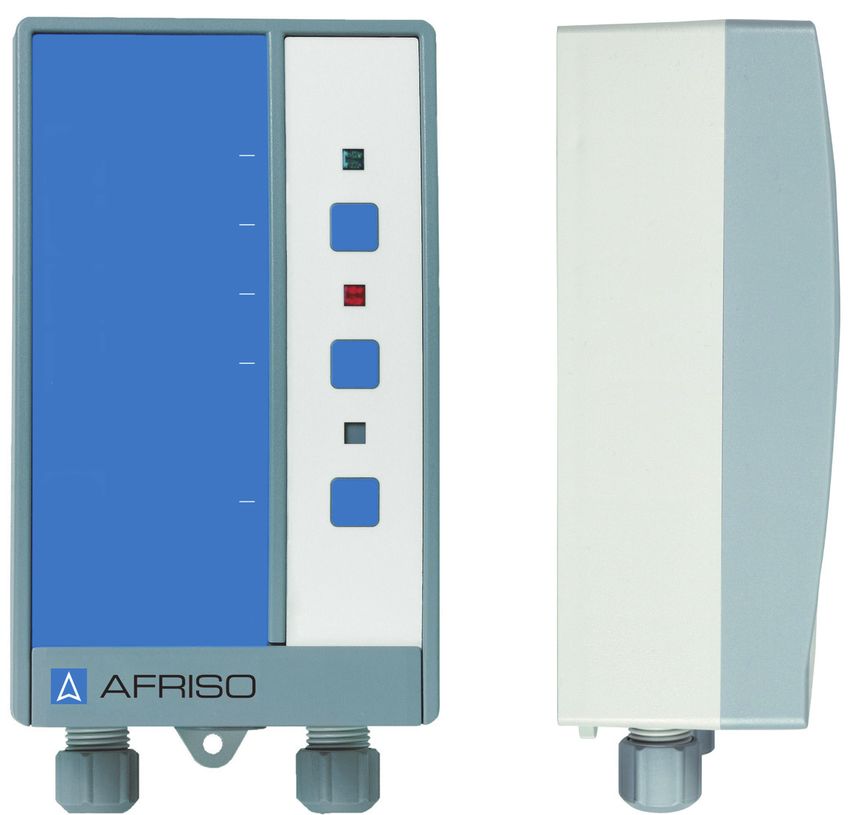
Über diese Betriebsanleitung                                    DE

1   Über diese Betriebsanleitung
    Diese Betriebsanleitung beschreibt das Wasser-Warngerät „WWG“ (im Fol-
    genden auch „Produkt“). Diese Betriebsanleitung ist Teil des Produkts.
    •   Sie dürfen das Produkt erst benutzen, wenn Sie die Betriebsanleitung
        vollständig gelesen und verstanden haben.
    •   Stellen Sie sicher, dass die Betriebsanleitung für alle Arbeiten an und mit
        dem Produkt jederzeit verfügbar ist.
    •   Geben Sie die Betriebsanleitung und alle zum Produkt gehörenden
        Unterlagen an alle Benutzer des Produkts weiter.
    •   Wenn Sie der Meinung sind, dass die Betriebsanleitung Fehler, Wider-
        sprüche oder Unklarheiten enthält, wenden Sie sich vor Benutzung des
        Produkts an den Hersteller.
    Diese Betriebsanleitung ist urheberrechtlich geschützt und darf ausschließ-
    lich im rechtlich zulässigen Rahmen verwendet werden. Änderungen vorbe-
    halten.
    Für Schäden und Folgeschäden, die durch Nichtbeachtung dieser Betriebs-
    anleitung sowie Nichtbeachten der am Einsatzort des Produkts geltenden
    Vorschriften, Bestimmungen und Normen entstehen, übernimmt der Herstel-
    ler keinerlei Haftung oder Gewährleistung.

                                                                 WWG              2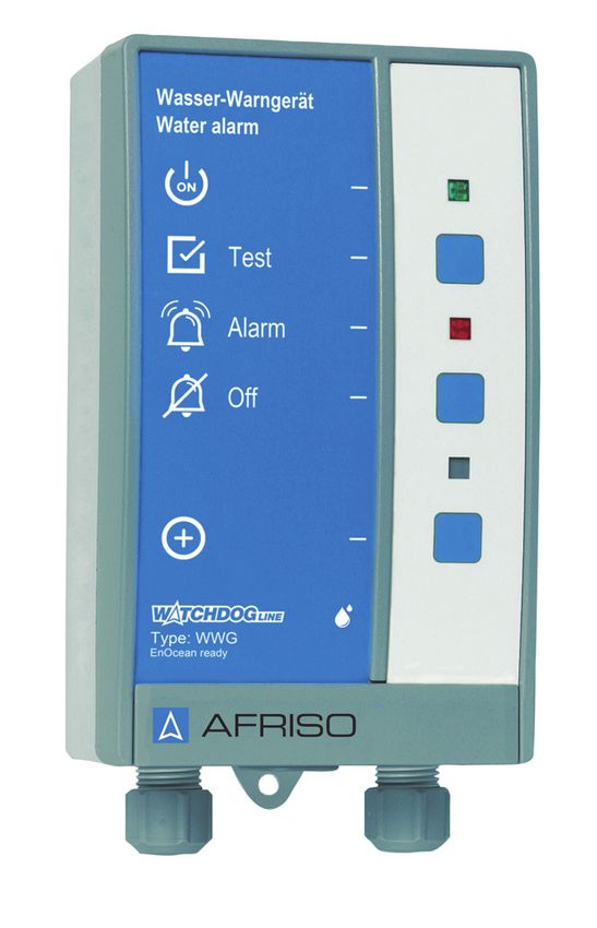
Informationen zur Sicherheit                               DE

2     Informationen zur Sicherheit
2.1   Warnhinweise und Gefahrenklassen
      In dieser Betriebsanleitung finden Sie Warnhinweise, die auf potenzielle
      Gefahren und Risiken aufmerksam machen. Zusätzlich zu den Anweisungen
      in dieser Betriebsanleitung müssen Sie alle am Einsatzort des Produktes
      geltenden Bestimmungen, Normen und Sicherheitsvorschriften beachten.
      Stellen Sie vor Verwendung des Produktes sicher, dass Ihnen alle Bestim-
      mungen, Normen und Sicherheitsvorschriften bekannt sind und dass sie
      befolgt werden.
      Warnhinweise sind in dieser Betriebsanleitung mit Warnsymbolen und Sig-
      nalwörtern gekennzeichnet. Abhängig von der Schwere einer Gefährdungs-
      situation werden Warnhinweise in unterschiedliche Gefahrenklassen unter-
      teilt.

                                      GEFAHR
      GEFAHR macht auf eine unmittelbar gefährliche Situation aufmerksam, die
      bei Nichtbeachtung unweigerlich einen schweren oder tödlichen Unfall zur
      Folge hat.

                                  HINWEIS
      HINWEIS macht auf eine möglicherweise gefährliche Situation aufmerksam,
      die bei Nichtbeachtung Sachschäden zur Folge haben kann.

      Zusätzlich werden in dieser Betriebsanleitung folgende Symbole verwendet:
                     Dies ist das allgemeine Warnsymbol. Es weist auf die
                     Gefahr von Verletzungen und Sachschäden hin. Befolgen
                     Sie alle im Zusammenhang mit diesem Warnsymbol
                     beschriebenen Hinweise, um Unfälle mit Todesfolge, Verlet-
                     zungen und Sachschäden zu vermeiden.

                     Dieses Symbol warnt vor gefährlicher elektrischer Span-
                     nung. Wenn dieses Symbol in einem Warnhinweis gezeigt
                     wird, besteht die Gefahr eines elektrischen Schlags.

                                                              WWG              3
Informationen zur Sicherheit                                 DE

2.2   Bestimmungsgemäße Verwendung
      Dieses Produkt eignet sich ausschließlich zur Detektierung von leitfähigen
      Flüssigkeiten und zur Überwachung von:
      •   Leitungsbruch
      •   Wassereinbruch von außen
      •   Zur frühzeitigen Meldung von Wasserschäden
      •   Zur frühzeitigen Meldung von Lecks, Rückstau oder Überflutungen
      •   Rückhalteeinrichtungen unter wasserverbrauchenden Geräten
      •   Domschächten, Rohr- oder Kabelkanälen
      •   Lagerung und Transport von leitfähigen Flüssigkeiten
      Das Produkt eignet sich ausschließlich für folgende Flüssigkeiten bei atmo-
      sphärischen Drücken:
      •   Grauwasser
      •   Leitungswasser, Frischwasser
      •   Wässrige Lösungen wie beispielsweise Getränke, Säuren, Laugen
      •   Frostschutzmittel, flüssige Düngemittel
      •   Leitfähige Wassergemische, Emulsionen
      Das Produkt eignet sich für leitfähige Flüssigkeiten, gegen deren Einwirkung
      die medienberührenden Teile hinreichend beständig sind:
      •   Elektroden: V2A
      •   Kunststoff: PA, PP
      •   Vergussmasse: Polyolefinbasis
      •   Kabel: Ölflex
      Eine andere Verwendung ist nicht bestimmungsgemäß und verursacht
      Gefahren.
      Stellen Sie vor Verwendung des Produkts sicher, dass das Produkt für die
      von Ihnen vorgesehene Verwendung geeignet ist. Berücksichtigen Sie dabei
      mindestens Folgendes:
      •   Alle am Einsatzort geltenden Bestimmungen, Normen und Sicherheits-
          vorschriften
      •   Alle für das Produkt spezifizierten Bedingungen und Daten
      •   Die Bedingungen der von Ihnen vorgesehenen Anwendung

                                                                 WWG               4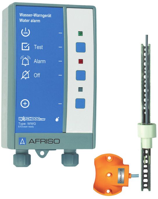
Informationen zur Sicherheit                                       DE

      Führen Sie darüber hinaus eine Risikobeurteilung in Bezug auf die konkrete,
      von Ihnen vorgesehene Anwendung nach einem anerkannten Verfahren
      durch und treffen Sie entsprechende dem Ergebnis alle erforderlichen
      Sicherheitsmaßnahmen. Berücksichtigen Sie dabei auch die möglichen Fol-
      gen eines Einbaus oder einer Integration des Produkts in ein System oder in
      eine Anlage.
      Führen Sie bei der Verwendung des Produkts alle Arbeiten ausschließlich
      unter den in der Betriebsanleitung und auf dem Typenschild spezifizierten
      Bedingungen und innerhalb der spezifizierten technischen Daten und in
      Übereinstimmung mit allen am Einsatzort geltenden Bestimmungen, Nor-
      men und Sicherheitsvorschriften durch.

2.3   Vorhersehbare Fehlanwendung
      Das Produkt darf insbesondere in folgenden Fällen und für folgende Zwecke
      nicht angewendet werden:
      •   Für Flüssigkeiten, die isolierend wirken, die zur Dickflüssigkeit neigen
          oder die zu Verklebungen und festen Ablagerungen führen.
      •   Explosionsgefährdete Umgebung
          - Bei Betrieb in explosionsgefährdeten Bereichen kann Funkenbildung zu
            Verpuffungen, Brand oder Explosionen führen.
      •   In Verbindung mit Produkten, die direkt oder indirekt menschlichen,
          gesundheits- oder lebenssichernden Zwecken dienen, oder durch deren
          Betrieb Gefahren für Mensch, Tier oder Sachwerte entstehen können.

                                                                   WWG               5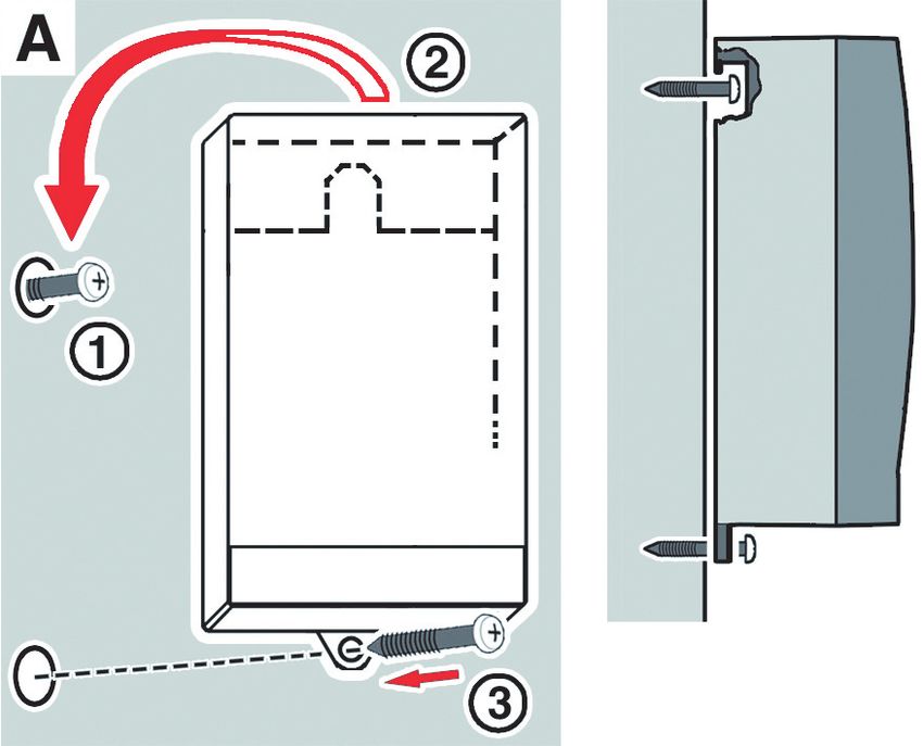
Informationen zur Sicherheit                                 DE

2.4   Qualifikation des Personals
      Arbeiten an und mit diesem Produkt dürfen nur von Fachkräften vorgenom-
      men werden, die den Inhalt dieser Betriebsanleitung und alle zum Produkt
      gehörenden Unterlagen kennen und verstehen.
      Die Fachkräfte müssen aufgrund ihrer fachlichen Ausbildung, Kenntnisse
      und Erfahrungen in der Lage sein, mögliche Gefährdungen vorherzusehen
      und zu erkennen, die durch den Einsatz des Produkts entstehen können.
      Den Fachkräften müssen alle geltenden Bestimmungen, Normen und
      Sicherheitsvorschriften, die bei Arbeiten an und mit dem Produkt beachtet
      werden müssen, bekannt sein.

2.5   Persönliche Schutzausrüstung
      Verwenden Sie immer die erforderliche persönliche Schutzausrüstung.
      Berücksichtigen Sie bei Arbeiten an und mit dem Produkt auch, dass am Ein-
      satzort Gefährdungen auftreten können, die nicht direkt vom Produkt ausge-
      hen.

2.6   Veränderungen am Produkt
      Führen Sie ausschließlich solche Arbeiten an und mit dem Produkt durch, die
      in dieser Betriebsanleitung beschrieben sind. Nehmen Sie keine Verände-
      rungen vor, die in dieser Betriebsanleitung nicht beschrieben sind.

                                                                WWG               6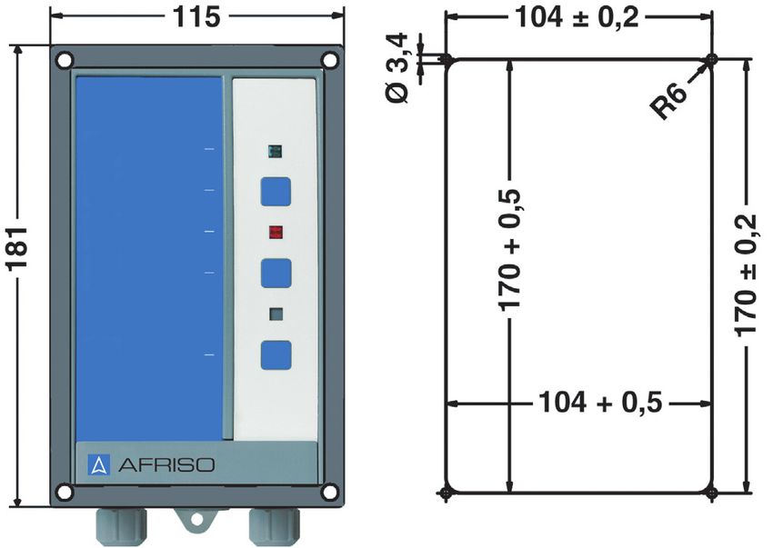
Transport und Lagerung                                  DE

3     Transport und Lagerung
      Das Produkt kann durch unsachgemäßen Transport und Lagerung beschä-
      digt werden.

                                   HINWEIS
    UNSACHGEMÄSSE HANDHABUNG
    • Stellen Sie sicher, dass während des Transports und der Lagerung des Pro-
      dukts die spezifizierten Umgebungsbedingungen eingehalten werden.
    • Benutzen Sie für den Transport die Originalverpackung.
    • Lagern Sie das Produkt nur in trockener, sauberer Umgebung.
    • Stellen Sie sicher, dass das Produkt bei Transport und Lagerung stoßge-
      schützt ist.
    Nichtbeachtung dieser Anweisungen kann zu Sachschäden führen.

                                                              WWG             7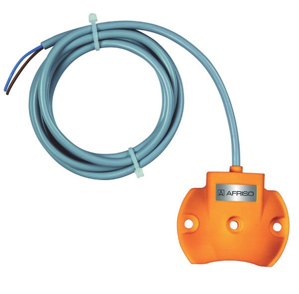
Produktbeschreibung                                    DE

4       Produktbeschreibung
4.1     Übersicht
        Das Produkt besteht aus einem Signalteil und einer Sonde. Das Signalteil
        und die Sonde sind durch ein zweiadriges Sondenkabel verbunden.
        Abhängig vom Bestellumfang ist das Signalteil mit einem EnOcean®-Funk-
        modul ausgestattet. Produkte ohne EnOcean®-Funkmodul können nachge-
        rüstet werden.

4.1.1      Signalteil
           Das Signalteil enthält in einem schlagfesten Kunststoffgehäuse die
           Anzeige- und Bedienelemente sowie sämtliche elektronische Komponen-
           ten zur Auswertung und Umformung des Sondensignals in ein digitales
           Ausgangssignal. Das Ausgangssignal steht in Form von zwei potenzial-
           freien Relaiskontakten (Wechsler) zur Verfügung.

                                               A    A. Bezeichnung des Pro-
                                                       dukts

                                               B    B. Grüne LED
                                                    C. Test-Taste
                                               C    D. Rote LED
                                               D    E. Quittiertaste
                                                    F. Ohne Funktion
                                               E
                                                    G. LRN-Taste (für En-
                                                F      Ocean®-Funkmodul)
                                                G   H. Icon aus der AFRISO-
                                                       home App
                                                H
                                                    I. Typbezeichnung des Pro-
                                                       dukts
                                                I

                                                                 WWG               8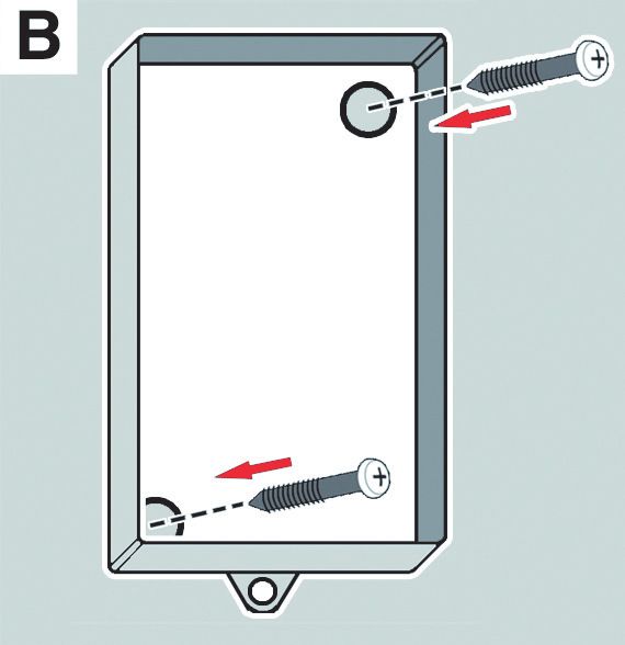
Produktbeschreibung DE
4.1.2 Bodenwassersonde „BWS 10-1“
Die Bodenwassersonde
„BWS 10-1“ wird flach an der
tiefsten Stelle der zu überwa-
chenden Bodenflächen
befestigt.
Die Sonde erkennt leitfähige
Flüssigkeiten ab einer Höhe
von 2 bis 3 mm. Die Boden-
wassersonde hat zwei Edel-
stahlelektroden und ist mit
einem zweiadrigen Sonden-
kabel versehen.
4.1.3 Wandschienensonde für „WWG 2“
Die Wandschienensonde ist
eine höhenverstellbare
Sonde mit einer Wandbefesti-
gungsschiene. Die Wand-
schienensonde hat zwei
Edelstahlelektroden und ist
mit einem zweiadrigem Son-
denkabel versehen.
WWG 9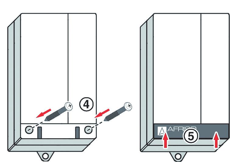
Produktbeschreibung                                      DE

4.1.4    Piktogramme
        Symbol         Bedeutung/Funktion
                       Anzeige
                       Nach Einschalten des Produkts signalisiert die grüne
                       LED rechts neben dem Symbol die Betriebsbereit-
                       schaft.

                       Taste
                       Mit der Test-Taste wird die Funktionsbereitschaft/
                       Funktionsprüfung des Produkts kontrolliert und durch-
                       geführt.

                       Anzeige
                       Die rote LED rechts neben dem Symbol signalisiert
                       einen Alarm oder eine Störung (nur bei Signalteil mit
                       EnOcean®-Funkmodul).

                       Taste
                       Mit dieser Taste wird der akustische Alarm quittiert/
                       abgeschaltet.

                       Taste
                       Mit der LRN-Taste sendet das Produkt ein Lern-Tele-
                       gramm (LRNTEL), um sich mit dem AFRISOhome
                       Gateway zu verbinden.

                                                            WWG            10
Produktbeschreibung DE
4.2 Abmessungen
65 mm
100 mm 60 mm
166 mm
188 mm
WWG 11Produktbeschreibung DE
4.3 Anwendungsbeispiel(e)
Abbildung 1: Beispiel in Waschräumen, Küchen, Kellern, Bürogebäuden, EDV-Archi-
ven, Lagerhallen, Industrieanlagen, Wasseraufbereitung, Heizräumen
WWG 12Produktbeschreibung DE
4.4 Funktion
Das Produkt kann das Auftreten von Flüssigkeitsansammlungen erkennen.
Wenn die Edelstahlelektroden der Sonde in Flüssigkeit eintauchen, erkennt
das Signalteil das veränderte Sondensignal und gibt optisch und akustisch
Alarm.
Über das Ausgangsrelais kann das Alarmsignal an zusätzliche Geräte (bei-
spielsweise Hupe oder Rundumleuchte) ausgegeben werden.
Produkte mit EnOcean®-Funkmodul
Über das AFRISOhome Gateway können im Alarmfall automatisiert Meldun-
gen verschickt werden.
4.5 Relaisausgang
Das Produkt verfügt über ein Ausgangsrelais zur Weitermeldung des Alarm-
signals an zusätzliche Geräte.
Das Produkt kann ohne und mit zusätzlichen Geräten betrieben werden, bei-
spielsweise:
• Optische und akustische Alarmgeber
• Fernmeldegeräte
• Gebäudeleittechnik
• Sonstige
Der Betriebszustand „Quittierter Alarm“ bleibt solange erhalten, bis die
Sonde nicht mehr in Flüssigkeit eingetaucht ist. Sobald die Flüssigkeit die
Sonde nicht mehr berührt, geht das Produkt in den Normalzustand über.
4.6 Zulassungsdokumente, Bescheinigungen, Erklärungen
Das Produkt entspricht:
• EMV-Richtlinie (2014/30/EU)
• Niederspannungsrichtlinie (2014/35/EU)
• RoHS-Richtlinie (2011/65/EU)
WWG 13Produktbeschreibung DE
4.7 Technische Daten
4.7.1 Signalteil
Parameter Wert
Allgemeine Daten
Abmessungen (B x H x T) 100 x 188 x 65 mm
Gewicht 0,5 kg
Emissionen/Alarmton Min. 70 dB(A)
A-bewerteter Schallpegel des akusti-
schen Alarms bei einem Abstand von
einem Meter
Ansprechverzögerung Keine
Schaltschwelle 600 kOhm
Ausgänge 1 optischer Alarm
1 akustischer Alarm
1 Ausgangsrelais Wechsler (quittierbar)
1 Ausgangsrelais Wechsler
Alarmton Min. 70 dB(A)
Umgebungsbedingungen
Umgebungstemperatur Betrieb -5 ... 55 °C
Umgebungstemperatur Lage- -10 ... 60 °C
rung
Elektrische Daten
Versorgungsspannung AC 100 .... 240 V, ±10 %,
50 ... 60 Hz
Nennleistung 1 VA
Schaltvermögen Ausgangsrelais Maximal 250 V, 2 A, ohmsche Last
Elektrische Sicherheit
Schutzklasse (EN 60730) II
Schutzart (EN 60529) IP 30
WWG 14Produktbeschreibung DE
Parameter Wert
EnOcean®-Funk
Frequenz 868,3 MHz
Sendeleistung Max. 10 mW
Reichweite Siehe Kapitel
"Ersatzteile und Zubehör"
EnOcean®- Equipment Profile (EEP) D2-A0-01
4.7.2 Bodenwassersonde „BWS 10-1“
Parameter Wert
Allgemeine Daten
Abmessungen (Ø x H) 70 x 19 mm
Platzbedarf (Ø x H) 70 x 25 mm
Gewicht 110 g
Material Sondengehäuse Kunststoff PA
Material Elektroden Edelstahl V2A
Ansprechhöhe 2 bis 3 mm
Anschlusskabel LiYY 2 x 0,5 mm²
Standardlänge 2m
Max. Länge 50 m (geschirmt)
Umgebungsbedingungen
Umgebungsbedingungen Betrieb -5 ... 55 °C
Umgebungsbedingungen Lagerung -10 ... 60 °C
WWG 15Produktbeschreibung DE
4.7.3 Wandschienensonde für WWG 2
Parameter Wert
Allgemeine Daten
Abmessungen (B x H x T) 37 x 320 x 55 mm
Platzbedarf (B x H x T) 90 x 370 x 200 mm
Gewicht 170 g
Material Sondengehäuse Kunststoff PE
Material Elektroden Edelstahl V2A
Ansprechhöhe Einstellbar über 300 mm
Anschlusskabel Ölflex 2 x 0,5 mm²
Standardlänge 1,5 m
Max. Länge 50 m (geschirmt)
Umgebungsbedingungen
Umgebungsbedingungen Betrieb -5 ... 55 °C
Umgebungsbedingungen Lagerung -10 ... 60 °C
WWG 16Montage DE
5 Montage
5.1 Montage vorbereiten
Stellen Sie sicher, dass das akustische Warnsignal des Signalteils auch
bei Umgebungsgeräuschen jederzeit wahrgenommen werden kann.
Wenn die Hörbarkeit nicht sichergestellt werden kann, muss ein Zusatz-
alarmgerät an geeigneter Stelle angebracht werden (beispielsweise das
Zusatzalarmgerät ZAG 01, die Hupe KH 1 oder die Warnlichthupe von
AFRISO).
5.2 Signalteil montieren
Befestigen Sie das Signalteil an der Wand (Variante A oder B verwenden).
Stellen Sie sicher, dass das Signalteil in Innenräumen an eine ebene,
feste und trockene Wand montiert wird.
Stellen Sie sicher, dass das Signalteil jederzeit zugänglich und einsehbar
ist.
Stellen Sie sicher, dass das Signalteil Wasser und Spritzwasser
geschützt ist.
Abbildung 2: Signalteil mit Montagerahmen für den Einbau in Schalttafeln; rechts:
Schalttafelausschnitt
WWG 17Montage DE
1. Öffnen Sie das Signalteil.
2
1
4 5
3
2 2. Befestigen Sie das
Gehäuse an der Wand
(Variante A oder B ver-
wenden). Verwenden Sie
die beiliegende Bohrscha-
blone.
1
Variante A
1. Befestigen Sie die
Schraube an der Wand.
2. Hängen Sie das Signalteil
3 ein.
3. Befestigen Sie das Signal-
teil an der Wand mit einer
Schraube an der unteren
Lasche.
WWG 18Montage DE
Variante B
1. Bohren Sie zwei Befesti-
gungslöcher Ø 5 mm
durch das Unterteil.
2. Befestigen Sie das Signal-
teil an der Wand mit den
beiliegenden Schrauben.
3. Schließen Sie das Signal-
teil wie in Kapitel "Elektri-
scher Anschluss"
beschrieben an.
2 4. Schließen Sie das Signal-
teil.
1
3
4
5
WWG 19Montage DE
5.3 Sonde montieren
Stellen Sie sicher, dass die Sonde schon bei geringen Flüssigkeitsmen-
gen in die Flüssigkeit eintaucht und somit frühzeitig einen Alarm auslöst.
1. Schrauben Sie die Bodenwassersonde am tiefsten Punkt der zu überwa-
chenden Fläche mit den beiliegenden Schrauben an, oder beschweren
die Bodenwassersonde mit einem geeigneten Gewicht.
2. Befestigen Sie die Wandschienensonde mit zwei Schrauben in der
gewünschten Höhe an einer Wand.
Der Sondenkörper ist in der Schiene höhenverstellbar.
1. Lösen Sie die Schraube über dem Sondenkörper.
2. Stellen Sie den Sondenkörper auf die entsprechende Höhe ein und zie-
hen Sie die Schraube wieder fest.
5.4 Gummitülle durch Kabelverschraubung ersetzen
Bei einem fest verlegten
Kabel kann die am Produkt
vorhandene mittlere Gummi-
tülle verwendet werden.
M16 M16
M20
WWG 20Montage DE
5.5 Elektrischer Anschluss
GEFAHR
ELEKTRISCHER SCHLAG
• Stellen Sie sicher, dass durch die Art der elektrischen Installation der Schutz
gegen elektrischen Schlag (Schutzklasse, Schutzisolierung) nicht vermin-
dert wird.
• Stellen Sie sicher, dass das Produkt mit einer fest verlegten Leitung ange-
schlossen wird.
Nichtbeachtung dieser Anweisungen führt zu Tod oder schweren Verlet-
zungen.
GEFAHR
ELEKTRISCHER SCHLAG DURCH SPANNUNGSFÜHRENDE TEILE
• Unterbrechen Sie vor Beginn der Arbeiten die Netzspannung und sichern
Sie diese gegen Wiedereinschalten.
• Stellen Sie sicher, dass durch elektrisch leitfähige Gegenstände oder
Medien keine Gefährdungen ausgehen können.
Nichtbeachtung dieser Anweisungen führt zu Tod oder schweren Verlet-
zungen.
HINWEIS
NICHTVERFÜGBARKEIT DER ÜBERWACHUNGSFUNKTION
• Installieren Sie keine Netzstecker oder Schalter in der Spannungsversor-
gung für das Produkt.
• Schalten Sie das Produkt nur über die bauseitige Netzsicherung ein und aus.
Nichtbeachtung dieser Anweisungen kann zu Sachschäden führen.
WWG 21Montage DE
A. Versorgungsspannung
F AC 100 - 240 V
B. Ausgangsrelais
(quittierbar)
C. Ausgangsrelais
B (nicht quittierbar)
D E
A D. Externe Quittierung
E. Sonde (konduktive)
C F. Steckplatz für das
EnOcean®-Funkmodul
5.5.1 Spannungsversorgung
Stellen Sie sicher, dass der Netzanschluss des Produkts mit einer fest
verlegten, geeigneten Leitung (beispielsweise H0H5VV-F 2 x 1 mm²)
an die Spannungsversorgung angeschlossen wird.
Stellen Sie sicher, dass die Zuleitung zum Signalteil separat mit maxi-
mal 16 A abgesichert ist.
1. Führen Sie das Netzkabel durch die linke Kabelverschraubung in das
Signalteil ein.
2. Schließen Sie die Phase an die Klemme L und den Neutralleiter an die
Klemme N an.
- Der Schutzleiter muss nicht angeschlossen werden.
5.5.2 Sonde
Stellen Sie sicher, dass das Sondenkabel gegen Beschädigungen
geschützt wird (beispielsweise in Metallrohr verlegen).
Stellen Sie sicher, dass das Sondenkabel nicht direkt neben oder
zusammen mit Kabeln verlegt wird, die Netzspannung führen.
1. Verlegen Sie das Sondenkabel.
2. Führen Sie das Sondenkabel durch die rechte Kabelverschraubung in
das Signalteil.
3. Schließen Sie das Sondenkabel an die Klemmen mit der Bezeichnung
„Sonde“ an. Die Polarität ist beliebig.
WWG 22Montage DE
Als Verlängerung des Sondenkabels kann eine handelsübliche
geschirmte Leitung (2 x 1,0 mm²) verwendet werden. Die maximale
Länge der Verlängerung beträgt 50 m.
5.5.3 Extern quittieren
An die zwei Klemmen im Signalteil mit der Bezeichnung „externe Quit.“
kann in bis zu 100 m Entfernung ein Taster (Schließer) zur externen Quit-
tierung des Produkts angeschlossen werden. Die maximale Spannung an
diesen Klemmen beträgt 12 V. Die Tasteranschlüsse müssen potenzial-
frei sein.
5.5.4 Ausgänge
Das Ausgangssignal des Signalteils wird über zwei potentialfreie Relais-
kontakte (Wechsler) ausgegeben. Im Normalbetrieb sind die Relais abge-
fallen. Im Alarmfall ziehen beide Relais an. Wenn während dem Alarmfall
die Off-Taste betätigt wird, fällt ein Relais ab.
5.6 Nachrüstung eines EnOcean®-Funkmoduls (optional)
GEFAHR
ELEKTRISCHER SCHLAG DURCH SPANNUNGSFÜHRENDE TEILE
• Unterbrechen Sie vor Beginn der Arbeiten die Netzspannung und sichern
Sie diese gegen Wiedereinschalten.
Nichtbeachtung dieser Anweisungen führt zu Tod oder schweren Verlet-
zungen.
HINWEIS
ELEKTROSTATISCHE ENTLADUNG
• Erden Sie sich immer, bevor Sie die elektronischen Bauteile berühren.
• Berühren Sie beim Einsetzen nicht das EnOcean®-Funkmodul, sondern set-
zen Sie es mit Hilfe der anti-elektrostatischen Folie in den Steckplatz ein.
Nichtbeachtung dieser Anweisungen kann zu Sachschäden führen.
WWG 23Montage DE
1. Öffnen Sie das Signalteil.
A. Steckplatz für das EnO-
cean®-Funkmodul
A
2. Stecken Sie das EnO-
cean®-Funkmodul in den
Steckplatz ein.
A Stellen Sie beim Einset-
zen Folgendes sicher:
- Alle Pins müssen in die
Buchsenleiste gesteckt
sein.
- Die Antenne muss auf
der rechten Seite ent-
lang der Gehäusewand
in die Führung (A)
geklemmt sein.
3. Schließen Sie den Deckel
des Signalteils wieder.
WWG 24Inbetriebnahme DE
6 Inbetriebnahme
6.1 Produkt mit AFRISOhome Gateway verbinden (optional)
Der Einlernvorgang ist in der Betriebsanleitung des AFRISOhome Gateways
oder der App beschrieben.
Stellen Sie sicher, dass das Signalteil ordnungsgemäß elektrisch ange-
schlossen wurde (siehe Kapitel "Elektrischer Anschluss").
Stellen Sie sicher, dass das AFRISOhome Gateway sich in der Nähe des
Signalteils befindet.
Stellen Sie sicher, dass das AFRISOhome Gateway sich im „Einlern-
Modus“ befindet.
1. Schalten Sie die Netzspannung ein.
- Die grüne LED leuchtet.
2. Drücken Sie die untere Taste einmal.
- Das Produkt sendet ein Lern-Telegramm (LRNTEL).
- Das Produkt ist mit dem AFRISOhome Gateway verbunden.
3. Beachten Sie die Anweisungen/Informationen in der App.
6.2 Funktionsprüfung
6.2.1 An der Sonde
Stellen Sie sicher, dass die zu detektierende Flüssigkeit bei allen am
Installationsort auftretenden Temperaturen erkannt wird.
1. Tauchen Sie die Sonde in die zu überwachende Flüssigkeit.
- Die rote LED leuchtet und der akustische Alarm ertönt.
2. Drücken Sie die Quittiertaste am Signalteil.
- Der akustische Alarm verstummt.
- Die rote LED leuchtet.
3. Nehmen Sie die Sonde aus der Flüssigkeit.
- Die rote LED erlischt.
6.2.2 Am Signalteil
1. Drücken Sie die Test-Taste.
- Die rote LED leuchtet und der akustische Alarm ertönt.
2. Lassen Sie die Test-Taste los, um die Funktionsprüfung am Signalteil
zu beenden.
WWG 25Betrieb DE
7 Betrieb
Die Bedienung des Produkts beschränkt sich auf dessen regelmäßige Über-
wachung:
• Die grüne LED leuchtet.
• Die rote LED leuchtet nicht.
7.1 Alarm
Wenn die Sonde Flüssigkeit detektiert, ändert sich das elektrische Aus-
gangssignal der Sonde und das Signalteil gibt Alarm.
• Die rote LED leuchtet.
• Der akustische Alarm ertönt.
Über den Relaisausgang wird das Alarmsignal an zusätzliche Geräte ausge-
geben.
Bei Produkten mit EnOcean®-Funkmodul verschickt das Signalteil eine Mel-
dung an das AFRISOhome Gateway. Über die AFRISO App erhält der End-
anwender eine Meldung, dass eine Flüssigkeitsansammlung detektiert
wurde.
7.1.1 Alarm quittieren
1. Drücken Sie die Quittiertaste am Signalteil.
- Der akustische Alarm verstummt.
- Die rote LED leuchtet weiter.
Bei Spannungsausfall
Bei Ausfall der Spannungsversorgung wird kein Alarm ausgelöst. Bei
Wiederkehr der Spannungsversorgung ist das Produkt sofort betriebsbe-
reit. Wenn inzwischen ein Leckagefall aufgetreten ist, gibt das Produkt
nach Wiederkehr der Spannungsversorgung Alarm.
7.1.2 Nach einem Alarm
Nach einem Alarm muss die Sonde auf Verschmutzung hin geprüft wer-
den.
Stellen Sie sicher, dass sich keine Reste der Flüssigkeit oder Ablage-
rungen an der Sonde befinden.
1. Entfernen Sie Flüssigkeitsreste.
2. Reinigen Sie die Sonde vorsichtig mit einem trockenen, fusselfreien
Tuch.
3. Führen Sie eine Funktionsprüfung durch.
WWG 26Wartung DE
8 Wartung
8.1 Wartungsintervalle
Wann Tätigkeit
Einmal jährlich und nach Führen Sie eine Sichtprüfung der Sonde durch
Alarmfall (siehe "Nach einem Alarm").
Tauschen Sie beschädigte Teile.
Führen Sie eine Funktionsprüfung durch
("Funktionsprüfung").
1 x halbjährlich Prüfen Sie die Funkverbindung (siehe 6.2.1 und
7.1) mit der App.
9 Störungsbeseitigung
Das Produkt darf nur vom Hersteller repariert werden.
Problem Mögliche Ursache Fehlerbehebung
Grüne LED leuchtet Keine Versorgungs- Stellen Sie die Versor-
nicht spannung gungsspannung her
Flachbandleitung nicht Verbinden Sie die Flach-
mit Leiterplatte verbun- bandleitung mit der Lei-
den terplatte
Rote LED blinkt und der Kurzschluss in der Prüfen oder tauschen
akustische Alarm ertönt, Sonde Sie die Sonde
auch wenn die Sonde Leitungsunterbrechung Prüfen Sie das Sonden-
nicht in Flüssigkeit ist in der Sonde kabel
Betätigung der Test- Signalteil ist defekt Tauschen Sie das Sig-
Taste bleibt ohne Wir- nalteil aus
kung
Sonstige Störungen - Bitte wenden Sie sich
an die AFRISO-Service
Hotline
10 Außerbetriebnahme und Entsorgung
Entsorgen Sie das Produkt nach den geltenden Bestimmungen, Normen und
Sicherheitsvorschriften.
WWG 27Rücksendung DE
Elektronikteile dürfen nicht mit dem Hausmüll entsorgt werden.
1. Trennen Sie das Produkt von der Versorgungsspannung.
2. Demontieren Sie das Produkt (siehe Kapitel "Montage"
in umgekehrter Reihenfolge).
3. Entsorgen Sie das Produkt.
11 Rücksendung
Vor einer Rücksendung Ihres Produkts müssen Sie sich mit uns in Verbin-
dung setzen (service@afriso.de).
12 Gewährleistung
Informationen zur Gewährleistung finden Sie in unseren Allgemeinen
Geschäftsbedingungen im Internet unter www.afriso.com oder in Ihrem Kauf-
vertrag.
13 Ersatzteile und Zubehör
HINWEIS
UNGEEIGNETE TEILE
• Verwenden Sie nur Original Ersatz- und Zubehörteile des Herstellers.
Nichtbeachtung dieser Anweisung kann zu Sachschäden führen.
Produkt
Artikelbezeichnung Art.-Nr. Abbildung
Wasser-Warngerät 40032
„WWG“ (Signalteil)
Wasser-Warngerät 40029
„WWG 1“ (Signalteil mit
Bodenwassersonde)
Wasser-Warngerät 40031
„WWG 2“ (Signalteil mit
Wandschienensonde)
WWG 28Informationen zu EnOcean®-Funk DE
Ersatzteile und Zubehör
Artikelbezeichnung Art.-Nr. Abbildung
Bodenwassersonde 55112
„BWS 10-1“
Wandschienensonde 55050
Kabelverlängerungsarma- 40041 -
tur KVA
Montagerahmen für Signal- 43521 -
teil
IP 54-Set mit Kabelver- 43416 -
schraubung M 20
EnOcean®-Funkmodul 78082 -
TCM 320
14 Informationen zu EnOcean®-Funk
14.1 Reichweiten des EnOcean®-Funks
Weiterführende Informationen zur Reichweitenplanung mit EnOcean® fin-
den Sie auf www.enocean.com.
14.2 Weiterführende Informationen zu EnOcean®-Funksystemen
WWG 29Informationen zu EnOcean®-Funk DE
Weiterführende Informationen zu Planung, Installation und Betrieb von
EnOcean®-Funksystemen finden Sie auf www.enocean.com.
• Funkstandard
• Funktechnologie
• AN001
• AN102
• AN103
14.3 Möglichkeiten der EnOcean®-Technologie
Unterlagen über EnOcean®-Technologien finden Sie im Internet unter
www.afrisohome.de.
Auf unserem YouTube-Channel finden Sie eine Reihe von Videos zu
AFRISO-Produkten.
WWG 30Anhang DE
15 Anhang
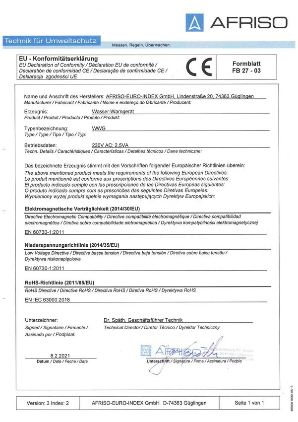
15.1 EU-Konformitätserklärung
WWG 31Operating
instructions
Water alarm unit
WWG
Type: WWG
Type: WWG 1
Type: WWG 2
Copyright 2021 AFRISO-EURO-INDEX GmbH. All rights reserved.
Lindenstraße 20
74363 Güglingen
Telephone +49 7135 102-0
Service +49 7135 102-211
Telefax +49 7135 102-147
info@afriso.com
Version: 02.2021.0
www.afriso.com
ID: 900.000.0279About these operating instructions EN
1 About these operating instructions
These operating instructions describe the water alarm unit "WWG" (also
referred to as "product" in these operating instructions). These operating
instructions are part of the product.
• You may only use the product if you have fully read and understood these
operating instructions.
• Verify that these operating instructions are always accessible for any type
of work performed on or with the product.
• Pass these operating instructions as well as all other product-related doc-
uments on to all owners of the product.
• If you feel that these operating instructions contain errors, inconsisten-
cies, ambiguities or other issues, contact the manufacturer prior to using
the product.
These operating instructions are protected by copyright and may only be
used as provided for by the corresponding copyright legislation. We reserve
the right to modifications.
The manufacturer shall not be liable in any form whatsoever for direct or con-
sequential damage resulting from failure to observe these operating instruc-
tions or from failure to comply with directives, regulations and standards and
any other statutory requirements applicable at the installation site of the prod-
uct.
WWG 2Information on safety EN
2 Information on safety
2.1 Safety messages and hazard categories
These operating instructions contain safety messages to alert you to poten-
tial hazards and risks. In addition to the instructions provided in these oper-
ating instructions, you must comply with all directives, standards and safety
regulations applicable at the installation site of the product. Verify that you are
familiar with all directives, standards and safety regulations and ensure com-
pliance with them prior to using the product.
Safety messages in these operating instructions are highlighted with warning
symbols and warning words. Depending on the severity of a hazard, the
safety messages are classified according to different hazard categories.
DANGER
DANGER indicates a hazardous situation, which, if not avoided, will result in
death or serious injury.
NOTICE
NOTICE indicates a hazardous situation, which, if not avoided, can result in
equipment damage.
In addition, the following symbols are used in these operating instructions:
This is the general safety alert symbol. It alerts to injury haz-
ards or equipment damage. Comply with all safety instruc-
tions in conjunction with this symbol to help avoid possible
death, injury or equipment damage.
This symbol alerts to hazardous electrical voltage. If this
symbol is used in a safety message, there is a hazard of
electric shock.
WWG 3Information on safety EN
2.2 Intended use
The product may only be used to detect conductive liquids and only to mon-
itor:
• Pipes for leakage
• Water ingress from the outside
• For early indication of water damage
• Leaks, backflow or flooding
• Collection facilities below devices consuming water
• Manholes, pipe and cable ducts
• Storage and transport of conductive liquids
The product may only be used for the following liquids at atmospheric pres-
sure:
• Grey water
• Mains water, fresh water
• Aqueous solutions such as beverages, acids, bases
• Antifreeze agents, liquid fertilisers
• Conductive water mixtures, emulsions
The product is suitable for conductive liquids to which the following wetted
parts are sufficiently resistant:
• Electrodes: V2A
• Plastic: PA, PP
• Sealing material: Polyolefin base
• Cable: Ölflex
Any use other than the application explicitly permitted in these operating
instructions is not permitted and causes hazards.
Verify that the product is suitable for the application planned by you prior to
using the product. In doing so, take into account at least the following:
• All directives, standards and safety regulations applicable at the installa-
tion site of the product
• All conditions and data specified for the product
• The conditions of the planned application
WWG 4Information on safety EN
In addition, perform a risk assessment in view of the planned application,
according to an approved risk assessment method, and implement the
appropriate safety measures, based on the results of the risk assessment.
Take into account the consequences of installing or integrating the product
into a system or a plant.
When using the product, perform all work and all other activities in conjunc-
tion with the product in compliance with the conditions specified in the oper-
ating instructions and on the nameplate, as well as with all directives, stand-
ards and safety regulations applicable at the installation site of the product.
2.3 Predictable incorrect application
The product must never be used in the following cases and for the following
purposes:
• For liquids with an insulating effect as well as liquids which tend to
become highly viscous or which lead to agglutinations or deposits.
• Hazardous area (EX)
- If the product is operated in hazardous areas, sparks may cause defla-
grations, fires or explosions.
• In conjunction with products which are used for health-saving or life-sav-
ing purposes or whose operation may incur hazards to humans, animals
or property.
2.4 Qualification of personnel
Only appropriately trained persons who are familiar with and understand the
contents of these operating instructions and all other pertinent product doc-
umentation are authorized to work on and with this product.
These persons must have sufficient technical training, knowledge and expe-
rience and be able to foresee and detect potential hazards that may be
caused by using the product.
All persons working on and with the product must be fully familiar with all
directives, standards and safety regulations that must be observed for per-
forming such work.
WWG 5Information on safety EN
2.5 Personal protective equipment
Always wear the required personal protective equipment. When performing
work on and with the product, take into account that hazards may be present
at the installation site which do not directly result from the product itself.
2.6 Modifications to the product
Only perform work on and with the product which is explicitly described in
these operating instructions. Do not make any modifications to the product
which are not described in these operating instructions.
WWG 6Transport and storage EN
3 Transport and storage
The product may be damaged as a result of improper transport or storage.
NOTICE
INCORRECT HANDLING
• Verify compliance with the specified ambient conditions during transport or
storage of the product.
• Use the original packaging when transporting the product.
• Store the product in a clean and dry environment.
• Verify that the product is protected against shocks and impact during trans-
port and storage.
Failure to follow these instructions can result in equipment damage.
WWG 7Product description EN
4 Product description
4.1 Overview
The product consists of a control unit and a probe. The control unit and the
probe are connected by means of a two-wire probe cable.
Depending on the order, the control unit is equipped with an EnOcean® wire-
less module. Products without an EnOcean® wireless module can be retro-
fitted.
4.1.1 Control unit
The control unit contains the following elements in an impact-resistant
plastic housing: display elements and controls as well as all electronic
components for signal processing and conversion of the probe signal into
a digital output signal. The output signal is available via two voltage-free
relay contacts (changeover contacts).
A A. Designation of product
B. Green LED
B C. Test key
D. Red LED
C E. Acknowledge button
D F. Without function
E G. LRN key (for EnOcean®
wireless module)
F
H. Icon from AFRISOhome
G app
I. Type designation of the
H
product
i
WWG 8Product description EN
4.1.2 Floor water probe "BWS 10-1"
The floor water probe
"BWS 10-1" is fastened at the
lowest point of the floor sur-
face to be monitored.
The probe detects conductive
liquids at a level of 2 to 3 mm.
The floor water probe has two
stainless steel electrodes; it
is fitted with a two-wire probe
cable.
4.1.3 Wall mounting rail probe for "WWG 2"
The wall mounting rail probe
is a height-adjustable probe
with a rail mounted to a wall.
The wall mounting probe has
two stainless steel electrodes
and a two-wire probe cable.
WWG 9Product description EN
4.1.4 Pictograms
Symbol Meaning/function
Indication
When power is supplied to the product, the green LED
next to the symbol indicates that the product is ready
for operation.
Key
The Test key allows you to perform the function test of
the product and verify correct operation.
Indication
The red LED to the right of the symbol indicates an
alarm or an error (only control unit EnOcean® wire-
less module).
Key
This key allows you to acknowledge and mute the
audible alarm.
Key
If the LRN key is pressed, the product sends a LRN
telegram (LRNTEL) to connect to the AFRISOhome
gateway.
WWG 10Product description EN
4.2 Dimensions
65 mm
100 mm 60 mm
166 mm
188 mm
WWG 11Product description EN
4.3 Application example(s)
Fig. 1: Examples in laundry rooms, kitchens, basements, office buildings, IT rooms,
storehouses, industrial facilities, water treatment, boiler rooms
WWG 12Product description EN
4.4 Function
The product can detect accumulations of liquids. If the stainless steel elec-
trodes of the probes are submerged in liquid, the control unit detects the
change in the probe signal and generates visual and audible alarms.
The alarm signal can be transmitted to additional equipment (for example,
horn or warning light with rotating reflector) via the output relay.
Products with EnOcean® wireless module
The AFRISOhome gateway allows for automatic transmission of messages
in the case of an alarm.
4.5 Relay output
The product is equipped with an output relay to transmit the alarm signal to
additional equipment.
The product can be operated with or without additional equipment, for exam-
ple:
• Visual and audible alarm units
• Remote alarm equipment
• Building control systems
• Other
The operating state "Acknowledged alarm" remains active until the probe is
no longer submerged in the liquid. As soon as the probe is no longer sub-
merged in the liquid, the product resumes normal operation.
4.6 Approvals, conformities, certifications
The product complies with:
• EMC Directive (2014/30/EU)
• Low Voltage Directive (2014/35/EU)
• RoHS Directive (2011/65/EU)
WWG 13Product description EN
4.7 Technical data
4.7.1 Control unit
Parameter Value
General specifications
Dimensions (W x H x D) 100 x 188 x 65 mm
Weight 0.5 kg
Emission/alarm sound Min. 70 dB(A)
A-weighted sound level of the audible
alarm at a distance of one metre
Response delay None
Switching threshold 600 kOhm
Outputs 1 visual alarm
1 audible alarm
1 output relay changeover contact (can be
acknowledged)
1 output relay changeover contact
Alarm sound Min. 70 dB(A)
Ambient conditions
Ambient temperature operation -5 ... 55 °C
Ambient temperature storage -10 ... 60 °C
Electrical data
Supply voltage AC 100 .... 240 V, ±10 %,
50 ... 60 Hz
Nominal power 1 VA
Breaking capacity output relay 250 V maximum, 2 A, resistive load
Electrical safety
Protection class (EN 60730) II
Degree of protection (EN 60529) IP 30
WWG 14Product description EN
Parameter Value
EnOcean® wireless
Frequency 868.3 MHz
Transmission power Max. 10 mW
Range See chapter
"Spare parts and accesso-
ries"
EnOcean® Equipment Profile (EEP) D2-A0-01
4.7.2 Floor water probe "BWS 10-1"
Parameter Value
General specifications
Dimensions (Ø x H) 70 x 19 mm
Space requirements (Ø x H) 70 x 25 mm
Weight 110 g
Material probe housing Plastic PA
Material electrodes Stainless steel V2A
Response level 2 to 3 mm
Connection cable LiYY 2 x 0.5 mm²
Standard length 2m
Max. length 50 m (shielded)
Ambient conditions
Ambient conditions operation -5 ... 55 °C
Ambient conditions storage -10 ... 60 °C
WWG 15Product description EN
4.7.3 Wall mounting rail probe for WWG 2
Parameter Value
General specifications
Dimensions (W x H x D) 37 x 320 x 55 mm
Space requirements (W x H x D) 90 x 370 x 200 mm
Weight 170 g
Material probe housing Plastic PE
Material electrodes Stainless steel V2A
Response level Adjustable, range 300 mm
Connection cable Ölflex 2 x 0.5 mm²
Standard length 1.5 m
Max. length 50 m (shielded)
Ambient conditions
Ambient conditions operation -5 ... 55 °C
Ambient conditions storage -10 ... 60 °C
WWG 16Mounting EN
5 Mounting
5.1 Preparing mounting
Verify that the audible alarm signal of the control unit can always be heard,
even in the case of ambient noise.
If audibility cannot be ensured, you must install an additional alarm unit at a
suitable location in the building (for example, additional alarm unit ZAG 01,
horn KH 1 or combined alarm light and horn from AFRISO).
5.2 Mounting the control unit
Mount the control unit to the wall using mounting type A or B.
Verify that the control unit is mounted to an even, rigid and dry indoor wall
at eye level.
Verify that the control unit is accessible and easy to oversee at all times.
Verify that the control unit is protected against water and splash water.
Fig. 2: Control unit with mounting frame for panel mounting; right: control panel cut out
WWG 17Mounting EN
1. Open the control unit.
2
1
4 5
3
2 2. Mount the housing to the
wall using mounting type
A or B. Use the enclosed
drilling template.
Mounting type A
1
1. Mount the screw to the
wall.
2. Fit the control unit.
3. Fasten the control unit by
screwing the bottom lug to
3 the wall.
WWG 18Mounting EN
Mounting type B
1. Drill two fixing holes with a
Ø 5 mm into the base.
2. Mount the control unit to
the wall with the enclosed
screws.
3. Connect the control unit
as described in chapter
"Electrical connection".
2 4. Close the control unit.
1
3
4
5
WWG 19Mounting EN
5.3 Mounting the probe
Verify that the probe is submerged even in the case of small amounts of
liquid so that it triggers the alarm as early as possible.
1. Fasten the floor water probe at the lowest point of the area to be moni-
tored using the enclosed screws or a suitable weight.
2. Fasten the wall mounting rail probe to the wall at the desired level using
two screws.
The height of the probe body can be adjusted in the rail.
1. Loosen the screw above the probe body.
2. Move the probe body to the desired level and tighten the screw.
5.4 Replacing the rubber piece by a cable gland
In the case of a permanently
installed cable, you can use
the centre rubber piece
M16 M16
M20
WWG 20Mounting EN
5.5 Electrical connection
DANGER
ELECTRIC SHOCK
• Verify that the degree of protection against electric shock (protection class,
double insulation) is not reduced by the type of electrical installation.
• Verify that the product is connected by means of a permanently installed
cable connection.
Failure to follow these instructions will result in death or serious injury.
DANGER
ELECTRIC SHOCK CAUSED BY LIVE PARTS
• Disconnect the mains voltage supply before performing the work and ensure
that it cannot be switched on.
• Verify that no hazards can be caused by electrically conductive objects or
media.
Failure to follow these instructions will result in death or serious injury.
NOTICE
UNAVAILABLE MONITORING FUNCTION
• Do not install mains plugs or switches in the supply line to the product.
• Only power on/power off the product via the on-site mains fuse.
Failure to follow these instructions can result in equipment damage.
WWG 21Mounting EN
A. Supply voltage
F AC 100 - 240 V
B. Output relay
(can be acknowledged)
C. Output relay
B (cannot be acknowl-
D E edged)
A
D. External acknowledge-
ment
C E. Probe (conductivity)
F. Slot for EnOcean®
wireless module
5.5.1 Supply voltage
Verify that the product is connected to mains by means of a suitable,
permanently installed cable (for example H0H5VV-F 2 x 1 mm²).
Verify that the power supply to the control unit is separately fused (16 A
maximum).
1. Route the mains cable through the left cable gland into the control unit.
2. Connect the phase to terminal L and the neutral conductor to
terminal N.
- The protective ground conductor (PE) does not have to be connected.
5.5.2 Probe
Verify that the probe cable is sufficiently protected from damage, for
example by installing it in a metal pipe.
Verify that the probe cable is not routed immediately next to or together
with cables carrying mains voltage.
1. Install the probe cable.
2. Route the probe cable into the control unit through the cable gland at
the right.
3. Connect the probe cable to the terminals with the designation "Sonde"
(probe). Any polarity is permissible.
Standard shielded cable (2 x 1.0 mm²) can be used to extend the probe
cable. The maximum length of the extension cable is 50 m.
WWG 22Mounting EN
5.5.3 External acknowledgement
A pushbutton (normally open contact) can be connected to the two termi-
nals in the control unit with the designation "externe Quit." for external
acknowledgement of alarms from a maximum distance of 100 m from the
product. The maximum voltage at these terminals is 12 V. The pushbutton
connections must be voltage-free.
5.5.4 Outputs
The output signal of the control unit is made available via two voltage-free
relay contacts (changeover contacts). During normal operation, the relays
are de-energised. In the case of an alarm, both relays are energised. If
the "Off" pushbutton is pressed during an alarm, one relay is de-ener-
gised.
5.6 Retrofitting an EnOcean® wireless module (optional)
DANGER
ELECTRIC SHOCK CAUSED BY LIVE PARTS
• Disconnect the mains voltage supply before performing the work and ensure
that it cannot be switched on.
Failure to follow these instructions will result in death or serious injury.
NOTICE
ELECTROSTATIC DISCHARGE
• Always earth yourself before touching electronic components.
• Do not touch the EnOcean® wireless module to plug it in; use the anti-elec-
trostatic film to plug it into the slot.
Failure to follow these instructions can result in equipment damage.
WWG 23Mounting EN
1. Open the control unit.
A. Slot for EnOcean® wire-
less module
A
2. Plug the EnOcean® wire-
less module into the slot.
When plugging in the
A wireless module, ensure
the following:
- All pins must be inserted
into the female connec-
tor.
- The antenna must be
located in the guide (A)
along the housing wall.
3. Close the cover of the
control unit.
WWG 24Commissioning EN
6 Commissioning
6.1 Connecting the product to an AFRISOhome gateway (optional)
See the operating instructions of the AFRISOhome gateway or the app for
detailed information on establishing a wireless connection.
Verify correct electrical connection of the control unit (see chapter "Elec-
trical connection").
Verify that AFRISOhome gateway is in the vicinity of the product.
Verify that the AFRISOhome gateway is in "Learn" mode.
1. Apply mains voltage.
- The green LED is on.
2. Briefly press the lower key once.
- The product sends a Learn telegram (LRNTEL).
- The product is now connected to the AFRISOhome gateway.
3. Note the instructions/information in the app.
6.2 Function test
6.2.1 At the probe
Verify that the liquid to be detected is detected at all temperatures that
may be present at the installation site.
1. Submerge the probe into the liquid to be detected.
- The red LED lights up and the audible alarm sounds.
2. Press the acknowledge key at the control unit.
- The audible alarm is switched off.
- The red LED lights.
3. Remove the probe from the liquid.
- The red LED goes off.
6.2.2 At the control unit
1. Press the Test key
- The red LED lights up and the audible alarm sounds.
2. Release the Test key to terminate the function test at the control unit.
WWG 25Operation EN
7 Operation
Operating the product is limited to its regular monitoring:
• The green LED is on
• The red LED is off
7.1 Alarm
If the probe detects liquid, the electrical output signal of the probe changes
and the control unit triggers an alarm.
• The red LED lights.
• The audible alarm sounds.
The alarm signal is transmitted to additional equipment via the relay output.
In the case of products with an EnOcean® wireless module, the control unit
sends a message to the AFRISOhome gateway. The user receives a mes-
sage from the AFRISO app that liquid has been detected.
7.1.1 Acknowledging an alarm
1. Press the acknowledge key at the control unit.
1. The audible alarm is switched off.
- The red LED remains lit.
Power outage
No alarm is triggered in case of a power outage. When mains voltage is
restored, the product immediately resumes operation. If, during the power
outage, leakage has occurred, the product triggers an alarm once power
is available again.
7.1.2 After an alarm
After an alarm, the probe must be checked for pollution.
Verify that there are no remainders of the liquid or deposits on the
probe.
1. Remove remainders of liquid.
2. Carefully clean the probe with a dry, lint-free cloth.
3. Perform a function test.
WWG 26Maintenance EN
8 Maintenance
8.1 Maintenance intervals
When Activity
Once per year and after Perform a visual inspection of the probe (see
an alarm "After an alarm").
Replace damaged parts.
Perform a function test ("Function test").
Every six months Check the wireless connection by using the app
(see At the probe and Alarm).
9 Troubleshooting
The product repairs by the manufacturer company.
Problem Possible reason Repair
Green LED is not on No supply voltage Apply supply voltage
Flat cable not con- Connect the flat cable to
nected to printed circuit the printed circuit board
board
Red LED flashes and Short circuit in the probe Check the probe or
the audible alarm replace it
sounds even though the Line interruption in the Check the probe cable
probe is not in liquid
probe
Pressing the Test key Control unit is defective Replace the control unit
has no effect
Other malfunctions - Contact the AFRISO
service hotline
WWG 27Decommissioning, disposal EN
10 Decommissioning, disposal
Dispose of the product in compliance with all applicable directives, standards
and safety regulations.
Electronic components must not be disposed of together with the normal
household waste.
1. Disconnect the product from mains.
2. Dismount the product (see chapter "Mounting", reverse
sequence of steps).
3. Dispose of the product.
11 Returning the device
Get in touch with us before returning your product (service@afriso.de).
12 Warranty
See our terms and conditions at www.afriso.com or your purchase contract
for information on warranty.
WWG 28Spare parts and accessories EN
13 Spare parts and accessories
NOTICE
UNSUITABLE PARTS
• Only use genuine spare parts and accessories provided by the manufac-
turer.
Failure to follow these instructions can result in equipment damage.
Product
Product designation Part no. Figure
Water alarm unit 40032
"WWG" (control unit)
Water alarm unit 40029
"WWG 1" (control unit with
floor water probe)
Water alarm unit 40031
"WWG 2" (control unit with
wall mounting rail probe)
Spare parts and accessories
Product designation Part no. Figure
Floor water probe 55112
"BWS 10-1"
Wall mounting rail probe 55050
WWG 29Information on EnOcean® wireless EN
Product designation Part no. Figure
Cable extension fitting KVA 40041 -
Mounting frame for control 43521 -
unit
IP 54 kit with cable gland 43416 -
M 20
EnOcean® wireless mod- 78082 -
ule TCM 320
14 Information on EnOcean® wireless
14.1 Range of EnOcean® wireless
Visit www.enocean.com for further information on range planning with
EnOcean®.
14.2 Additional information on EnOcean® wireless systems
Additional information on planning, installation and operation of EnOcean®
wireless systems can be found at www.enocean.com.
• Wireless standard
• Wireless technology
• AN001
• AN102
• AN103
14.3 Features of the EnOcean® technology
Visit www.afrisohome.de for documents on EnOcean® technologies.
A variety of videos on AFRISO products can also be found on the AFRISO
YouTube channel.
WWG 30Appendix EN
15 Appendix
15.1 EU Declaration of Conformity
WWG 31Sie können auch lesen


