Betriebsanleitung Operating instructions Istruzioni per l'uso
←
→
Transkription von Seiteninhalten
Wenn Ihr Browser die Seite nicht korrekt rendert, bitte, lesen Sie den Inhalt der Seite unten
Betriebsanleitung
Operating instructions
Istruzioni per l’uso
ProCalida VA 1C
Vario DP
Copyright 2021 AFRISO-EURO-INDEX GmbH. Alle Rechte vorbehalten.
Lindenstraße 20
74363 Güglingen
Telefon +49 7135 102-0
Service +49 7135 102-211
Telefax +49 7135 102-147
info@afriso.com
www.afriso.com
Version: 07.2021.0
ID: 900.000.0953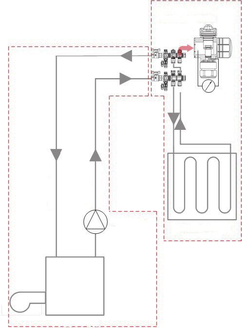
Betriebsanleitung
Heizkreisverteiler
ProCalida VA 1C
Typ:Vario DP
Copyright 2021 AFRISO-EURO-INDEX GmbH. Alle Rechte vorbehalten.
Lindenstraße 20
74363 Güglingen
Telefon +49 7135 102-0
Service +49 7135 102-211
Telefax +49 7135 102-147
info@afriso.com
www.afriso.com
Version: 07.2021.0
ID: 900.000.0953Über diese Betriebsanleitung DE
1 Über diese Betriebsanleitung
Diese Betriebsanleitung beschreibt den Heizkreisverteiler
„ProCalida® VA 1C Vario DP“ mit dynamischer Durchflussregelung (im Fol-
genden auch „Produkt“). Diese Betriebsanleitung ist Teil des Produkts.
• Sie dürfen das Produkt erst benutzen, wenn Sie die Betriebsanleitung
vollständig gelesen und verstanden haben.
• Stellen Sie sicher, dass die Betriebsanleitung für alle Arbeiten an und mit
dem Produkt jederzeit verfügbar ist.
• Geben Sie die Betriebsanleitung und alle zum Produkt gehörenden
Unterlagen an alle Benutzer des Produkts weiter.
• Wenn Sie der Meinung sind, dass die Betriebsanleitung Fehler, Wider-
sprüche oder Unklarheiten enthält, wenden Sie sich vor Benutzung des
Produkts an den Hersteller.
Diese Betriebsanleitung ist urheberrechtlich geschützt und darf ausschließ-
lich im rechtlich zulässigen Rahmen verwendet werden. Änderungen vorbe-
halten.
Für Schäden und Folgeschäden, die durch Nichtbeachtung dieser Betriebs-
anleitung sowie Nichtbeachten der am Einsatzort des Produkts geltenden
Vorschriften, Bestimmungen und Normen entstehen, übernimmt der Herstel-
ler keinerlei Haftung oder Gewährleistung.
ProCalida® VA 1C Vario DP 2Informationen zur Sicherheit DE
2 Informationen zur Sicherheit
2.1 Warnhinweise und Gefahrenklassen
In dieser Betriebsanleitung finden Sie Warnhinweise, die auf potenzielle
Gefahren und Risiken aufmerksam machen. Zusätzlich zu den Anweisungen
in dieser Betriebsanleitung müssen Sie alle am Einsatzort des Produktes
geltenden Bestimmungen, Normen und Sicherheitsvorschriften beachten.
Stellen Sie vor Verwendung des Produktes sicher, dass Ihnen alle Bestim-
mungen, Normen und Sicherheitsvorschriften bekannt sind und dass sie
befolgt werden.
Warnhinweise sind in dieser Betriebsanleitung mit Warnsymbolen und Sig-
nalwörtern gekennzeichnet. Abhängig von der Schwere einer Gefährdungs-
situation werden Warnhinweise in unterschiedliche Gefahrenklassen unter-
teilt.
WARNUNG
WARNUNG macht auf eine möglicherweise gefährliche Situation aufmerk-
sam, die bei Nichtbeachtung einen schweren oder tödlichen Unfall oder
Sachschäden zur Folge haben kann.
HINWEIS
HINWEIS macht auf eine möglicherweise gefährliche Situation aufmerksam, die
bei Nichtbeachtung Sachschäden zur Folge haben kann.
Zusätzlich werden in dieser Betriebsanleitung folgende Symbole verwendet:
Dies ist das allgemeine Warnsymbol. Es weist auf die
Gefahr von Verletzungen und Sachschäden hin. Befolgen
Sie alle im Zusammenhang mit diesem Warnsymbol
beschriebenen Hinweise, um Unfälle mit Todesfolge, Verlet-
zungen und Sachschäden zu vermeiden.
ProCalida® VA 1C Vario DP 3Informationen zur Sicherheit DE
2.2 Bestimmungsgemäße Verwendung
Dieses Produkt eignet sich ausschließlich zum Verteilen von Medien in
Flächenheizungs- und Kühlsystemen in Gebäuden bei Verwendung folgen-
der Medien:
• Heizwasser nach VDI 2035
• Wasser-Glykol-Gemische mit maximal 50 % Beimischung
Eine andere Verwendung ist nicht bestimmungsgemäß und verursacht
Gefahren.
Stellen Sie vor Verwendung des Produkts sicher, dass das Produkt für die
von Ihnen vorgesehene Verwendung geeignet ist. Berücksichtigen Sie dabei
mindestens Folgendes:
• Alle am Einsatzort geltenden Bestimmungen, Normen und Sicherheits-
vorschriften
• Alle für das Produkt spezifizierten Bedingungen und Daten
• Die Bedingungen der von Ihnen vorgesehenen Anwendung
Führen Sie darüber hinaus eine Risikobeurteilung in Bezug auf die konkrete,
von Ihnen vorgesehene Anwendung nach einem anerkannten Verfahren
durch und treffen Sie entsprechend dem Ergebnis alle erforderlichen Sicher-
heitsmaßnahmen. Berücksichtigen Sie dabei auch die möglichen Folgen
eines Einbaus oder einer Integration des Produkts in ein System oder in eine
Anlage.
Führen Sie bei der Verwendung des Produkts alle Arbeiten ausschließlich
unter den in der Betriebsanleitung und auf dem Typenschild spezifizierten
Bedingungen und innerhalb der spezifizierten technischen Daten und in
Übereinstimmung mit allen am Einsatzort geltenden Bestimmungen, Nor-
men und Sicherheitsvorschriften durch.
ProCalida® VA 1C Vario DP 4Informationen zur Sicherheit DE
2.3 Vorhersehbare Fehlanwendung
Das Produkt darf insbesondere in folgenden Fällen und für folgende Zwecke
nicht angewendet werden:
• Verteilung von Trinkwasser
2.4 Qualifikation des Personals
Arbeiten an und mit diesem Produkt dürfen nur von Fachkräften vorgenom-
men werden, die den Inhalt dieser Betriebsanleitung und alle zum Produkt
gehörenden Unterlagen kennen und verstehen.
Die Fachkräfte müssen aufgrund ihrer fachlichen Ausbildung, Kenntnisse
und Erfahrungen in der Lage sein, mögliche Gefährdungen vorherzusehen
und zu erkennen, die durch den Einsatz des Produkts entstehen können.
Den Fachkräften müssen alle geltenden Bestimmungen, Normen und
Sicherheitsvorschriften, die bei Arbeiten an und mit dem Produkt beachtet
werden müssen, bekannt sein.
2.5 Persönliche Schutzausrüstung
Verwenden Sie immer die erforderliche persönliche Schutzausrüstung.
Berücksichtigen Sie bei Arbeiten an und mit dem Produkt auch, dass am Ein-
satzort Gefährdungen auftreten können, die nicht direkt vom Produkt ausge-
hen.
2.6 Veränderungen am Produkt
Führen Sie ausschließlich solche Arbeiten an und mit dem Produkt durch, die
in dieser Betriebsanleitung beschrieben sind. Nehmen Sie keine Verände-
rungen vor, die in dieser Betriebsanleitung nicht beschrieben sind.
ProCalida® VA 1C Vario DP 5Transport und Lagerung DE
3 Transport und Lagerung
Das Produkt kann durch unsachgemäßen Transport und Lagerung beschä-
digt werden.
HINWEIS
UNSACHGEMÄSSE HANDHABUNG
• Stellen Sie sicher, dass während des Transports und der Lagerung des Pro-
dukts die spezifizierten Umgebungsbedingungen eingehalten werden.
• Benutzen Sie für den Transport die Originalverpackung.
• Lagern Sie das Produkt nur in trockener, sauberer Umgebung.
• Stellen Sie sicher, dass das Produkt bei Transport und Lagerung stoßge-
schützt ist.
Nichtbeachtung dieser Anweisungen kann zu Sachschäden führen.
ProCalida® VA 1C Vario DP 6Produktbeschreibung DE
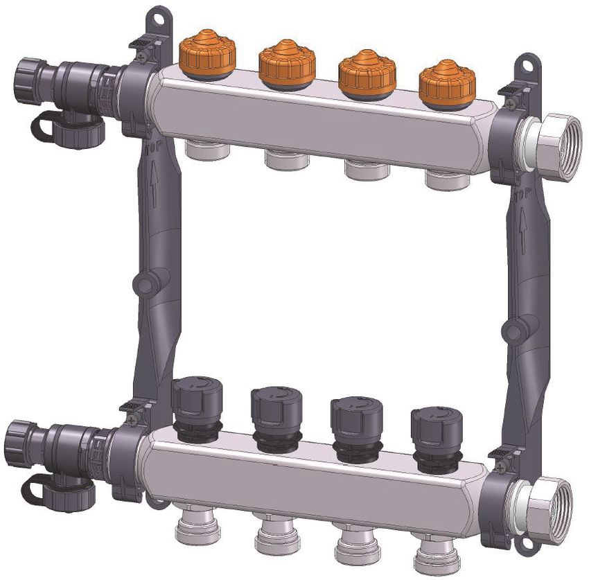
4 Produktbeschreibung
4.1 Übersicht
1 A 2
3
4
5
B
C
D 6
Standardausführung Zubehör (optional)
A. Montagekappe mit Ventileinsatz 1. Stellantrieb
Vario DP
2. Kugelhahn G1
B. Vorlaufventil 3. Kugelhahn mit Thermometer
C. Überwurfmutter G1 oder Außen- 4. Rücklaufventil G1
gewinde G1 (je nach Ausführung)
5. Feinregulierventil G1 für Vorlauf
D. Füll-, Entleer- und Entlüftungs-
hahn 6. Schlauchtülle
ProCalida® VA 1C Vario DP 7Produktbeschreibung DE
4.2 Abmessungen
Heizkreise 2 3 4 5 6 7 8 9 10 11 12
Abstand A 236 286 336 386 436 486 536 586 636 686 736
Abstand B 130 180 230 280 330 380 430 480 530 580 630
A
B
ProCalida® VA 1C Vario DP 8Produktbeschreibung DE
4.3 Technische Daten
Parameter Wert
Hauptanschluss G1 mit Überwurfmutter
Heizkreisanschluss G¾ Eurokonus
Betriebstemperatur und -druck Max. 60 °C bei 6 bar
Max. 90 °C bei 3 bar
Arbeitsbereich 50 bis 700 mbar (Differenzdruck)
Dynamischer Regelbereich 150 bis 700 mbar (Differenzdruck)
Einstellbereich 20 bis 340 l/h
Lieferbare Größen 2 bis 12 Heizkreise
ProCalida® VA 1C Vario DP 9Dimensionierung DE
5 Dimensionierung
HINWEIS
UNSACHGEMÄSSE HANDHABUNG
• Stellen Sie sicher, dass die Umwälzpumpe so dimensioniert ist, dass sie
dem dynamischen Regelbereich entspricht.
• Die erforderliche Pumpenförderhöhe wird anhand des ungünstigsten Heiz-
kreises ermittelt (= größter zu überwindender Widerstand).
• Die dynamischen Ventile Vario DP arbeiten bei Differenzdrücken unter
150 mbar analog zu statischen Ventilen.
Nichtbeachtung dieser Anweisungen kann zu Sachschäden führen.
5.1 Auslegung der Umwälzpumpe
Um den Pumpendruck zu ermitteln, müssen alle Widerstände addiert wer-
den.
Ermittlung des Gesamtwiderstandes:
• Δpges = [ΔpRohrn. + ΔpWz + Δpdyn + ΔpFbh]
ProCalida® VA 1C Vario DP 10Dimensionierung DE
1
A B
2
p1 p2 3
8
7
6 4
5
A. Rohrnetz & Wärmeerzeuger 1. Druck p1
[Δpges = ΔpRohrn. + ΔpWz] 2. HeizkeisverteilerDruck
B. Dynamisches Regelventil & Fußbo- 3. Druck p2
denheizung
[Δpdyn + ΔpFbh] 4. Flächenheiz- und Kühlsystem
5. Wärmeerzeuger
6. Umwälzpumpe
7. Vorlauf
8. Rücklauf
Das System muss so ausgelegt werden, dass über dem Ventil eine Druckdif-
ferenz von mindestens 150 mbar (Δpdyn = p2-p1) herrscht. Dann ist die
Funktion im dynamischen Regelbereich sichergestellt.
ProCalida® VA 1C Vario DP 11Dimensionierung DE
5.2 Berechnung der Wassermenge pro Heizkreis
Beispielrechnung:
• Die errechnete Leistung für den Kreis beträgt 600 Watt.
• Die Temperaturspreizung (VL zu RL) beträgt 7 Kelvin.
ṁ = 73,70 kg/h entspricht 73,70 l/h
• Addieren Sie alle Wassermengen, um den Gesamtförderstrom der
Pumpe zu erhalten.
ProCalida® VA 1C Vario DP 12Montage DE
6 Montage
Das Produkt wird in einem Verteilerschrank oder an der Wand montiert.
Wenn Sie das Produkt in eine bestehende Anlage einbauen, beachten Sie
das Kapitel “Produkt nachrüsten” auf Seite 15.
6.1 Produkt montieren
1. Setzen Sie den Verteiler in den
Halter.
Stellen Sie sicher, dass der obere
Verteiler (A) leicht schräg befes-
A tigt ist und Verteiler (B) gerade.
B
ProCalida® VA 1C Vario DP 13Montage DE
2. Klappen Sie den Bügel nach oben
und rasten Sie ihn ein (klick).
3. Fixieren Sie den Bügel mit einer
Schraube.
ProCalida® VA 1C Vario DP 14Montage DE
6.2 Produkt nachrüsten
WARNUNG
HEISSE FLÜSSIGKEIT
Wasser in Heizungsanlagen steht unter einem hohen Druck und kann Tempe-
raturen bis über 100 °C erreichen.
• Stellen Sie sicher, dass das Heizwasser abgekühlt ist, bevor Sie die Anlage
öffnen und das Produkt montieren.
• Stellen Sie sicher, dass die Anlage drucklos und entleert ist, bevor Sie die
Anlage öffnen und das Produkt montieren.
Nichtbeachtung dieser Anweisung kann zu Tod, schweren Verletzungen
oder Sachschäden führen.
Stellen Sie sicher, dass die Flüssigkeit in der Anlage mit dem Einsatzbe-
reich des Produkts verträglich ist.
Wenn die Anlage abgekühlt und drucklos ist, können Sie das Produkt mon-
tieren.
1. Entleeren Sie die Anlage.
2. Spülen Sie die Leitungen der Anlage.
3. Montieren Sie das Produkt wie in Kapitel "Produkt montieren" beschrie-
ben.
ProCalida® VA 1C Vario DP 15Inbetriebnahme DE
7 Inbetriebnahme
7.1 Anlage spülen, befüllen und entlüften
A B
H
G
C
F
E
Das Produkt darf nur über den Rücklauf befüllt werden.
Die Anlage muss während und nach dem Befüllen entlüftet werden.
1. Schließen Sie einen Schlauch an den Schlauchanschluss des
Füllhahns (G) an.
2. Drehen Sie den Schlauchanschluss des Entlüftungshahns (E) um 180°,
so dass der nach oben zeigt.
3. Schließen Sie einen Schlauch an den Schlauchanschluss des
ProCalida® VA 1C Vario DP 16Inbetriebnahme DE
Entlüftungshahns (E) an.
4. Öffnen Sie das Handrad (F und H) am Füll- und Entlüftungshahn.
5. Entfernen Sie alle Montagekappen (B) der Rücklaufventile Vario DP.
6. Stellen Sie alle Rücklaufventile (A) auf den Skalenwert 8.
7. Schließen Sie alle Vorlaufventile (C).
8. Öffnen Sie das Vorlaufventil des zu spülenden Heizkreises minimal.
9. Spülen und befüllen Sie den Heizkreis mit maximal 2 bar.
10.Öffnen Sie dann das Vorlaufventil vollständig.
11. Schließen Sie das Vorlaufventil des befüllten Heizkreises.
- Das Rücklaufventil bleibt offen.
12.Wiederholen sie die Schritte 8-11 für jeden weiteren Heizkreis.
13.Schließen Sie das Handrad (F und H) am Füll- und Entlüftungshahn.
14.Stellen Sie die Umwälzpumpe auf Konstantdruck ein (benötigte Gesamt-
förderhöhe beachten).
15.Stellen Sie die Rücklaufventile anhand des Diagramms (siehe Seite "Dia-
gramm") ein.
16.Montieren und schließen Sie die Stellantriebe oder drehen Sie die Mon-
tagekappen (B) auf die Rücklaufventile bis sie geschlossen sind.
17.Führen Sie eine Dichtheitsprüfung in Form einer Druckprüfung durch.
7.2 Dichtheitsprüfung
Stellen Sie sicher, dass der Differenzdruck zwischen Vor- und Rücklauf
maximal 1 bar beträgt.
Wenn beispielsweise die Rücklaufventile geschlossen sind und der Diffe-
renzdruck ist größer als 1 bar, müssen Sie den Differenzdruck durch Öffnen
der Vorlaufventile ausgleichen.
Öffnen Sie alle Ventile, so dass in der Anlage überall der gleiche System-
druck herrscht.
Der maximal zulässige Prüfdruck beträgt bei Wasser 6 bar, bei Luft
3 bar.
ProCalida® VA 1C Vario DP 17Wartung DE
8 Wartung
Das Produkt ist wartungsfrei.
9 Störungsbeseitigung
Störungen dürfen nur durch den Hersteller oder Fachkräfte behoben werden.
10 Außerbetriebnahme und Entsorgung
Entsorgen Sie das Produkt nach den geltenden Bestimmungen, Normen und
Sicherheitsvorschriften.
1. Demontieren Sie das Produkt (siehe Kapitel "Montage" in umgekehrter
Reihenfolge).
2. Entsorgen Sie das Produkt.
11 Rücksendung
Vor einer Rücksendung Ihres Produkts müssen Sie sich mit uns in Verbin-
dung setzen (service@afriso.de).
12 Gewährleistung
Informationen zur Gewährleistung finden Sie in unseren Allgemeinen
Geschäftsbedingungen im Internet unter www.afriso.com oder in Ihrem Kauf-
vertrag.
13 Ersatzteile und Zubehör
Produkt
Artikelbezeichnung Art.-Nr. Abbildung
Heizkreisverteiler 86422
„ProCalida® VA 1C Vario DP“ 86423
mit Überwurfmutter G1 86424
86425
86426
86427
86428
86429
86430
86431
86432
ProCalida® VA 1C Vario DP 1814
Voreinstellung
Ventil:
1
1•
1••
1•••
2
2•
2••
2•••
3
3•
3••
3•••
4
4•
4••
4•••
5
5•
5••
5•••
6
6•
6••
6•••
7
7•
7••
7•••
8
Wassermenge in l/h:
Differenzdruck:
20 20 25 25 35 40 45 55 65 80 90 100 115 135 145 160 170 185 200 215 230 245 260 275 290 300 315 330 340
bis 70 kPa
Anhang
14.1 Diagramm
Anhang
ProCalida® VA 1C Vario DP
19
DEOperating
instructions
Heating circuit manifold
ProCalida VA 1C
Type: Vario DP
Copyright 2021 AFRISO-EURO-INDEX GmbH. All rights reserved.
Lindenstraße 20
74363 Güglingen
Telephone +49 7135 102-0
Service +49 7135 102-211
Telefax +49 7135 102-147
info@afriso.com
www.afriso.com
Version: 07.2021.0
ID: 900.000.0953About these operating instructions EN
1 About these operating instructions
These operating instructions describe the heating circuit manifold
"ProCalida® VA 1C Vario DP" with dynamic flow control (also referred to as
"product" in these operating instructions). These operating instructions are
part of the product.
• You may only use the product if you have fully read and understood these
operating instructions.
• Verify that these operating instructions are always accessible for any type
of work performed on or with the product.
• Pass these operating instructions as well as all other product-related doc-
uments on to all owners of the product.
• If you feel that these operating instructions contain errors, inconsisten-
cies, ambiguities or other issues, contact the manufacturer prior to using
the product.
These operating instructions are protected by copyright and may only be
used as provided for by the corresponding copyright legislation. We reserve
the right to modifications.
The manufacturer shall not be liable in any form whatsoever for direct or con-
sequential damage resulting from failure to observe these operating instruc-
tions or from failure to comply with directives, regulations and standards and
any other statutory requirements applicable at the installation site of the prod-
uct.
ProCalida® VA 1C Vario DP 2Information on safety EN
2 Information on safety
2.1 Safety messages and hazard categories
These operating instructions contain safety messages to alert you to poten-
tial hazards and risks. In addition to the instructions provided in these oper-
ating instructions, you must comply with all directives, standards and safety
regulations applicable at the installation site of the product. Verify that you are
familiar with all directives, standards and safety regulations and ensure com-
pliance with them prior to using the product.
Safety messages in these operating instructions are highlighted with warning
symbols and warning words. Depending on the severity of a hazard, the
safety messages are classified according to different hazard categories.
WARNING
WARNING indicates a potentially hazardous situation, which, if not avoided,
can result in serious injury or equipment damage.
NOTICE
NOTICE indicates a hazardous situation, which, if not avoided, can result in
equipment damage.
In addition, the following symbols are used in these operating instructions:
This is the general safety alert symbol. It alerts to injury haz-
ards or equipment damage. Comply with all safety instruc-
tions in conjunction with this symbol to help avoid possible
death, injury or equipment damage.
ProCalida® VA 1C Vario DP 3Information on safety EN
2.2 Intended use
This product may only be used for the distribution of media in panel heating
system and refrigeration systems in buildings in conjunction with the follow-
ing media:
• Heating water as per VDI 2035
• Water/glycol mixtures with a maximum admixture of 50 %
Any use other than the application explicitly permitted in these operating
instructions is not permitted and causes hazards.
Verify that the product is suitable for the application planned by you prior to
using the product. In doing so, take into account at least the following:
• All directives, standards and safety regulations applicable at the installa-
tion site of the product
• All conditions and data specified for the product
• The conditions of the planned application
In addition, perform a risk assessment in view of the planned application,
according to an approved risk assessment method, and implement the
appropriate safety measures, based on the results of the risk assessment.
Take into account the consequences of installing or integrating the product
into a system or a plant.
When using the product, perform all work and all other activities in conjunc-
tion with the product in compliance with the conditions specified in the oper-
ating instructions and on the nameplate, as well as with all directives, stand-
ards and safety regulations applicable at the installation site of the product.
ProCalida® VA 1C Vario DP 4Information on safety EN
2.3 Predictable incorrect application
The product must never be used in the following cases and for the following
purposes:
• Distribution of drinking water
2.4 Qualification of personnel
Only appropriately trained persons who are familiar with and understand the
contents of these operating instructions and all other pertinent product docu-
mentation are authorized to work on and with this product.
These persons must have sufficient technical training, knowledge and expe-
rience and be able to foresee and detect potential hazards that may be
caused by using the product.
All persons working on and with the product must be fully familiar with all
directives, standards and safety regulations that must be observed for per-
forming such work.
2.5 Personal protective equipment
Always wear the required personal protective equipment. When performing
work on and with the product, take into account that hazards may be present
at the installation site which do not directly result from the product itself.
2.6 Modifications to the product
Only perform work on and with the product which is explicitly described in
these operating instructions. Do not make any modifications to the product
which are not described in these operating instructions.
ProCalida® VA 1C Vario DP 5Transport and storage EN
3 Transport and storage
The product may be damaged as a result of improper transport or storage.
NOTICE
INCORRECT HANDLING
• Verify compliance with the specified ambient conditions during transport or
storage of the product.
• Use the original packaging when transporting the product.
• Store the product in a clean and dry environment.
• Verify that the product is protected against shocks and impact during trans-
port and storage.
Failure to follow these instructions can result in equipment damage.
ProCalida® VA 1C Vario DP 6Product description EN
4 Product description
4.1 Overview
1 A 2
3
4
5
B
C
D 6
Standard version Accessories (optional)
A. Mounting cap with valve insert 1. Actuator
Vario DP
2. Ball valve G1
B. Flow valve 3. Ball valve with thermometer
C. Union nut G1 or male thread G1 4. Return valve G1
(depending on version)
5. Fine adjustment valve G1 for flow
D. Filling, drain and vent valve
6. Hose connector
ProCalida® VA 1C Vario DP 7Product description EN
4.2 Dimensions
Heating 2 3 4 5 6 7 8 9 10 11 12
circuits
Distance A 236 286 336 386 436 486 536 586 636 686 736
Distance B 130 180 230 280 330 380 430 480 530 580 630
A
B
ProCalida® VA 1C Vario DP 8Product description EN
4.3 Technical data
Parameter Value
Main connection G1 with union nut
Heating circuit connection G¾ eurocone
Operating temperature and pres- Max. 60 °C at 6 bar
sure Max. 90 °C at 3 bar
Operating range 50 to 700 mbar (differential pressure)
Dynamic control range 150 to 700 mbar (differential pressure)
Adjustment range 20 to 340 l/h
Available sizes 2 to 12 heating circuits
ProCalida® VA 1C Vario DP 9Rating EN
5 Rating
NOTICE
INCORRECT HANDLING
• Verify that the circulation pump is rated in such a way that it corresponds to
the dynamic control range.
• The required pumping head is determined on the basis of the most unfavour-
able heating circuit (= greatest resistance to overcome).
• The dynamic valves Vario DP operate at differential pressures below
150 mbar analogously to static valves.
Failure to follow these instructions can result in equipment damage.
5.1 Rating of the circulation pump
To determine the pump pressure, all resistances must be added.
Determination of the total resistance:
• Δptot = [ΔpPiping + ΔpHg + Δpdyn + ΔpUfh]
ProCalida® VA 1C Vario DP 10Rating EN
1
A B
2
p1 p2 3
8
7
6 4
5
A. Piping & heat generator 1. Pressure p1
[Δptot = ΔpPiping + ΔpHg] 2. Heating circuit manifold pressure
B. Dynamic control valve & under- 3. Pressure p2
floor heating system
[Δpdyn + ΔpUfh] 4. Panel heating and cooling system
5. Heat generator
6. Circulation pump
7. Flow
8. Return
The system must be rated in such a way that there is a pressure difference
of at least 150 mbar (Δpdyn = p2-p1) across the valve. Then, operation in the
dynamic control range is ensured.
ProCalida® VA 1C Vario DP 11Rating EN
5.2 Calculation of the water volume per heating circuit
Example calculation:
• The power determined for the circuit amounts to 600 W.
• The temperature spread (flow to return) amounts to 7 Kelvin.
ṁ = 73.70 kg/h corresponds to 73.70 l/h
• Add all water volumes to determine the total flow of the pump.
ProCalida® VA 1C Vario DP 12Mounting EN
6 Mounting
The product is mounted in a manifold cabinet or to the wall.
If you install the product in an existing system, observe the information in
chapter “Retrofitting the product” on page 15.
6.1 Mounting the product
1. Place the manifold into the
bracket.
Verify that the upper manifold (A)
is slightly tilted and manifold (B) is
A straight.
B
ProCalida® VA 1C Vario DP 13Mounting EN
2. Click-fit the clip towards the top
(must snap in).
3. Fixate the clip with a screw.
ProCalida® VA 1C Vario DP 14Mounting EN
6.2 Retrofitting the product
WARNING
HOT LIQUID
Water in heating systems is under high pressure and can have temperatures of
more than 100 °C.
• Verify that the heating water has cooled down before opening the system
and mounting the product.
• Verify that the system has been unpressurised and drained before mounting
the product.
Failure to follow these instructions can result in death, serious injury or
equipment damage.
Verify that the liquid in the system and the application area of the product
are compatible.
When the system has cooled down and unpressurised, you can mount the
product.
1. Drain the system.
2. Flush the lines of the system.
3. Mount the product as described in chapter "Mounting the product".
ProCalida® VA 1C Vario DP 15Commissioning EN
7 Commissioning
7.1 Flushing, filling and venting the system
A B
H
G
C
F
E
The product must not be filled via the return.
The system must be vented during and after filling.
1. Connect a hose to the hose connection of the filling valve KFE (G).
2. Rotate the hose connection of the vent valve (E) by 180° so that it points
upwards.
3. Connect a hose the the hose connection of the vent valve (E).
4. Open the hand wheel (F and H) at the filling and vent valve.
ProCalida® VA 1C Vario DP 16Commissioning EN
5. Remove all mounting caps (B) of the return valves Vario DP.
6. Set all return valves (A) to the scale value 8.
7. Close all flow valves (C).
8. Slightly open the flow valve of the heating circuit to be flushed.
9. Flush and fill the heating circuit with a maximum of 2 bar.
10.Then open the flow valve fully.
11. Close the flow valve of the filled heating circuit.
- The return valve remains open.
12.Repeat steps 8 to 11 for each additional heating circuit.
13.Close the hand wheel (F and H) at the filling and vent valve.
14.Set the circulation pump to constant pressure (note required total head).
15.Adjust the return valves according to the diagram (refer to page "Chart").
16.Mount and close the actuators or turn the mounting caps (B) onto the
return valve until they are closed.
17.Perform a tightness test in the form of a pressure test.
7.2 Tightness test
Verify that the differential pressure between flow and return amounts to a
maximum of 1 bar.
If, for example, the return valves are closed and the differential pressure is
greater than 1 bar, you must adjust the differential pressure by opening the
flow valves.
Open all valves so that the system pressure is the same in the entire system.
The maximum permissible test pressure amounts to 6 bar for water and
to 3 bar for air.
ProCalida® VA 1C Vario DP 17Maintenance EN
8 Maintenance
The product is maintenance-free.
9 Troubleshooting
Malfunctions may only be repaired by the manufacturer or by qualified per-
sons.
10 Decommissioning, disposal
Dispose of the product in compliance with all applicable directives, standards
and safety regulations.
1. Dismount the product (see chapter "Mounting", reverse sequence of
steps).
2. Dispose of the product.
11 Returning the device
Get in touch with us before returning your product (service@afriso.de).
12 Warranty
See our terms and conditions at www.afriso.com or your purchase contract
for information on warranty.
13 Spare parts and accessories
Product
Product designation Part no. Figure
Heating circuit manifold 86422
"ProCalida® VA 1C Vario DP" 86423
with union nut G1 86424
86425
86426
86427
86428
86429
86430
86431
86432
ProCalida® VA 1C Vario DP 1814
Voreinstellung
Ventil:
1
1•
1••
1•••
2
2•
2••
2•••
3
3•
3••
3•••
4
4•
4••
4•••
5
5•
5••
5•••
6
6•
6••
6•••
7
7•
7••
7•••
8
Wassermenge in l/h:
Differenzdruck:
20 20 25 25 35 40 45 55 65 80 90 100 115 135 145 160 170 185 200 215 230 245 260 275 290 300 315 330 340
bis 70 kPa
14.1 Chart
Appendix
Appendix
ProCalida® VA 1C Vario DP
19
ENIstruzioni per l’uso
Modulo di distribuzione per riscaldamenti
ProCalida VA 1C
Tipo: Vario DP
Copyright 2021 AFRISO-EURO-INDEX GmbH. Tutti i diritti sono riservati.
Lindenstraße 20
74363 Güglingen
Telefono +49 7135 102-0
Servizio di assistenza +49 7135 102-211
Telefax +49 7135 102-147
info@afriso.com
www.afriso.com
Versione: 07.2021.0
ID: 900.000.0953Su queste Istruzioni per l'uso IT
1 Su queste Istruzioni per l'uso
Queste Istruzioni per l'uso descrivono il modulo di distribuzione per riscalda-
menti "ProCalida® VA 1C Vario DP" con regolazione dinamica del flusso
(nel prosieguo anche "prodotto"). Le presenti Istruzioni per lʼuso costitui-
scono parte del prodotto.
• L'utilizzo del prodotto è permesso soltanto dopo aver letto e capito com-
pletamente le Istruzioni per l'uso.
• Assicurate che le Istruzioni per l'uso siano disponibili per ogni intervento
sul prodotto e ogni lavoro con il prodotto.
• Consegnate le Istruzioni per l'uso e tutta la documentazione relativa al
prodotto a tutti gli utilizzatori del prodotto.
• Se siete dell'avviso che le Istruzioni per l'uso contengano errori, contrad-
dizioni o non siano chiare, rivolgetevi al produttore prima di utilizzare il
prodotto.
Queste Istruzioni per l'uso sono protette da diritto d'autore e il loro utilizzo è
riservato al contesto legalmente ammesso. Con riserva di modifiche.
Lʼazienda produttrice declina ogni responsabilità e garanzia per danni diretti
e conseguenti che risultano dalla mancata osservanza delle Istruzioni per
l'uso nonché delle disposizioni, prescrizioni e norme valide sul posto
d'impiego del prodotto.
ProCalida® VA 1C Vario DP 2Informazioni sulla sicurezza IT
2 Informazioni sulla sicurezza
2.1 Avvertenze e classi di pericolosità
Queste Istruzioni per l'uso contengono avvertenze che richiamano l'atten-
zione a pericoli e rischi. In aggiunta alle avvertenze riportate nelle Istruzioni
per l'uso sono da rispettare tutte le disposizioni, prescrizioni e norme di sicu-
rezza vigenti sul posto d'impiego del prodotto. Prima di utilizzare il prodotto,
assicurare di conoscere tutte le disposizioni, prescrizioni e norme di sicu-
rezza vigenti e di averle rispettate.
Le avvertenze in queste Istruzioni per l'uso sono contrassegnate da simboli
di avvertimento e parole di avvertenza. A dipendere dalla serietà della situa-
zione di pericolo le avvertenze sono suddivise in varie classi di pericolosità.
AVVERTIMENTO
L'AVVERTIMENTO richiama l'attenzione a una situazione potenzialmente
pericolosa, che può causare un incidente grave o mortale o danni materiali
in caso di non osservanza.
AVVISO
L'AVVISO richiama l'attenzione a una situazione potenzialmente pericolosa,
che può causare danni in caso di non osservanza.
In aggiunta, in queste Istruzioni per l'uso vengono utilizzati i seguenti simboli:
Questo è il simbolo di avvertimento generico. Avverte del
pericolo di lesioni fisiche o danni materiali. Rispettate sem-
pre le indicazioni corredate del simbolo di avvertimento per
evitare incidenti con conseguenze anche fatali, lesioni fisi-
che e danni materiali.
ProCalida® VA 1C Vario DP 3Informazioni sulla sicurezza IT
2.2 Uso conforme
Questo prodotto è idoneo esclusivamente alla distribuzione di fluidi in
impianti di riscaldamento a pavimento o sistemi di refrigerazione in edifici che
utilizzano i seguenti fluidi:
• acqua di riscaldamento secondo VDI 2035
• miscele di acqua-glicole con max. 50 % di additivo
Ogni altro utilizzo è da considerarsi non conforme e causa pericoli.
Prima di utilizzare il prodotto, assicurare che sia adatto allo scopo previsto.
Così facendo, tenete conto almeno dei seguenti punti:
• tutte le disposizioni, norme e prescrizioni di sicurezza vigenti sul posto
d'impiego
• tutte le condizioni e i dati specificati per il prodotto
• le condizioni dell'applicazione da voi prevista.
Eseguite inoltre una valutazione dei rischi relativa all'applicazione concreta
da voi prevista con in base a un procedimento riconosciuto e provvedete alle
necessarie misure di sicurezza in base al risultato. Tenete conto anche delle
possibili conseguenze dell'installazione o integrazione del prodotto in un
sistema o impianto.
Quando utilizzate il prodotto, eseguite tutti i lavori esclusivamente nel rispetto
delle condizioni specificate nelle Istruzioni per l'uso e sulla targhetta conosci-
tiva, nell'ambito dei dati tecnici specificati e in osservanza di tutte le disposi-
zioni norme e prescrizioni di sicurezza vigenti sul luogo d'impiego.
ProCalida® VA 1C Vario DP 4Informazioni sulla sicurezza IT
2.3 Uso improprio prevedibile
Il prodotto non può essere utilizzato in particolar modo nei seguenti casi e per
i seguenti scopi:
• distribuzione di acqua potabile
2.4 Qualifica del personale
I lavori con e a questo prodotto sono prerogativa di personale specializzato,
che conosce ed ha capito i contenuti di queste Istruzioni per l'uso e tutta la
documentazione che fa parte del prodotto.
In base alla loro formazione professionale, le loro conoscenze ed espe-
rienze, il personale specializzato deve essere in grado di prevedere e ricono-
scere possibili rischi e causati dall'utilizzo del prodotto.
Il personale specializzato deve essere a conoscenza di tutte le disposizioni,
norme e prescrizioni di sicurezza vigenti che si riferiscono ai lavori con e al
prodotto.
2.5 Dispositivi di protezione individuale
L'utilizzo dei necessari dispositivi di protezione individuale è obbligatorio.
Durante il lavoro con e al prodotto, tenete conto anche che sul luogo
d'impiego possono nascere pericolo che non derivano direttamente dal pro-
dotto.
2.6 Modifiche del prodotto
Eseguite esclusivamente i lavori con e al prodotto descritti nelle Istruzioni per
l'uso. Non apportate modifiche al prodotto che non sono descritte nelle Istru-
zioni per l'uso.
ProCalida® VA 1C Vario DP 5Trasporto e magazzinaggio IT
3 Trasporto e magazzinaggio
I prodotto può riportare danni da trasporto e magazzinaggio non adeguato.
AVVISO
UTILIZZO IMPROPRIO
• Assicurare che le condizioni ambientali specificate per il trasporto e il magaz-
zinaggio siano rispettate.
• Per il trasporto, utilizzate l'imballaggio originale.
• Immagazzinate il prodotto solo in ambiente asciutto e pulito.
• Assicurare che il prodotto sia prodotto contro urti durante il trasporto e il
magazzinaggio.
La mancata osservanza di queste indicazioni può causare danni materiali.
ProCalida® VA 1C Vario DP 6Descrizione del prodotto IT
4 Descrizione del prodotto
4.1 Riassuntivo
1 A 2
3
4
5
B
C
D 6
Versione standard Accessori (opzionali)
A. Coperchio di montaggio con 1. Attuatore
inserto valvola Vario DP
2. Rubinetto a sfera G1
B. Valvola di mandata 3. Valvola a sfera con termometro
C. Dado per raccordi G1 o filettatura 4. Valvola ritorno G1
esterna G1 (a seconda dell'ese-
cuzione) 5. Valvola di taratura G1 per man-
data
D. Rubinetto di riempimento, svuota-
mento e sfiato 6. Boccola del tubo flessibile
ProCalida® VA 1C Vario DP 7Descrizione del prodotto IT
4.2 Dimensioni
Circuiti di 2 3 4 5 6 7 8 9 10 11 12
riscalda-
mento
Distanza A 236 286 336 386 436 486 536 586 636 686 736
Distanza B 130 180 230 280 330 380 430 480 530 580 630
A
B
ProCalida® VA 1C Vario DP 8Descrizione del prodotto IT
4.3 Specifiche tecniche
Parametri Valore
Collegamento circuito principale G1 con dado per raccordi
Collegamento circuito di riscalda- G¾ Eurokonus
mento
Temperatura e pressione dʼeser- max. 60 °C a 6 bar
cizio max. 90 °C a 3 bar
Ambito di lavoro da 50 a 700 mbar (pressione differen-
ziale)
Ambito di regolazione dinamico da 150 a 700 mbar (pressione differen-
ziale)
Ambito di impostazione da 20 a 340 l/h
Grandezze disponibili da 2 a 12 circuiti di riscaldamento
ProCalida® VA 1C Vario DP 9Dimensionamento IT
5 Dimensionamento
AVVISO
UTILIZZO IMPROPRIO
• Assicuratevi che la pompa di ricircolo sia dimensionata in modo da corri-
spondere all'ambito di regolazione dinamico.
• La prevalenza necessaria viene determinata in base dal circuito di riscalda-
mento meno favorevole (= con la resistenza maggiore da superare).
• Per pressioni differenziali sotto 150 mbar le valvole dinamiche Vario DP fun-
zionano analogamente a valvole statiche.
La mancata osservanza di queste indicazioni può causare danni materiali.
5.1 Dimensionamento della pompa di ricircolo
Per determinare la pressione della pompa si devono sommare tutte le resi-
stenze.
Determinazione della resistenza complessiva:
• Δpges = [ΔpRohrn. + ΔpWz + Δpdyn + ΔpFbh]
ProCalida® VA 1C Vario DP 10Dimensionamento IT
1
A B
2
p1 p2 3
8
7
4
6
5
A. Rete tubiera & generatore di 1. Pressione p1
calore
2. Pressione distributore circuiti di
[Δpges = ΔpRohrn. + ΔpWz] riscaldamento
B. Valvola di regolazione dinamica
3. Pressione p2
& riscaldamento a pavimento
[Δpdyn + ΔpFbh] 4. Sistema riscaldamento superfici e
raffreddamento
5. Generatore di calore
6. Pompa di ricircolo
7. Mandata
8. Ritorno
Il sistema deve essere dimensionato in modo che sulla valvola agisce una
pressione differenziale di almeno 150 mbar (Δpdyn = p2-p1). Così è assicu-
rato il funzionamento nell'ambito di regolazione dinamico.
ProCalida® VA 1C Vario DP 11Dimensionamento IT
5.2 Calcolo della quantità d'acqua per circuito di riscaldamento
Calcolo esemplare:
• La prestazione calcolata per il circuito è pari a 600 watt.
• La differenza di temperatura (mandata risp. ritorno) è pari a 7 kelvin.
ṁ = 73,70 kg/h corrisponde a 73,70 l/h
• Sommare tutti i volumi d'acqua per ottenere il flusso totale della pompa.
ProCalida® VA 1C Vario DP 12Montaggio IT
6 Montaggio
Il prodotto viene montato in un armadio di distribuzione o a muro oppure
direttamente su parete.
Dovendo montare il prodotto in un impianto esistente, tenere conto del capi-
tolo “Ampliamento del prodotto” a pagina 15.
6.1 Montaggio dell’apparecchio
1. Inserite il distributore sul sup-
porto.
Assicuratevi che il distributore
superiore (A) sia posizionato leg-
A germente inclinato e il distributore
(B) sia diritto.
B
ProCalida® VA 1C Vario DP 13Montaggio IT
2. Ribaltate l'archetto verso l'alto per
farlo incastrare (clic).
3. Fissate l'archetto con una vite.
ProCalida® VA 1C Vario DP 14Montaggio IT
6.2 Ampliamento del prodotto
AVVERTIMENTO
LIQUIDI SCOTTANTI
Lʼacqua negli impianti di riscaldamento è in forte pressione e può raggiungere
temperature di oltre 100 °C.
• Assicuratevi che l'acqua di riscaldamento si sia raffreddata prima di aprire
l'impianto e montare il prodotto.
• Assicuratevi che l'acqua di riscaldamento si sia raffreddata prima di aprire
l'impianto e montare il prodotto.
La mancata osservanza di queste indicazioni può causare lesioni mortali,
gravi o danni materiali.
Assicurare che il liquido contenuto nell'impianto sia compatibile con
l'ambito di impiego del prodotto.
Il prodotto si può montare quando l'impianto si è raffreddato e non è più in
pressione.
1. Svuotare l'impianto.
2. Sciacquare le tubature.
3. Montare il prodotto come descritto al Capitolo "Montaggio dellʼapparec-
chio".
ProCalida® VA 1C Vario DP 15Messa in funzione IT
7 Messa in funzione
7.1 Riempire, sciacquare, sfiatare l’impianto.
A B
H
G
C
F
E
Il prodotto si può riempire solo tramite il ritorno.
L'impianto dev'essere sfiatato durante e dopo il riempimento.
1. Collegare un tubo al raccordo tubiero del rubinetto di riempimento e
scarico (G).
2. Ruotare di 180° il raccordo tubiero del rubinetto di sfiato (E) in modo che
sia rivolto verso l'alto.
3. Collegare un tubo (D) al raccordo tubiero del rubinetto di sfiato (E).
ProCalida® VA 1C Vario DP 16Messa in funzione IT
4. Aprire la manopola (F e H) su rubinetto di riempimento e sfiato.
5. Rimuovere tutte le cappe di montaggio (B) dalle valvole di ritorno Vario
DP.
6. Impostare tutte le valvole di ritorno (A) al valore di scala 8.
7. Chiudere tutte le valvole di mandata (C).
8. Aprire di pochissimo la valvola di mandata del circuito di riscaldamento da
sciacquare.
9. Sciacquare e riempire il circuito di riscaldamento con max. 2 bar.
10.Quindi aprire completamente la valvola di mandata.
11. Chiudere la valvola di mandata del circuito riempito.
- La valvola di ritorno resta aperta.
12.Ripetere i passi da 8 a 11 per tutti gli altri circuiti di riscaldamento.
13.Richiudere la manopola (F e H) sul rubinetto di riempimento e sfiato.
14.Impostare una pressione costante sulla pompa di ricircolo (tenere conto
della prevalenza necessaria).
15.Impostare le valvole di ritorno in base al diagramma (cf. pag. "Dia-
gramma").
16.Montare e chiudere gli attuatori o ruotare le cappe di montaggio (B) sulle
valvole di ritorno finché non sono chiuse.
17.Eseguire una prova di tenuta in forma di prova di pressione.
7.2 Prova di tenuta
Assicuratevi che la pressione differenziale tra mandata e ritorno sia max
1 bar.
Se, ad esempio, le valvole di ritorno sono chiuse e la pressione differenziale
è superiore a 1 bar, la pressione differenziale deve essere corretta mediante
l'apertura delle valvole di mandata.
Aprire tutte le valvole in modo che nell'intero impianto ci sia la stessa pres-
sione di sistema.
La pressione di prova max per acqua è pari a 6 bar, per aria a 3 bar.
ProCalida® VA 1C Vario DP 17Manutenzione IT
8 Manutenzione
Il prodotto non richiede manutenzione.
9 Riparazione guasti
I guasti devono essere riparati dal fornitore o da personale specializzato.
10 Smontaggio e smaltimento
Smaltire il prodotto in osservanza delle disposizioni, norme e prescrizioni di
sicurezza vigenti.
1. Smontare il prodotto (si veda il Cap. "Montaggio", in ordine inverso).
2. Smaltire il prodotto.
11 Rispedizione al fornitore
Prima di rispedire il prodotto, mettetevi in contatto con noi
(service@afriso.de).
12 Garanzia
Le informazioni sulla garanzia sono riportate nelle condizioni di contratto
generali in internet sul sito www.afriso.com o nel vostro contratto d'acquisto.
13 Ricambi e accessori
Prodotto
Nome articolo Art. N° Figura
Modulo di distribuzione per 86422
riscaldamenti 86423
"ProCalida® VA 1C Vario DP" 86424
con dado per raccordi G1 86425
86426
86427
86428
86429
86430
86431
86432
ProCalida® VA 1C Vario DP 1814
Voreinstellung
Ventil:
1
1•
1••
1•••
2
2•
2••
2•••
3
3•
3••
3•••
4
4•
4••
4•••
5
5•
5••
5•••
6
6•
6••
6•••
7
7•
7••
7•••
8
Wassermenge in l/h:
Differenzdruck:
20 20 25 25 35 40 45 55 65 80 90 100 115 135 145 160 170 185 200 215 230 245 260 275 290 300 315 330 340
bis 70 kPa
14.1 Diagramma
Appendice
Appendice
ProCalida® VA 1C Vario DP
19
ITSie können auch lesen