Betriebsanleitung Operating instructions Notice technique
←
→
Transkription von Seiteninhalten
Wenn Ihr Browser die Seite nicht korrekt rendert, bitte, lesen Sie den Inhalt der Seite unten
Betriebsanleitung
Operating instructions
Notice technique

                                                               Heizölfilter
                                                              Fuel oil filter
                                                                Filtre fuel

                     Copyright 2021 AFRISO-EURO-INDEX GmbH. Alle Rechte vorbehalten.

                                                                         Lindenstraße 20
                                                                        74363 Güglingen
                                                MVV TB
                                                                 Telefon +49 7135 102-0
                                                C2.15.23
                                               EN 12514-2      Service +49 7135 102-211
                                                               Telefax +49 7135 102-147
                                                                         info@afriso.com
                     in Verbindung mit einem                              www.afriso.com
                     PA-Schlauch 4 x 1 mm
Version: 11.2021.0
ID: 900.000.0062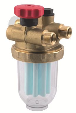
Betriebsanleitung

Heizölfilter
                                                   Einstrangfilter V, R
                                                    Zweistrangfilter Z

                     Copyright 2021 AFRISO-EURO-INDEX GmbH. Alle Rechte vorbehalten.

                                                                         Lindenstraße 20
                                                                        74363 Güglingen
                                                                 Telefon +49 7135 102-0
                                               MVV TB
                                               C 2.15.23       Service +49 7135 102-211
                                              EN 12514-2       Telefax +49 7135 102-147
                                                                         info@afriso.com
                                                                          www.afriso.com
Version: 11.2021.0
ID: 900.000.0062
Über diese Betriebsanleitung                                    DE

1   Über diese Betriebsanleitung
    Diese Betriebsanleitung beschreibt Heizölfilter (im Folgenden auch „Pro-
    dukt“). Diese Betriebsanleitung ist Teil des Produkts.
    •   Sie dürfen das Produkt erst benutzen, wenn Sie die Betriebsanleitung
        vollständig gelesen und verstanden haben.
    •   Stellen Sie sicher, dass die Betriebsanleitung für alle Arbeiten an und mit
        dem Produkt jederzeit verfügbar ist.
    •   Geben Sie die Betriebsanleitung und alle zum Produkt gehörenden
        Unterlagen an alle Benutzer des Produkts weiter.
    •   Wenn Sie der Meinung sind, dass die Betriebsanleitung Fehler, Wider-
        sprüche oder Unklarheiten enthält, wenden Sie sich vor Benutzung des
        Produkts an den Hersteller.
    Diese Betriebsanleitung ist urheberrechtlich geschützt und darf ausschließ-
    lich im rechtlich zulässigen Rahmen verwendet werden. Änderungen vorbe-
    halten.
    Für Schäden und Folgeschäden, die durch Nichtbeachtung dieser Betriebs-
    anleitung sowie Nichtbeachten der am Einsatzort des Produkts geltenden
    Vorschriften, Bestimmungen und Normen entstehen, übernimmt der Herstel-
    ler keinerlei Haftung oder Gewährleistung.

                                                             Heizölfilter         2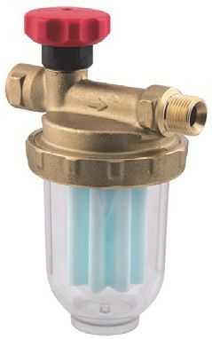
Informationen zur Sicherheit                                 DE

2     Informationen zur Sicherheit
2.1   Warnhinweise und Gefahrenklassen
      In dieser Betriebsanleitung finden Sie Warnhinweise, die auf potenzielle
      Gefahren und Risiken aufmerksam machen. Zusätzlich zu den Anweisungen
      in dieser Betriebsanleitung müssen Sie alle am Einsatzort des Produktes
      geltenden Bestimmungen, Normen und Sicherheitsvorschriften beachten.
      Stellen Sie vor Verwendung des Produkts sicher, dass Ihnen alle Bestimmun-
      gen, Normen und Sicherheitsvorschriften bekannt sind und dass sie befolgt
      werden.
      Warnhinweise sind in dieser Betriebsanleitung mit Warnsymbolen und Sig-
      nalwörtern gekennzeichnet. Abhängig von der Schwere einer Gefährdungs-
      situation werden Warnhinweise in unterschiedliche Gefahrenklassen unter-
      teilt.

                                    HINWEIS
      HINWEIS macht auf eine möglicherweise gefährliche Situation aufmerksam,
      die bei Nichtbeachtung Sachschäden zur Folge haben kann.

2.2   Bestimmungsgemäße Verwendung
      Dieses Produkt eignet sich ausschließlich für den Einsatz in Ein- und Zwei-
      strangsystemen zur kontinuierlichen Filterung folgender Brennstoffe in Heiz-
      ölverbraucheranlagen:
      Einstrangsysteme:
      •   Heizöl EL nach DIN 51603-1 und nach DIN SPEC 51603-6 mit 0 - 30 %
          Fettsäure-Methylester (FAME) nach EN 14214
      •   Dieselkraftstoff nach EN 590 mit bis zu 7 % Fettsäure-Methylester
          (FAME) nach EN 14214
      •   Bioheizöl und Biodiesel mit bis zu 30 % Fettsäure-Methylester (FAME)
          nach EN 14214
      •   Paraffinische Brennstoffe (HVO/GTL) anteilig mit 0 - 100 %

                                                            Heizölfilter         3
Informationen zur Sicherheit                                DE

      Zweistrangsysteme:
      •   Heizöl EL nach DIN 51603-1 und nach DIN SPEC 51603-6 mit 0 - 30 %
          Fettsäure-Methylester (FAME) nach EN 14214
      •   Dieselkraftstoff nach EN 590 mit bis zu 7 % Fettsäure-Methylester
          (FAME) nach EN 14214
      •   Paraffinische Brennstoffe (HVO/GTL) anteilig mit 0 - 100 %
      Eine andere Verwendung ist nicht bestimmungsgemäß und verursacht
      Gefahren.
      Stellen Sie vor Verwendung des Produkts sicher, dass das Produkt für die
      von Ihnen vorgesehene Verwendung geeignet ist. Berücksichtigen Sie dabei
      mindestens Folgendes:
      •   Alle am Einsatzort geltenden Bestimmungen, Normen und Sicherheits-
          vorschriften
      •   Alle für das Produkt spezifizierten Bedingungen und Daten
      •   Die Bedingungen der von Ihnen vorgesehenen Anwendung
      Führen Sie darüber hinaus eine Risikobeurteilung in Bezug auf die konkrete,
      von Ihnen vorgesehene Anwendung nach einem anerkannten Verfahren
      durch und treffen Sie entsprechende dem Ergebnis alle erforderlichen
      Sicherheitsmaßnahmen. Berücksichtigen Sie dabei auch die möglichen Fol-
      gen eines Einbaus oder einer Integration des Produkts in ein System oder in
      eine Anlage.
      Führen Sie bei der Verwendung des Produkts alle Arbeiten ausschließlich
      unter den in der Betriebsanleitung und auf dem Typenschild spezifizierten
      Bedingungen und innerhalb der spezifizierten technischen Daten und in
      Übereinstimmung mit allen am Einsatzort geltenden Bestimmungen, Nor-
      men und Sicherheitsvorschriften durch.

2.3   Vorhersehbare Fehlanwendung
      Das Produkt darf insbesondere in folgenden Fällen und für folgende Zwecke
      nicht angewendet werden:
      •   Einsatz mit unverdünnten Additiven, Alkoholen und Säuren
      •   Einsatz in Druckversorgungsanlagen ohne entsprechende Schutzvorkeh-
          rungen

                                                            Heizölfilter          4
Informationen zur Sicherheit                                 DE

2.4   Qualifikation des Personals
      Montage, Inbetriebnahme, Wartung und Außerbetriebnahme dieses Pro-
      dukts dürfen nur von einem qualifizierten Fachbetrieb vorgenommen werden,
      der über eine entsprechende Zertifizierung verfügt und folgende Anforderun-
      gen erfüllt:
      •   Einhaltung aller am Einsatzort des Produkts geltenden Bestimmungen,
          Normen und Sicherheitsvorschriften zum Umgang mit wassergefährden-
          den Stoffen.
      •   In Deutschland: Zertifizierung gemäß § 62 der Verordnung über Anlagen
          zum Umgang mit wassergefährdenden Stoffen (AwSV).
      Arbeiten an und mit diesem Produkt dürfen nur von Fachkräften vorgenom-
      men werden, die den Inhalt dieser Betriebsanleitung und alle zum Produkt
      gehörenden Unterlagen kennen und verstehen.
      Die Fachkräfte müssen aufgrund ihrer fachlichen Ausbildung, Kenntnisse
      und Erfahrungen in der Lage sein, mögliche Gefährdungen vorherzusehen
      und zu erkennen, die durch den Einsatz des Produkts entstehen können.
      Den Fachkräften müssen alle geltenden Bestimmungen, Normen und
      Sicherheitsvorschriften, die bei Arbeiten an und mit dem Produkt beachtet
      werden müssen, bekannt sein.

2.5   Persönliche Schutzausrüstung
      Verwenden Sie immer die erforderliche persönliche Schutzausrüstung.
      Berücksichtigen Sie bei Arbeiten an und mit dem Produkt auch, dass am Ein-
      satzort Gefährdungen auftreten können, die nicht direkt vom Produkt ausge-
      hen.

2.6   Veränderungen am Produkt
      Führen Sie ausschließlich solche Arbeiten an und mit dem Produkt durch, die
      in dieser Betriebsanleitung beschrieben sind. Nehmen Sie keine Verände-
      rungen vor, die in dieser Betriebsanleitung nicht beschrieben sind.

                                                            Heizölfilter          5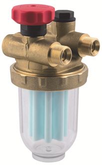
Transport und Lagerung                                  DE

3     Transport und Lagerung
      Das Produkt kann durch unsachgemäßen Transport und Lagerung beschä-
      digt werden.

                                   HINWEIS
    UNSACHGEMÄSSE HANDHABUNG
    • Stellen Sie sicher, dass während des Transports und der Lagerung des Pro-
      dukts die spezifizierten Umgebungsbedingungen eingehalten werden.
    • Benutzen Sie für den Transport die Originalverpackung.
    • Lagern Sie das Produkt nur in trockener, sauberer Umgebung.
    • Stellen Sie sicher, dass das Produkt bei Transport und Lagerung stoßge-
      schützt ist.
    Nichtbeachtung dieser Anweisungen kann zu Sachschäden führen.

                                                          Heizölfilter        6
Produktbeschreibung                                      DE

4     Produktbeschreibung
      Einstrangfilter Typ V 500 / V½ 500
      Das Produkt besteht aus einem Messing-Filtergehäuse mit Anschlüssen G3/8
      (Typ V1/2 500 mit Anschlüssen G1/2), einem Filtereinsatz, einer transparenten
      Filtertasse sowie einem Absperrventil.
      Einstrangfilter Typ R 500
      Das Produkt besteht aus einem Messing-Filtergehäuse mit Anschlüssen
      G3/8, einem Filtereinsatz, einer transparenten Filtertasse, einem Absperrven-
      til sowie einem Überströmventil.
      Zweistrangfilter Typ Z 500 / Z1/2 500
      Das Produkt besteht aus einem Messing-Filtergehäuse mit Anschlüssen G3/8
      (Typ Z1/2 500 mit Anschlüssen G1/2), einem Filtereinsatz, einer transparenten
      Filtertasse, einem Absperrventil sowie einem Rückflussverhinderer.

4.1   Anwendungsbeispiele

      Abbildung 1: Typ V 500 / V½ 500

                                                             Heizölfilter         7
Produktbeschreibung                  DE

Abbildung 2: Typ R 500

Abbildung 3: Typ Z 500 / Z½ 500

                                       Heizölfilter   8
Produktbeschreibung                                     DE

4.2   Technische Daten

        V   = Einstrangfilter
        R   = Einstrangfilter mit Rücklaufzuführung
        Z   = Zweistrangfilter

       ohne Kennzeichn. = Anschluss Tank/Brenner G3/8
       ½                = Anschluss Tank/Brenner G½
       500    = Zulässige Medien siehe
       Optimum "Bestimmungsgemäße Verwendung"
       Si    = Sinterkunststoffsieb 50-70 µm
       Fi    = Filzsieb
       St    = Stahlsieb

      Abbildung 4: Typenschlüssel

      Parameter                     Wert
      Umgebungstemperatur           Messing-Filtertasse: Max. 60 °C
      Betrieb                       Kunststoff-Filtertasse: Max. 40 °C
      Betriebsüberdruck             Messing-Filtertasse mit Messing-Überwurfmut-
                                    ter: Max. 6 bar
                                    Kunststoff-Filtertasse: Nur Saugbetrieb
      Saugdruck                     Max. -0,5 bar
      Prüfdruck                     6 bar
      Einbaulage                    Senkrecht – Filtertasse nach unten

                                                               Heizölfilter        9
Produktbeschreibung DE
Durchfluss-Nennleistung
Typ Stahl Filz Siku Siku
100 µm 50-75 µm 50-70 µm 50-70 µm
lang
V 500 320 290 250 255
V½-500 560 470 390 405
R 500 250 240 210 215
Z 500 220 200 200 205
Z½-500 500 400 310 325
Tabelle 1: Öldurchsatz in l/h bei p = 100 mbar nach EN 12514-2 bei 50 %-igem Ver-
schmutzungsgrad des Filtereinsatzes
Heizölfilter Ausführung „Optimum“ (mit langer Filtertasse) besitzen annä-
hernd die gleichen Durchfluss-Nennleistungen wie die Standard-Ausführun-
gen.
Heizölfilter 10Montage DE
5 Montage
Das Produkt wird vor dem Brenner installiert.
Das Produkt darf über oder unter dem maximalen Füllstand des Tanks ein-
gebaut werden.
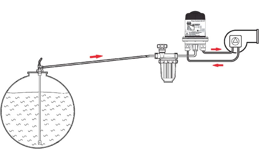
5.1 Montage vorbereiten für R 500
Stellen Sie sicher, dass die Brennerpumpe eine ausreichende Druckbe-
ständigkeit an der Rücklaufseite aufweist (siehe "Rücklaufdruck").
Abbildung 5: Rücklaufdruck
Der maximale Rücklaufstrom entspricht dem Fördervolumen der Pumpe, da
während der Vorbelüftungszeit der gesamte Volumenstrom in den Rücklauf
gefördert wird. Ein eventueller statischer Vordruck der Ölsäule addiert sich
zum maximalen Rücklaufdruck.
Wenn keine ausreichende Druckbeständigkeit an der Rücklaufseite der
Brennerpumpe vorhanden ist, empfehlen wir den Einsatz der automatischen
Heizölentlüfter Flow-Control oder der Filterentlüfter FloCo-Top.
Heizölfilter 11Montage DE
5.2 Querschnitt der Saugleitung ermitteln
Bei Umstellung von Zweistranganlagen auf Einstrang-Betrieb sinkt die Strö-
mungsgeschwindigkeit des Brennstoffs in der Saugleitung.
Stellen Sie sicher, dass der Querschnitt der Saugleitung DIN 4755-2
(Strömungsgeschwindigkeit 0,2 - 0,5 m/s) entspricht, um Luftansammlun-
gen in höher gelegenen Leitungsbereichen und Gefällstrecken zu vermei-
den (Störabschaltungen).
Berücksichtigen Sie grundsätzlich die Vorgaben des Anlagenherstellers.
5.3 Produkt montieren
Stellen Sie sicher, dass das Produkt nicht auf oder in der Nähe eines
unisolierten Kesselteils, oberhalb zu öffnender Klappen an Feuerungs-
stellen oder am Rauchkanal montiert wird.
Stellen Sie sicher, dass die Filtertasse senkrecht nach unten zeigt.
1. Montieren Sie das Pro-
dukt mit Hilfe des beige-
fügten Halters und den
beiden Bohrschrauben.
2. Verwenden Sie den Halter
als Schablone, um die
Bohrschrauben einzu-
schrauben.
HINWEIS
UNDICHTHEIT DES PRODUKTS
• Stellen Sie sicher, dass Sie eine Rohrverschraubung nach DIN 2353 mit
zylindrischem Einschraubgewinde (G-Gewinde) verwenden und die Rohr-
verschraubung mit einer Flachdichtung oder mit geeignetem Kleber eindich-
ten. Verwendung von Teflonband oder Hanf ist nicht zulässig.
Nichtbeachtung dieser Anweisungen kann zu Sachschäden führen.
Heizölfilter 12Inbetriebnahme DE
1. Montieren Sie die Saugleitung mit einer für den Produkttyp passenden
Rohrverschraubung G3/8 oder G1/2 nach DIN 2353 am Produkt. Das
Anzugsmoment beträgt 40 ±10 Nm.
2. Verwenden Sie für die Produkttypen V 500, R 500 und Z 500 eine
AFRISO Universal-Rohrverschraubung (Zubehör). Das Anzugsmoment
liegt für Ø 6 mm bei 18 ±3 Nm, für Ø 8 mm bei 15 ±5 Nm und für
Ø 10 mm bei 20 ±5 Nm. Die Montageanleitung liegt der Rohrverschrau-
bung bei.
3. Montieren Sie beim Produkttyp R 500 die Brennerschläuche. Achten Sie
bei der Montage auf saubere und unbeschädigte Dichtflächen. Das
Anzugsmoment beträgt 20 ±5 Nm.
HINWEIS
FUNKTIONSUNFÄHIGES PRODUKT
• Stellen Sie sicher, dass Sie die Brennerschläuche der Vor- und Rücklauflei-
tung nicht vertauschen.
Nichtbeachtung dieser Anweisungen kann zu Sachschäden führen.
6 Inbetriebnahme
1. Öffnen Sie das Absperrventil.
7 Betrieb
7.1 Druckbetrieb
Beim Einsatz des Produkts im Druckbetrieb muss dieses auf eine Mes-
sing-Filtertasse umgerüstet werden.
Stellen Sie sicher, dass Sie für diese Anwendung geeignete Vorkehrun-
gen treffen, die auch im Störfall (defekter Druckminderer) ein Überschrei-
ten des maximal zulässigen Betriebsdrucks (beispielsweise über ein
Überströmventil oder einen Druckschalter) verhindern.
Stellen Sie sicher, dass Sie unterhalb der Brennerschläuche und des
Heizölfilters eine Rückhalte-Einrichtung mit Leckage-Erkennung montie-
ren, über die ein Ölaustritt detektiert und der Brenner abgeschaltet wird.
Heizölfilter 13Betrieb DE
7.2 Luftansammlung in der Filtertasse
Je nach Art des Filtereinsatzes und des anlagebedingten Saugdruckes kann
es zu einem Luftpolster in der Filtertasse kommen. Bei einem neuem Filter-
einsatz befindet sich unter Umständen nur eine geringe Menge Brennstoff in
der Filtertasse. Das beeinträchtigt die Anlagenfunktion nicht (solange das
Innere des Filters mit Brennstoff benetzt ist).
Bei steigender Verschmutzung des Filters steigt der Saugdruck und die Fil-
tertasse füllt sich nach und nach komplett mit Brennstoff.
Wenn es aufgrund größerer Luftansammlung zu Betriebsstörungen kommt,
ist die Verwendung einer Kombination aus Heizölfilter und Entlüfter
(FloCo-Top-1 oder FloCo-Top-2) sinnvoll.
7.3 Einsatz in hochwassergefährdeten Gebieten
Das Produkt ist geeignet für hochwassergefährdete Gebiete und ist druck-
wasserdicht bis 10 mH2O (1 bar Außendruck).
Nach einem Hochwasserereignis muss das Produkt nicht getauscht werden.
HINWEIS
FUNKTIONSUNFÄHIGES PRODUKT
• Stellen Sie sicher, dass der Einstrangfilter mit Rücklaufzuführung (R 500 Si,
R 500 St, R 500 Fi) nach einem Hochwasserereignis getauscht wird.
Nichtbeachtung dieser Anweisungen kann zu Sachschäden führen.
Heizölfilter 14Wartung DE
8 Wartung
8.1 Wartungsintervalle
HINWEIS
UNGEEIGNETE REINIGUNGSMITTEL
• Stellen Sie sicher, dass Sie bei der Reinigung der Kunststoffteile lösemittel-
freie Reinigungsmittel verwenden.
Nichtbeachtung dieser Anweisungen kann zu Sachschäden führen.
Zeitpunkt Tätigkeit
Bei Bedarf Reinigen Sie die Kunststoffteile mit einer wässri-
gen Seifenlauge
Jährlich oder bei Bedarf Tauschen Sie den Filtereinsatz
Alle 5 Jahre Ersetzen Sie die Brennerschläuche der Ein-
strangfilter mit Rücklaufzuführung (R 500 Si;
R 500 St; R 500 Fi)
Spätestens nach Ersetzen Sie das Produkt
20 Jahren
Nach Hochwasser Ersetzen Sie den Einstrangfilter mit Rücklaufzu-
führung (R 500 Si; R 500 St; R 500 Fi)
Heizölfilter 15Wartung DE
8.2 Filtereinsatz tauschen
8.2.1 Filtereinsatz ausbauen
1 2
3 4
Heizölfilter 16Wartung DE
8.2.2 Filtereinsatz einbauen
Heizölfilter 17Störungsbeseitigung DE
9 Störungsbeseitigung
Störungen, die nicht durch die im Kapitel beschriebenen Maßnahmen besei-
tigt werden können, dürfen nur durch den Hersteller oder Fachkräfte beho-
ben werden.
Problem Mögliche Ursache Fehlerbehebung
Unregelmäßige Störab- Luftansammlungen in Legen Sie die Sauglei-
schaltungen des Bren- der Saugleitung durch tung korrekt aus (siehe
ners zu großen Leitungs- Kapitel "Querschnitt der
querschnitt der Sauglei- Saugleitung ermitteln")
tung
Luftansammlungen in Ersetzen Sie das Pro-
der Filtertasse durch dukt durch einen auto-
hohe Strömungsge- matischen Heizölentlüf-
schwindigkeiten und ter (FloCo-Top-1 oder
Saugdruck FloCo-Top-2)
Heizölfilter 18Störungsbeseitigung DE
Problem Mögliche Ursache Fehlerbehebung
Flüssigkeitssäule kann Geringfügige Undicht- Dichten Sie die zylindri-
nicht angezogen wer- heiten (beispielsweise sche Rohrverschrau-
den oder reißt ständig an Verschraubungen bungen mit Kup-
ab oder der Entnahmear- fer-Flachdichtungen
matur) können zu einem luftdicht ein
Lufteintritt in die Saug-
Verwenden Sie bei wei-
leitung führen, auch im chem/mittelhartem Kup-
Stillstand ferrohr zusätzlich eine
Stützhülse
Prüfen Sie sämtliche
Dichtflächen auf
Beschädigungen
Schließen Sie das
Absperrventil an der
Entnahmearmatur
Führen Sie eine Unter-
druckprüfung (mindes-
tens -0,6 bar) am Vor-
laufanschluss des
Entlüfters durch
Brennerpumpe erzeugt Führen Sie eine Saug-
keinen ausreichenden druckprüfung an der
Unterdruck Pumpe durch. Die
Pumpe muss mindes-
tens einen Unterdruck
von -0,4 bar aufbauen
Sonstige Störungen - Bitte wenden Sie sich
an die AFRISO-Service
Hotline
Heizölfilter 19Außerbetriebnahme und Entsorgung DE
10 Außerbetriebnahme und Entsorgung
Entsorgen Sie das Produkt nach den geltenden Bestimmungen, Normen und
Sicherheitsvorschriften.
Filter und Filtereinsätze dürfen nicht über den Hausmüll entsorgt werden.
1. Demontieren Sie das Produkt (siehe Kapitel "Montage"
in umgekehrter Reihenfolge).
2. Entsorgen Sie das Produkt.
11 Rücksendung
Vor einer Rücksendung Ihres Produkts müssen Sie sich mit uns in Verbin-
dung setzen (service@afriso.de).
12 Gewährleistung
Informationen zur Gewährleistung finden Sie in unseren Allgemeinen
Geschäftsbedingungen im Internet unter www.afriso.com oder in Ihrem Kauf-
vertrag.
Heizölfilter 20Ersatzteile und Zubehör DE
13 Ersatzteile und Zubehör
HINWEIS
UNGEEIGNETE TEILE
• Verwenden Sie nur Original Ersatz- und Zubehörteile des Herstellers.
Nichtbeachtung dieser Anweisung kann zu Sachschäden führen.
Produkt
Artikelbezeichnung Art.-Nr. Abbildung
Einstrangfilter
V 500 Si 20292
V 500 St 20294
Zweistrangfilter
Z 500 Si 20429
Z 500 St 20425
Z 500 Fi 20428
Einstrangfilter
R 500 Si (Rücklauf) 20281
R 500 St (Rücklauf) 20283
R 500 Fi (Rücklauf) 20282
Heizölfilter 21Ersatzteile und Zubehör DE
Ersatzteile und Zubehör
Artikelbezeichnung Art.-Nr. Abbildung
Filtertasse kurz (Typ 500) 20254 -
Kunststoff für Saugbetrieb
Filtertasse lang (Typ Optimum) 20258 -
Kunststoff für Saugbetrieb
Filtertasse (Typ 500) 20261 -
Messing für Druckbetrieb
Überwurfmutter M64 x 1,5 Messing 10 11 -
050008
Filtertasse (Typ 500) 20257 -
Kunststoff mit Ablassfunktion
Filtertasse (Typ Optimum) 20262 -
Kunststoff für Saugbetrieb
O-Ring für Filtertasse 20422 -
Ölfilterschlüssel zum Lösen 70060
der Überwurfmutter der Filtertasse
Rohrverschraubung G3/8 nach DIN 2353 -
mit Kupfer-Flachdichtung:
Rohr Ø 6 mm 20509
Rohr Ø 8 mm 20508
Rohr Ø 10 mm 20510
AFRISO Universal-Rohrverschraubung 20409
für Rohr Ø 6 mm, Ø 8 mm und Ø 10 mm
Heizölfilter 22Operating
instructions
Fuel oil filters
Single line filters V, R
Dual-line filter Z
Copyright 2021 AFRISO-EURO-INDEX GmbH. All rights reserved.
Lindenstraße 20
74363 Güglingen
Telephone +49 7135 102-0
MVV TB
C 2.15.23 Service +49 7135 102-211
EN 12514-2 Telefax +49 7135 102-147
info@afriso.com
www.afriso.com
Version: 11.2021.0
ID: 900.000.0062About these operating instructions EN
1 About these operating instructions
These operating instructions describe fuel oil filters (also referred to as "prod-
uct" in these operating instructions). These operating instructions are part of
the product.
• You may only use the product if you have fully read and understood these
operating instructions.
• Verify that these operating instructions are always accessible for any type
of work performed on or with the product.
• Pass these operating instructions as well as all other product-related doc-
uments on to all owners of the product.
• If you feel that these operating instructions contain errors, inconsisten-
cies, ambiguities or other issues, contact the manufacturer prior to using
the product.
These operating instructions are protected by copyright and may only be
used as provided for by the corresponding copyright legislation. We reserve
the right to modifications.
The manufacturer shall not be liable in any form whatsoever for direct or con-
sequential damage resulting from failure to observe these operating instruc-
tions or from failure to comply with directives, regulations and standards and
any other statutory requirements applicable at the installation site of the prod-
uct.
Fuel oil filters 2Information on safety EN
2 Information on safety
2.1 Safety messages and hazard categories
These operating instructions contain safety messages to alert you to poten-
tial hazards and risks. In addition to the instructions provided in these oper-
ating instructions, you must comply with all directives, standards and safety
regulations applicable at the installation site of the product. Verify that you are
familiar with all directives, standards and safety regulations and ensure com-
pliance with them prior to using the product.
Safety messages in these operating instructions are highlighted with warning
symbols and warning words. Depending on the severity of a hazard, the
safety messages are classified according to different hazard categories.
NOTICE
NOTICE indicates a hazardous situation, which, if not avoided, can result in
equipment damage.
2.2 Intended use
This product may exclusively be used for use in single-line systems and
dual-line systems for continuous filtration of the following fuels in fuel oil con-
suming systems:
Single-line systems:
• Fuel oil EL as per DIN 51603-1 and as per DIN SPEC 51603-6 with
0 - 30 % fatty acid methyl ester (FAME) as per EN 14214
• Diesel fuel as per EN 590 with up to 7 % fatty acid methyl ester (FAME)
as per EN 14214
• Biofuel and biodiesel with up to 30 % fatty acid methyl ester (FAME) as
biodiesel as per EN 14214
• Carburants paraffiniques (HVO/GTL) proportionnellement avec 0 - 100 %
Dual-line systems:
• Fuel oil EL as per DIN 51603-1 and as per DIN SPEC 51603-6 with
0 - 30 % fatty acid methyl ester (FAME) as per EN 14214
• Diesel fuel as per EN 590 with up to 7 % fatty acid methyl ester (FAME)
as per EN 14214
• Carburants paraffiniques (HVO/GTL) proportionnellement avec 0 - 100 %
Fuel oil filters 3Information on safety EN
Any use other than the application explicitly permitted in these operating
instructions is not permitted and causes hazards.
Verify that the product is suitable for the application planned by you prior to
using the product. In doing so, take into account at least the following:
• All directives, standards and safety regulations applicable at the installa-
tion site of the product
• All conditions and data specified for the product
• The conditions of the planned application
In addition, perform a risk assessment in view of the planned application,
according to an approved risk assessment method, and implement the
appropriate safety measures, based on the results of the risk assessment.
Take into account the consequences of installing or integrating the product
into a system or a plant.
When using the product, perform all work and all other activities in conjunc-
tion with the product in compliance with the conditions specified in the oper-
ating instructions and on the nameplate, as well as with all directives, stand-
ards and safety regulations applicable at the installation site of the product.
2.3 Predictable incorrect application
The product must never be used in the following cases and for the following
purposes:
• Use with undiluted additives, alcohols and acids
• Use in pressure supply systems without appropriate protection precau-
tions
2.4 Qualification of personnel
This product may only be mounted, commissioned, maintained and decom-
missioned by a qualified, specialised company which has all required certifi-
cations and which meets the following requirements:
• Compliance with all directives, standards and safety regulations concern-
ing handling of water-polluting substances as applicable at the installation
site of the product.
• In Germany: Certification as per § 62 "Verordnung über Anlagen zum
Umgang mit wassergefährdenden Stoffen" (AwSV)(Ordinance on Instal-
lations for Handling Water-Polluting Substances).
Only appropriately trained persons who are familiar with and understand the
contents of these operating instructions and all other pertinent product doc-
umentation are authorized to work on and with this product.
Fuel oil filters 4Transport and storage EN
These persons must have sufficient technical training, knowledge and expe-
rience and be able to foresee and detect potential hazards that may be
caused by using the product.
All persons working on and with the product must be fully familiar with all
directives, standards and safety regulations that must be observed for per-
forming such work.
2.5 Personal protective equipment
Always wear the required personal protective equipment. When performing
work on and with the product, take into account that hazards may be present
at the installation site which do not directly result from the product itself.
2.6 Modifications to the product
Only perform work on and with the product which is explicitly described in
these operating instructions. Do not make any modifications to the product
which are not described in these operating instructions.
3 Transport and storage
The product may be damaged as a result of improper transport or storage.
NOTICE
INCORRECT HANDLING
• Verify compliance with the specified ambient conditions during transport or
storage of the product.
• Use the original packaging when transporting the product.
• Store the product in a clean and dry environment.
• Verify that the product is protected against shocks and impact during trans-
port and storage.
Failure to follow these instructions can result in equipment damage.
Fuel oil filters 5Product description EN
4 Product description
Single-line filter type V 500 / V½ 500
The product consists of a brass filter housing with connections G3/8 (type
V1/2 500 with connections G1/2), a filter insert, a transparent filter cup and a
shutoff-valve.
Single line filter type R 500
The product consists of a brass filter housing with connections G3/8, a filter
insert, a transparent filter cup, a shutoff-valve and a bypass valve.
Dual-line filters type Z 500 / Z1/2 500
The product consists of a brass filter housing with connections G3/8 (type
Z1/2 500 with connections G1/2), a filter insert, a transparent filter cup, a shut-
off-valve and a backflow preventer.
4.1 Application examples
Fig. 1: Type V 500 / V½ 500
Fuel oil filters 6Product description EN
Fig. 2: Type R 500
Fig. 3: Type Z 500 / Z½ 500
Fuel oil filters 7Product description EN
4.2 Technical data
V = single-line filter
R = single-line filter with return line supply
Z = dual-line filter
No designation = Connection tank/burner G3/8
½ = Connection tank/burner G½
500 = Approved media see
Optimum "Intended use"
Si = Sintered plastic sieve 50-70 µm
Fi = Felt sieve
St = Steel sieve
Fig. 4: Type code
Parameter Value
Ambient temperature Brass filter cup: Max. 60 °C
operation Plastic filter cup: Max. 40 °C
Operating overpressure Brass filter cup with brass union nut: Max. 6 bar
Plastic filter cup: Suction mode only
Suction pressure Max. -0.5 bar
Test pressure 6 bar
Mounting position Vertical - with filter cup down
Fuel oil filters 8Product description EN
Nominal flow rate
Type Steel Felt Sintered Sintered
100 µm 50-75 µm plastic plastic
50-70 µm 50-70 µm
long
V 500 320 290 250 255
V½-500 560 470 390 405
R 500 250 240 210 215
Z 500 220 200 200 205
Z½-500 500 400 310 325
Table 1: Oil flow rate in l/h with p = 100 mbar as per EN 12514-2 at pollution degree
of 50 % of filter insert
Fuel oil filters version "Optimum" (with long filter cup) have almost the same
nominal flow rates as the standard versions.
Fuel oil filters 9Mounting EN
5 Mounting
Install the product upstream of the burner.
The product may be installed above or below the maximum tank level.
5.1 Preparing mounting of R 500
Verify that the burner pump has a sufficient pressure resistance at the
return end (see "Return pressure").
Fig. 5: Return pressure
The maximum return flow corresponds to the pump capacity since the entire
volume flow is pumped into the return line during the pre-aeration time. Any
static inlet pressure of the oil column is added to the maximum return pres-
sure.
If the pressure resistance is not sufficient at the return side of the burner
pump, it is recommended to use the automatic fuel oil de-aerator Flow-Con-
trol or the filter de-aerator FloCo-Top.
Fuel oil filters 10Mounting EN
5.2 Determining the cross section of the suction line
When dual-pipe systems are converted to single-pipe operation, the flow rate
of the fuel in the suction line is reduced.
Verify that the cross section of the suction line complies with DIN 4755-2
(flow rate 0.2 to 0.5 m/s) in order to help avoid air cushions in higher pipe
sections and pipes with gradients (shutdowns due to error conditions).
Consider the specifications and instructions of the system manufacturer.
5.3 Mounting the product
Verify that the product is not mounted the product on top of or next to a
non-insulated boiler part, above opening dampers at furnaces or to the
flue gas pipe.
Verify that the filter cup vertically to the bottom.
1. Mount the product using
the enclosed bracket and
two self-tapping screws.
2. Use the bracket as a tem-
plate when screwing in the
self-tapping screws.
NOTICE
LEAKING PRODUCT
• Verify that you use a screwed pipe connection as per DIN 2353 with cylindri-
cal thread (G thread) and seal the screwed pipe connection with a flat gasket
or with suitable glue. Do not use Teflon tape or hemp.
Failure to follow these instructions can result in equipment damage.
Fuel oil filters 11Commissioning EN
1. Mount the suction line to the product using a suitable screwed pipe con-
nection G3/8 or G1/2 as per DIN 2353. The tightening torque is 40 ±10 Nm.
2. Use an AFRISO universal screwed pipe connection (accessories) for
product types V 500, R 500 and Z 500. The tightening torque for Ø 6 mm
is 18 ±3 Nm; for Ø 8 mm it is 15 ±5 Nm; for Ø 10 mm it is 20 ±5 Nm. The
mounting instructions are provided with the screwed pipe connection.
3. Mount the burner hoses (product type R 500). Before mounting, make
sure the sealing surfaces are clean and not damaged. The tightening
torque is 20 ±5 Nm.
NOTICE
INOPERABLE PRODUCT
• Verify that you do not interchange the burner hoses for the flow line and the
return line.
Failure to follow these instructions can result in equipment damage.
6 Commissioning
1. Open the shut-off valve.
7 Operation
7.1 Pressure mode
If the product is used in pressure mode, the product must be used with a
brass filter cup.
In the case of such applications, take appropriate measures to keep the
maximum permissible operating pressure from being exceeded even in
the case of error conditions (defective pressure reducer), for example, by
means of a bypass valve or a pressure switch, etc.
Verify that a collection facility with leak detection is installed below the
burner hoses and the fuel oil filter by means of which leaking oil is
detected and the burner is switched off.
Fuel oil filters 12Operation EN
7.2 Air in the filter cup
Depending on the filter insert and the suction pressure of the system, an air
cushion may form in the filter cup. If the filter insert is new, there may be just
a little volume of fuel in the filter cup. This does not affect the operation of the
system (as long as the inside of the filter is wetted with fuel).
With increasing pollution of the filter, the suction pressure increases and the
filter cup is completely filled with fuel over time.
If major accumulations of air result in malfunctions, it is advisable to use a
combination of fuel oil filter and de-aerator (FloCo-Top-1 or FloCo-Top-2).
7.3 Use in flood hazard areas
The product is suitable for use in flood hazard areas; it is watertight up to
10 mH2O (1 bar pressure).
The product does not have to be replaced after a flood.
NOTICE
INOPERABLE PRODUCT
• Ensure that the single-line filter with return supply (R 500 Si, R 500 St,
R 500 Fi) is replaced after a flood.
Failure to follow these instructions can result in equipment damage.
Fuel oil filters 13Maintenance EN
8 Maintenance
8.1 Maintenance intervals
NOTICE
UNSUITABLE CLEANING AGENTS
• Verify that you use only cleaning agents which do not contain solvents for
cleaning the plastic parts.
Failure to follow these instructions can result in equipment damage.
When Activity
If required Clean the plastic parts with soap suds
Annually or if required Replace the filter insert
Every 5 years Replace the burner hoses of the single-line filters
with return supply (R 500 Si; R 500 St; R 500 Fi)
No later than after Replace the product
20 years
After a flood Replace the single-line filter with return supply
(R 500 Si; R 500 St; R 500 Fi)
Fuel oil filters 14Maintenance EN
8.2 Replacing the filter insert
8.2.1 Dismounting the filter insert
1 2
3 4
Fuel oil filters 15Maintenance EN
8.2.2 Mounting the filter insert
Fuel oil filters 16Troubleshooting EN
9 Troubleshooting
Any malfunctions that cannot be removed by means of the measures
described in this chapter may only be repaired by the manufacturer or by
qualified persons.
Problem Possible reason Repair
Burner switches off at Air accumulations in the Properly rate the suction
irregular intervals due to suction line because line (see chapter "Deter-
malfunctions pipe cross section is too mining the cross section
great of the suction line")
Air accumulation in the Replace the product by
filter cup due to high an automatic fuel oil
flow rates and suction de-aerator (FloCo-Top-1
pressure or FloCo-Top-2)
Problem Possible reason Repair
Liquid cannot be sucked Small leaks (for exam- Use cylindrical screwed
in or steady flow keeps ple, at the screw con- pipe connections and
being interrupted nections or the with- seal them with flat cop-
drawal fitting) can cause per gaskets (air-tight)
air to get into the suction Use a stiffener in the
line, even when the sys- case of soft or semi-soft
tem is idle
copper pipes
Check all sealing sur-
faces for damage
Close the shut-off valve
at the withdrawal fitting
Perform a vacuum test
(at least -0.6 bar) at the
flow connection of the
de-aerator
Burner pump does not Perform a suction test at
generate sufficient vac- the pump. The pump
uum must generate a vac-
uum of at least -0.4 bar
Other malfunctions - Contact the AFRISO
service hotline
Fuel oil filters 17Decommissioning, disposal EN
10 Decommissioning, disposal
Dispose of the product in compliance with all applicable directives, standards
and safety regulations.
Filters and filter inserts must not be disposed of together with the normal
household waste.
1. Dismount the product (see chapter "Mounting", reverse
sequence of steps).
2. Dispose of the product.
11 Returning the device
Get in touch with us before returning your product (service@afriso.de).
12 Warranty
See our terms and conditions at www.afriso.com or your purchase contract
for information on warranty.
Fuel oil filters 18Spare parts and accessories EN
13 Spare parts and accessories
NOTICE
UNSUITABLE PARTS
• Only use genuine spare parts and accessories provided by the manufac-
turer.
Failure to follow these instructions can result in equipment damage.
Product
Product designation Part no. Figure
Single line filters
V 500 Si 20292
V 500 St 20294
Dual-line filter
Z 500 Si 20429
Z 500 St 20425
Z 500 Fi 20428
Single line filters
R 500 Si (return) 20281
R 500 St (return) 20283
R 500 Fi (return) 20282
Fuel oil filters 19Spare parts and accessories EN
Spare parts and accessories
Product designation Part no. Figure
Filter cup short (type 500) 20254 -
Plastic, for suction mode
Filter cup long (type Optimum) 20258 -
Plastic, for suction mode
Filter cup brass (type 500) 20261 -
Brass, for pressure mode
Union nut M 64 x 1.5 brass 10 11 -
050008
Filter cup (type 500) 20257 -
Plastic, with drain function
Filter cup (type Optimum) 20262 -
Plastic, for suction mode
O ring for filter cup 20422 -
Oil filter spanner for loosening 70060
the union nut of the filter cup
Screwed pipe connection G3/8 as per -
DIN 2353 with flat copper gasket:
Pipe Ø 6 mm 20509
Pipe Ø 8 mm 20508
Pipe Ø 10 mm 20510
AFRISO universal screwed pipe connec- 20409
tion
for pipes Ø 6 mm, Ø 8 mm and Ø 10 mm
Fuel oil filters 20Notice technique
Filtre fuel
Filtre monotube V, R
Filtre à deux tubes Z
Copyright 2021 AFRISO-EURO-INDEX GmbH. Tous droits réservés.
Lindenstraße 20
74363 Güglingen
MVV TB Téléphone +49 7135 102-0
C 2.15.23 Service clientèle +49 7135 102-211
EN 12514-2 Téléfax +49 7135 102-147
info@afriso.com
www.afriso.com
Version: 11.2021.0
ID: 900.000.0062La présente notice technique FR
1 La présente notice technique
Cette notice technique contient la description des filtres fuel (dénommé
ci-après "produit"). Cette notice technique fait partie du produit.
• Utilisez le produit seulement après que vous aurez lu et compris intégra-
lement la notice technique.
• Assurez-vous que la notice technique est disponible en permanence pour
toutes les opérations relatives au produit.
• Transmettez la notice technique et toute la documentation relative au pro-
duit à tous les utilisateurs du produit.
• Si vous êtes d'avis que la notice technique contient des erreurs, des
contradictions ou des ambiguïtés, adressez-vous au fabricant avant d'uti-
liser le produit.
Cette notice technique est protégée au titre de la propriété intellectuelle ; elle
doit être utilisée exclusivement dans le cadre autorisé par la loi. Sous réserve
de modifications.
La responsabilité du fabricant ou la garantie ne pourra être engagée pour des
dommages ou dommages consécutifs résultant d'une inobservation de cette
notice technique ou des directives, règlements et normes en vigueur sur le
lieu d'installation du produit.
Filtre fuel 2Informations sur la sécurité FR
2 Informations sur la sécurité
2.1 Consignes de sécurité et classes de risques
Cette notice technique contient des consignes de sécurité destinées à attirer
l'attention sur les dangers et les risques. Outre les instructions contenues
dans cette notice technique, il faut vous assurer de l'observation de tous les
règlements, normes et consignes de sécurité en vigueur sur le lieu d'instal-
lation du produit. Avant d'utiliser le produit assurez-vous que tous les règle-
ments, normes et consignes de sécurité sont connus et respectés.
Dans cette notice technique les consignes de sécurité sont identifiables à
l'aide de symboles de mise en garde et de mots d'avertissement. En fonction
de la gravité du risque les consignes de sécurité sont réparties dans diffé-
rentes classes de risques.
AVIS
AVIS signale une situation potentiellement dangereuse qui, si elle n'est pas
évitée, peut entraîner un dommage matériel.
2.2 Usage normal
Le produit est destiné exclusivement à l'utilisation dans les systèmes mono-
tube et bitube et au filtrage en continu des fuels suivants dans les systèmes
de consommation de fuel :
Systèmes monotube :
• Fuel domestique EL selon DIN 51603-1 et selon DIN SPEC 51603-6
contenant 0 - 30 % d'ester méthylique d'acide gras (EMAG) selon
EN 14214
• Gazole selon EN 590, contenant jusqu'à 7 % d'ester méthylique d'acide
gras (EMAG) selon EN 14214
• Biofioul et biodiesel contenant jusqu'à 30 % d'ester méthylique d'acide
gras (EMAG) selon EN 14214
• Paraffinic fuels (HVO/GTL) proportionally with 0 - 100 %
Filtre fuel 3Informations sur la sécurité FR
Systèmes bitube :
• Fuel domestique EL selon DIN 51603-1 et selon DIN SPEC 51603-6
contenant 0 - 30 % d'ester méthylique d'acide gras (EMAG) selon
EN 14214
• Gazole selon EN 590, contenant jusqu'à 7 % d'ester méthylique d'acide
gras (EMAG) selon EN 14214
• Paraffinic fuels (HVO/GTL) proportionally with 0 - 100 %
Toute autre utilisation n'est pas conforme et cause des risques.
Avant d'utiliser le produit, assurez-vous que le produit est adapté à l'usage
que vous prévoyez. À cet effet, tenez compte au moins de ce qui suit :
• Tous les règlements, normes et consignes de sécurité sur le lieu d'instal-
lation
• Toutes les conditions et données spécifiées pour le produit
• Toutes les conditions d'application que vous prévoyez
En outre effectuez une évaluation des risques portant sur l'application
concrète que vous prévoyez à l'aide d'un procédé reconnu et prenez toutes
les mesures de sécurité nécessaires correspondant au résultat. Prenez
aussi en compte les conséquences possibles du montage ou de l'intégration
du produit dans un système ou une installation.
Pendant l'utilisation du produit effectuez toutes les opérations exclusivement
dans les conditions spécifiées dans cette notice technique et sur la plaque
signalétique, conformément aux données techniques spécifiées et en accord
avec tous les règlements, normes et consignes de sécurité en vigueur sur le
lieu d'installation.
2.3 Utilisation non conforme prévisible
Le produit ne doit, en particulier, pas être utilisé dans les cas suivants :
• Utilisation avec des additifs non dilués, alcools et acides
• Utilisation dans les systèmes d'alimentation de pression sans précautions
de protection correspondantes
2.4 Qualification du personnel
Le montage, la mise en service, la maintenance et la mise hors service de
ce produit ne peuvent être effectuées que par une entreprise spécialisée
qualifiée possédant la certification appropriée et répondant aux exigences
suivantes :
Filtre fuel 4Transport et stockage FR
• Conformité à toutes les réglementations, normes et réglementations de
sécurité applicables sur le lieu d'utilisation du produit concernant les
substances susceptibles de polluer l'eau.
• En Allemagne : Certification selon l'article 62 de l'ordonnance allemande
sur les installations contenant des substances susceptibles de polluer
l'eau "Zertifizierung gemäß § 62 der Verordnung über Anlagen zum
Umgang mit wassergefährdenden Stoffen" (AwSV).
Seul le personnel dûment qualifié est autorisé à travailler sur le produit et
avec celui-ci après qu'il aura connu et compris le contenu de cette notice
technique, ainsi que toute la documentation faisant partie du produit.
S'appuyant sur sa formation spécialisée, ses connaissances et ses expé-
riences, le personnel qualifié doit être en mesure de prévoir et reconnaître
les dangers qui peuvent être causés par l'utilisation du produit.
Tous les règlements, normes et consignes de sécurité en vigueur sur le lieu
d'installation doivent être connus du personnel qualifié travaillant sur le pro-
duit et avec celui-ci.
2.5 Équipement de protection individuelle
Utilisez toujours l'équipement de protection individuel requis. En travaillant
sur le produit et avec celui-ci, tenez compte des dangers susceptibles de se
présenter sur le lieu d'installation lesquels n'émanent pas directement du
produit.
2.6 Modification du produit
En travaillant sur le produit et avec celui-ci, effectuez exclusivement les opé-
rations décrites dans cette notice technique. N'effectuez pas de modifica-
tions non décrites dans cette notice technique.
3 Transport et stockage
Un transport et un stockage inadéquats risquent de causer des dommages
au produit.
Filtre fuel 5Transport et stockage FR
AVIS
MANUTENTION INAPPROPRIÉE
• Assurez-vous que les conditions ambiantes spécifiées sont respectées pen-
dant le transport et le stockage.
• Utilisez l'emballage d'origine pour le transport.
• Stockez le produit dans un lieu sec et propre.
• Assurez-vous que le produit est à l'abri des chocs pendant le transport et le
stockage.
La non-observation de ces instructions peut causer des dommages maté-
riels.
Filtre fuel 6Description du produit FR
4 Description du produit
Filtre monotube type V 500 / V½ 500
Le produit est composé d'un boîtier filtre en laiton avec raccords G3/8 (type
V1/2 500 avec raccords G1/2), d'un élément filtrant, d'un bol de filtre transpa-
rent et d'une vanne d'arrêt.
Filtre monotube type R 500
Le produit est composé d'un boîtier filtre en laiton avec raccords G3/8, d'un
élément filtrant, d'un bol de filtre transparent, d'une vanne d'arrêt et d'un
réducteur pression.
Filtre à deux tubes type Z 500 / Z1/2 500
Le produit est composé d'un boîtier filtre en laiton avec raccords G3/8 (type
Z1/2 500 avec raccords G1/2), d'un élément filtrant, d'un bol de filtre transpa-
rent, d'une vanne d'arrêt et d'un clapet anti-retour.
4.1 Exemples d'application
Figure 1: Type V 500 / V½ 500
Filtre fuel 7Description du produit FR
Figure 2: Type R 500
Figure 3: Type Z 500 / Z½ 500
Filtre fuel 8Description du produit FR
4.2 Caractéristiques techniques
V = Filtre monotube
R = Filtre monotube avec retour
Z = Filtre à deux tubes
Sans désign. = Raccordement réservoir/brû-
½ leur G3/8
500 = Liquides approuvés voir
Optimum "Usage normal"
Si = Tamis en matière plastique Siku 50-70 µm
Fi = Tamis feutre
St = Tamis en acier
Figure 4: Code de types
Paramètre Valeur
Température ambiante Bol de filtre laiton : 60 °C max.
service Bol de filtre en matière plastique : 40 °C max.
Pression de service Bol de filtre avec écrou-raccord en laiton : 6 bar
max.
Bol de filtre en matière plastique : mode aspira-
tion uniquement
Pression d'aspiration Max. -0,5 bar
Pression d'essai 6 bar
Position de montage Vertical – bol de filtre vers le bas
Filtre fuel 9Description du produit FR
Débit nominal
Type Acier Feutre Siku Siku
100 µm 50-75 µm 50-70 µm 50-70 µm
long
V 500 320 290 250 255
V½-500 560 470 390 405
R 500 250 240 210 215
Z 500 220 200 200 205
Z½-500 500 400 310 325
Tableau 1 : Débit fuel en l/h avec p = 100 mbar selon EN 12514-2, dégrée d'encras-
sement de l'élément filtrant de 50 %
Les filtres fuel "Optimum" (avec bol de filtre long) ont presque les mêmes
débits nominaux que les filtres fuel standards.
Filtre fuel 10Montage FR
5 Montage
Le produit est à installer en amont du brûleur.
Le produit peut être monté au-dessus ou en dessous du niveau maximum du
réservoir.
5.1 Préparation du montage pour R 500
Assurez-vous que la pompe du brûleur a une résistance à la pression suf-
fisante du côté retour (voir "Pression retour").
Figure 5: Pression retour
Le débit de retour maximum correspond à la capacité de la pompe puisque
le débit volumique total est pompé dans la conduite de retour pendant le
temps de pré-aération. Toute pression d'entrée statique de la colonne d'huile
s’additionne pour donner la pression de retour maximale.
Si la résistance à la pression n'est pas suffisante sur le côté retour de la
pompe du brûleur, il est recommandé d'utiliser les purgeurs d'air automa-
tiques Flow-Control ou purgeurs d'air automatiques avec filtre FloCo-Top.
Filtre fuel 11Montage FR
5.2 Déterminer la section de la conduite d'aspiration
En cas de conversion d'un système à deux conduites en un système à
conduite unique, il y a ralentissement de l'écoulement du fuel dans la
conduite d'aspiration.
Assurez-vous que la section de conduite d'aspiration conforme à
DIN 4755-2 (vitesse d'écoulement de 0,2 à 0,5 m/s) pour éviter l'accumu-
lation d'air dans les tronçons de la conduite et les segments en déclivité
se trouvant dans les parties supérieures (coupures par défaillance).
Tenez toujours compte des spécifications et des instructions du fabricant du
système.
5.3 Montage du produit
Évitez tout montage du produit sur une partie non isolée de la chaudière
ou à proximité d'une telle partie, au-dessus de clapets à ouvrir aux
endroits de combustion ou au tuyau de tirage.
Vérifiez que le bol de filtre est en position verticale et dirigé vers le bas.
1. Fixez le produit à l'aide du
support fourni et les deux
vis autoperceuses.
2. Utilisez le support comme
gabarit pour visser les vis
autoperceuses.
AVIS
INÉTANCHÉITÉ DU PRODUIT
• Utilisez un raccord tube selon DIN 2353 avec filetage cylindrique (filetage G)
et assurez l'étanchéité du raccord tube avec une garniture plate ou une colle
adaptée. N'utilisez pas du ruban téflon ou du chanvre.
La non-observation de ces instructions peut causer des dommages maté-
riels.
Filtre fuel 12Mise en service FR
1. Montez le tube d'aspiration sur le produit à l'aide d'un raccord tube appro-
prié G3/8 ou G1/2 selon DIN 2353. Le couple de serrage est de 40 ±10 Nm.
2. Utilisez un raccord tube universel AFRISO (accessoire) pour les types de
produit V 500, R 500 et Z 500. Couple de serrage : pour Ø 6 mm de
18 ±3 Nm, pour Ø 8 mm de 15 ±5 Nm et pour Ø 10 mm de 20 ±5 Nm.
Les instructions de montage sont fournies avec le raccord tube.
3. Type de produit R 500 : raccordez les flexibles du brûleur. Les surfaces
d'étanchéité doivent être intactes et propres. Le couple de serrage est de
20 ±5 Nm.
AVIS
PRODUIT NON OPÉRATIONNEL
• Assurez-vous de ne pas invertir les tuyaux du brûleur pour les conduites
départ et retour.
La non-observation de ces instructions peut causer des dommages maté-
riels.
6 Mise en service
1. Ouvrez la vanne d'arrêt.
7 Service
7.1 Mode pression
Si le produit est utilisé en mode pression, le produit doit être utilisé avec un
bol de filtre en laiton.
Pour cette application prenez des précautions appropriées (pressostat,
soupape de décharge, etc.) ; en cas d'incident (réducteur de pression
défectueux, etc.), la pression d'alimentation ne doit pas excéder la valeur
admissible.
Assurez-vous qu'un récipient collecteur avec détection de fuite est installé
sous les tuyaux du brûleur et le filtre fuel qui permet de détecter une fuite
d'huile et d'éteindre le brûleur.
Filtre fuel 13Service FR
7.2 Accumulations d'air dans le bol de filtre
Selon le type d'élément filtrant et la pression d'aspiration liée au système, il
peut y avoir un coussin d'air dans le bol de filtre. Avec un nouvel élément fil-
trant, il se peut qu'il n'y ait qu'une petite quantité de fuel dans le bol de filtre.
Cela n'affecte pas le fonctionnement du système (tant que l'intérieur du filtre
est humidifié avec du carburant).
À mesure que le filtre devient plus sale, la pression d'aspiration augmente et
le bol de filtre se remplit progressivement complètement de fuel.
Si des grandes accumulations d'air entraînent des dysfonctionnements, il est
conseillé d'utiliser une combinaison de filtre fuel et de purgeur d'air
(FloCo-Top-1 ou FloCo-Top-2).
7.3 Utilisation dans zones à risque d'inondation
Le produit est approprié à l'utilisation dans des zones à risque d'inondation
et étanche à l'eau jusqu'à 10 mH2O (1 bar pression).
Le produit ne doit pas être remplacé après une inondation.
AVIS
PRODUIT NON OPÉRATIONNEL
• Vérifiez que le filtre monotube avec retour (R 500 Si, R 500 St, R 500 Fi) est
remplacé après une inondation.
La non-observation de ces instructions peut causer des dommages maté-
riels.
Filtre fuel 14Sie können auch lesen