Betriebsanleitung Operating instructions Notice technique
←
→
Transkription von Seiteninhalten
Wenn Ihr Browser die Seite nicht korrekt rendert, bitte, lesen Sie den Inhalt der Seite unten

Betriebsanleitung
Operating instructions
Notice technique
DTA 20 E
Copyright 2022 AFRISO-EURO-INDEX GmbH. Alle Rechte vorbehalten.
Lindenstraße 20
74363 Güglingen
Telefon +49 7135 102-0
Service +49 7135 102-211
Telefax +49 7135 102-147
info@afriso.com
www.afriso.com
Version: 01.2022.0
ID: 900.000.0900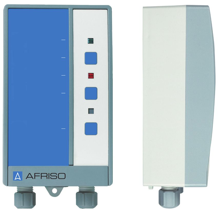
Betriebsanleitung
Digitaler Tankinhaltsanzeiger
DTA 20 E
Copyright 2022 AFRISO-EURO-INDEX GmbH. Alle Rechte vorbehalten.
Lindenstraße 20
74363 Güglingen
Telefon +49 7135 102-0
Service +49 7135 102-211
Telefax +49 7135 102-147
info@afriso.com
www.afriso.com
Version: 01.2022.0
ID: 900.000.0900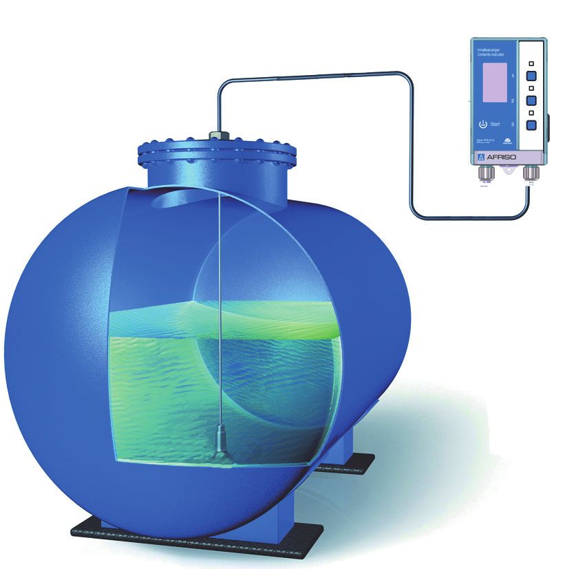
Über diese Betriebsanleitung                                     DE

1   Über diese Betriebsanleitung
    Diese Betriebsanleitung beschreibt den Digitalen Tankinhaltsanzeiger
    „DTA 20 E“ (im Folgenden auch „Produkt“). Diese Betriebsanleitung ist Teil
    des Produkts.
    •   Sie dürfen das Produkt erst benutzen, wenn Sie die Betriebsanleitung
        vollständig gelesen und verstanden haben.
    •   Stellen Sie sicher, dass die Betriebsanleitung für alle Arbeiten an und mit
        dem Produkt jederzeit verfügbar ist.
    •   Geben Sie die Betriebsanleitung und alle zum Produkt gehörenden Unter-
        lagen an alle Benutzer des Produkts weiter.
    •   Wenn Sie der Meinung sind, dass die Betriebsanleitung Fehler, Wider-
        sprüche oder Unklarheiten enthält, wenden Sie sich vor Benutzung des
        Produkts an den Hersteller.
    Diese Betriebsanleitung ist urheberrechtlich geschützt und darf ausschließ-
    lich im rechtlich zulässigen Rahmen verwendet werden. Änderungen vorbe-
    halten.
    Für Schäden und Folgeschäden, die durch Nichtbeachtung dieser Betriebs-
    anleitung sowie Nichtbeachten der am Einsatzort des Produkts geltenden
    Vorschriften, Bestimmungen und Normen entstehen, übernimmt der Herstel-
    ler keinerlei Haftung oder Gewährleistung.

                                                              DTA 20 E            2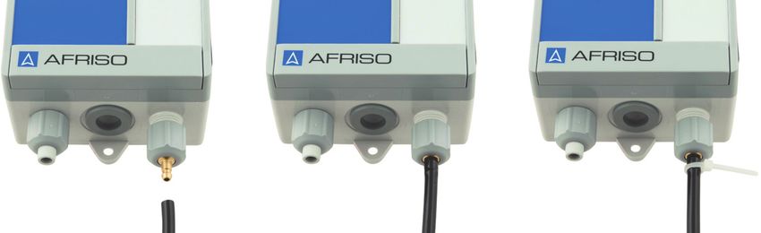
Informationen zur Sicherheit                                 DE

2     Informationen zur Sicherheit
2.1   Warnhinweise und Gefahrenklassen
      In dieser Betriebsanleitung finden Sie Warnhinweise, die auf potenzielle
      Gefahren und Risiken aufmerksam machen. Zusätzlich zu den Anweisungen
      in dieser Betriebsanleitung müssen Sie alle am Einsatzort des Produktes gel-
      tenden Bestimmungen, Normen und Sicherheitsvorschriften beachten. Stel-
      len Sie vor Verwendung des Produktes sicher, dass Ihnen alle Bestimmun-
      gen, Normen und Sicherheitsvorschriften bekannt sind und dass sie befolgt
      werden.
      Warnhinweise sind in dieser Betriebsanleitung mit Warnsymbolen und Sig-
      nalwörtern gekennzeichnet. Abhängig von der Schwere einer Gefährdungs-
      situation werden Warnhinweise in unterschiedliche Gefahrenklassen unter-
      teilt.

                                       HINWEIS
      HINWEIS macht auf eine möglicherweise gefährliche Situation aufmerksam,
      die bei Nichtbeachtung Sachschäden zur Folge haben kann.

2.2   Bestimmungsgemäße Verwendung
      Dieses Produkt eignet sich ausschließlich zur Füllstandmessung folgender
      Flüssigkeiten:
      •   Heizöl (Dichte 0,84 g/cm³)
      •   Wasser (Dichte 1 g/cm³)
      •   Paraffinische Brennstoffe HVO (~0,78 g/cm³) und GTL (~0,76 g/cm³)
      •   Variabel (Dichte einstellbar von 0,5 - 1,5 g/cm³)
      Eine andere Verwendung ist nicht bestimmungsgemäß und verursacht
      Gefahren.
      Stellen Sie vor Verwendung des Produkts sicher, dass das Produkt für die
      von Ihnen vorgesehene Verwendung geeignet ist. Berücksichtigen Sie dabei
      mindestens folgendes:
      •   Alle am Einsatzort geltenden Bestimmungen, Normen und Sicherheits-
          vorschriften
      •   Alle für das Produkt spezifizierten Bedingungen und Daten
      •   Die Bedingungen der von Ihnen vorgesehenen Anwendung

                                                              DTA 20 E           3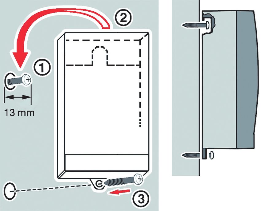
Informationen zur Sicherheit                                DE

      Führen Sie darüber hinaus eine Risikobeurteilung in Bezug auf die konkrete,
      von Ihnen vorgesehene Anwendung nach einem anerkannten Verfahren
      durch und treffen Sie entsprechende dem Ergebnis alle erforderlichen
      Sicherheitsmaßnahmen. Berücksichtigen Sie dabei auch die möglichen Fol-
      gen eines Einbaus oder einer Integration des Produkts in ein System oder in
      eine Anlage.
      Führen Sie bei der Verwendung des Produkts alle Arbeiten ausschließlich
      unter den in der Betriebsanleitung und auf dem Typenschild spezifizierten
      Bedingungen und innerhalb der spezifizierten technischen Daten und in
      Übereinstimmung mit allen am Einsatzort geltenden Bestimmungen, Normen
      und Sicherheitsvorschriften durch.

2.3   Vorhersehbare Fehlanwendung
      Das Produkt darf insbesondere in folgenden Fällen und für folgende Zwecke
      nicht angewendet werden:
      •   Explosionsgefährdete Umgebung
          - Bei Betrieb in explosionsgefährdeten Bereichen kann Funkenbildung zu
            Verpuffungen, Brand oder Explosionen führen
      •   Einsatz als Sicherheitseinrichtung
          - Das Produkt ersetzt nicht die Funktion eines Grenzwertgebers
            am Heizöltank
      •   Einsatz mit aggressiven Flüssigkeiten
      •   Einsatz als Überfüllsicherung
      •   Einsatz für Abrechnungszwecke (das Produkt ist nicht geeicht)
      •   In Verbindung mit Produkten, die direkt oder indirekt menschlichen,
          gesundheits- oder lebenssichernden Zwecken dienen, oder durch deren
          Betrieb Gefahren für Mensch, Tier oder Sachwerte entstehen können

2.4   Qualifikation des Personals
      Arbeiten an und mit diesem Produkt dürfen nur von Fachkräften vorgenom-
      men werden, die den Inhalt dieser Betriebsanleitung und alle zum Produkt
      gehörenden Unterlagen kennen und verstehen.
      Die Fachkräfte müssen aufgrund ihrer fachlichen Ausbildung, Kenntnisse
      und Erfahrungen in der Lage sein, mögliche Gefährdungen vorherzusehen
      und zu erkennen, die durch den Einsatz des Produkts entstehen können.
      Den Fachkräften müssen alle geltenden Bestimmungen, Normen und
      Sicherheitsvorschriften, die bei Arbeiten an und mit dem Produkt beachtet
      werden müssen, bekannt sein.

                                                             DTA 20 E             4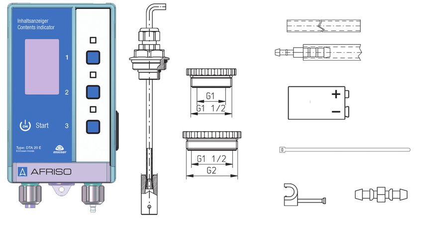
Transport und Lagerung                                    DE

2.5    Persönliche Schutzausrüstung
       Verwenden Sie immer die erforderliche persönliche Schutzausrüstung.
       Berücksichtigen Sie bei Arbeiten an und mit dem Produkt auch, dass am Ein-
       satzort Gefährdungen auftreten können, die nicht direkt vom Produkt ausge-
       hen.

2.6    Veränderungen am Produkt
       Führen Sie ausschließlich solche Arbeiten an und mit dem Produkt durch, die
       in dieser Betriebsanleitung beschrieben sind. Nehmen Sie keine Verände-
       rungen vor, die in dieser Betriebsanleitung nicht beschrieben sind.

3      Transport und Lagerung
       Das Produkt kann durch unsachgemäßen Transport und Lagerung beschä-
       digt werden.

                                     HINWEIS
    UNSACHGEMÄSSE HANDHABUNG
    • Stellen Sie sicher, dass während des Transports und der Lagerung des Pro-
      dukts die spezifizierten Umgebungsbedingungen eingehalten werden.
    • Benutzen Sie für den Transport die Originalverpackung.
    • Lagern Sie das Produkt nur in trockener, sauberer Umgebung.
    • Stellen Sie sicher, dass das Produkt bei Transport und Lagerung stoßge-
      schützt ist.
    Nichtbeachtung dieser Anweisungen kann zu Sachschäden führen.

                                                              DTA 20 E           5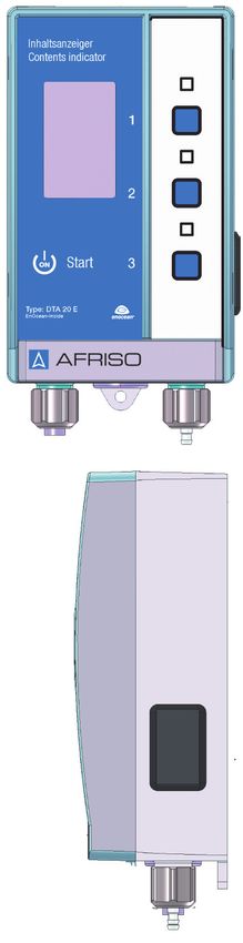
Produktbeschreibung                                    DE

4     Produktbeschreibung
4.1   Übersicht
      Das Produkt besteht aus einem Auswertegerät und einer Messleitung. Das
      Auswertegerät enthält in einem schlagfesten Kunststoffgehäuse das Display
      und die Bedienelemente.

                                     A      A. Digitales Display
                                            B. Keine Funktion
                                 B
                                            C. Obere Taste 1 (Ende/Einstellun-
                                     C         gen)
                                 D          D. Keine Funktion
                                     E      E. Mittlere Taste 2 (Info/Parameter)
                                 F          F. Keine Funktion
                                     G      G. Untere Taste 3 (Start)
                                            H. Anschluss für Messleitung
                                            I. Blindstopfen
                                            J. Batteriefach (für 9V-Blockbatte-
                                               rie)
                                     H
                                 I

                                     J

                                                              DTA 20 E            6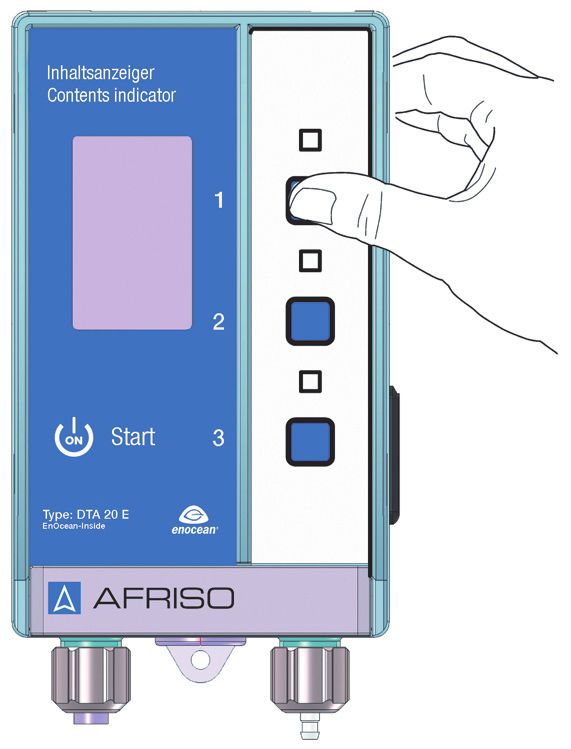
Produktbeschreibung              DE

Abmessungen
                                           65 mm
                      100 mm              60 mm
          166 mm
 188 mm

                                         DTA 20 E   7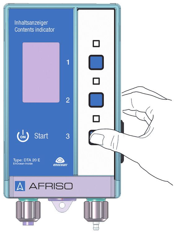
Produktbeschreibung DE
4.2 Lieferumfang
D
E
F
G
C
A B H I
A. Auswertegerät F. 9V-Blockbatterie
B. Messleitung (20 m) mit Fußteil G. Kabelbinder (2 Stück)
C. Verschraubungsset H. Nagelschelle (30 Stück)
G1½ a x G1 i, G2 a x G1½ i I. Schlauchadapter
D. PVC-Schlauch (100 cm)
E. PVC-Schlauch (15 cm) mit
Zubehör-Beutel (ohne Abbildung) mit
Schlauchverbinder (zum zwei Schrauben und zwei Dübeln für
Anschluss an Metallleitungen) Wandbefestigung
DTA 20 E 8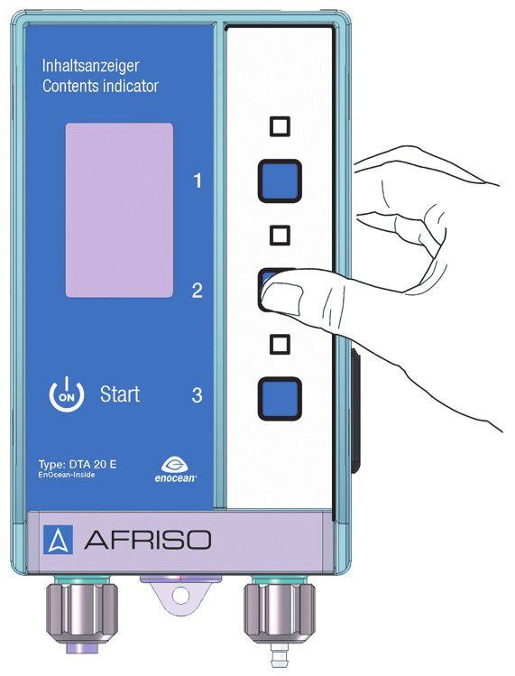
Produktbeschreibung                                       DE

4.3   Anwendungsbeispiel

4.4   Funktion
      Das Produkt besteht aus einem Auswertegerät mit digitaler Anzeige. Am
      Auswertegerät sind folgende Eingaben möglich:
      •   Sprache (Deutsch, Englisch, Französisch, Polnisch, Italienisch, Spa-
          nisch)
      •   Kontrast (in Prozent)
      •   Werkseinstellung
      •   Messintervall (in Stunden)
      •   Funk lernen (Lerntelegramm zum Einlernen am Gateway)
      •   Medium (Heizöl, Wasser und Variabel)
      •   Tankform (Linear, Kugel und liegender Zylinder)
      •   Füllhöhe bei 100 % (in cm)
      •   Volumen (in Liter)
      •   Alarm (in Prozent)
      Wenn die untere Taste gedrückt wird oder der Zeitpunkt des eingestellten
      Messintervalls erreicht ist, misst das Produkt den Füllstand im Tank.

                                                             DTA 20 E            9
Produktbeschreibung DE
Wenn während einer Messung der eingestellte prozentuale Minimalfüllstand
unterschritten wird, erfolgt eine optische Alarmierung. Hierbei blinkt die Hin-
tergrundbeleuchtung des Displays rot.
Das Produkt sendet die Messergebnisse über das integrierte EnOcean®-
Funkmodul an das AFRISOhome Gateway.
4.5 Zulassungsdokumente, Bescheinigungen, Erklärungen
Das Produkt entspricht:
• EMV-Richtlinie (2014/30/EU)
• Niederspannungsrichtlinie (2014/35/EU)
• Radio Equipment Directive, RED (2014/53/EU)
• RoHS-Richtlinie (2011/65/EU)
DTA 20 E 10Produktbeschreibung DE
4.6 Technische Daten
Parameter Wert
Allgemeine Daten
Abmessungen Gehäuse (B x H x T) 100 x 188 x 65 mm
Messleitung PVC-Schlauch 4 x 1 mm
Länge 20 m
Fußteil Edelstahl
Werkstoff Gehäuse Wandaufbaugehäuse aus schlag-
festem Kunststoff (ABS)
Messgenauigkeit ±3,0 cm (Mediumsäule)
Funktion Push-To-Read Füllstandmessung
Display Mehrfarbiges, graphisches Display
(30 x 50 mm) mit Hintergrundbe-
leuchtung
- Weiß = Betrieb
- Rot = Alarm
- Grün = Parametrierung
Volumen-Anzeige in Liter (5-stellig),
in % und Füllhöhe in cm
Umgebungsbedingungen
Umgebungstemperatur Betrieb 0 ... 50 °C
Umgebungstemperatur Lagerung -20 ... 65 °C
Mediumstemperatur 0 ... 50 °C
Elektrische Daten
Spannungsversorgung 9V-Blockbatterie,
ZnC (Zink-Kohle)
Lebensdauer Batterie 2 Jahre
(bei Messintervall von 24 Std.)
Schutzart (EN 60529) IP 20
Messbereich (Tankhöhe)
Heizöl Max. 4,0 m
Wasser Max. 3,5 m
Variabel abhängig von der Dichte
DTA 20 E 11Produktbeschreibung DE
Parameter Wert
EnOcean®-Funk
Frequenz 868,3 MHz
Sendeleistung Max. 10 mW
Reichweite Siehe Kapitel "Informationen zu EnO-
cean®-Funk"
EnOcean® Equipment Profile Generic Profile (GP)
(EEP)
DTA 20 E 12Montage DE
5 Montage
5.1 Montage vorbereiten
5.1.1 Produkt mit AFRISOhome Gateway verbinden
Der Einlernvorgang ist in der Betriebsanleitung des AFRISOhome Gate-
ways oder der App beschrieben.
Stellen Sie sicher, dass eine Batterie eingelegt ist (siehe Kapitel "Elek-
trischer Anschluss").
Stellen Sie sicher, dass sich das AFRISOhome Gateway in der Nähe
des Produkts befindet.
Stellen Sie sicher, dass sich das AFRISOhome Gateway im „Einlern-
Modus“ befindet.
1. Drücken Sie die untere Taste um
das Produkt einzuschalten.
- Das Produkt startet eine Mes-
sung automatisch.
- Das Display zeigt die Sprach-
auswahl (siehe "Sprache aus-
wählen").
2. Drücken Sie die mittlere Taste
4 x, bis das Menü „Funk Lernen“
angezeigt wird.
3. Drücken Sie die obere Taste 1 x.
- Das Produkt sendet ein Lern-
Telegramm (LRNTEL).
- Das Produkt ist mit dem AFRI-
SOhome Gateway verbunden.
DTA 20 E 13Montage DE
5.2 Produkt montieren
Befestigen Sie das Auswertegerät an der Wand. Verwenden Sie je nach
Untergrund die mitgelieferten Dübel.
Stellen Sie sicher, dass das Auswertegerät an eine ebene, feste und tro-
ckene Wand in Augenhöhe montiert ist.
Stellen Sie sicher, dass das Auswertegerät jederzeit zugänglich und ein-
sehbar ist.
Stellen Sie sicher, dass das Auswertegerät vor Wasser und Spritzwasser
geschützt ist.
Stellen Sie sicher, dass die Umgebungsbedingungen eingehalten wer-
den.
2 1. Befestigen Sie die obere
Schraube an der Wand.
1 2. Hängen Sie das Auswertegerät
ein.
3. Richten Sie das Auswertegerät
aus.
4. Befestigen Sie das Auswertegerät
an der Wand mit einer Schraube
an der unteren Lasche.
3
DTA 20 E 14Montage DE
5.3 Elektrischer Anschluss
HINWEIS
ELEKTROSTATISCHE ENTLADUNG
• Erden Sie sich immer, bevor Sie die elektronischen Bauteile berühren.
Nichtbeachtung dieser Anweisungen kann zu Sachschäden führen.
HINWEIS
UNSACHGEMÄSSE HANDHABUNG
Das Produkt darf nur seitlich am Batteriefach geöffnet werden.
• Öffnen Sie das Produkt nur, um die 9V-Blockbatterie einzulegen oder zu
wechseln.
Nichtbeachtung dieser Anweisungen kann zu Sachschäden führen.
DTA 20 E 15Montage DE
5.3.1 Batterie einsetzen/anschließen
Die 9V-Blockbatterie ist werksseitig nicht in das Auswertegerät einge-
setzt. Die Blockbatterie befindet sich im Zubehörbeutel.
1. Öffnen Sie mit einem Schlitz-
schraubendreher den Deckel des
Batteriefachs.
2. Schließen Sie die 9V-Blockbatte-
rie an.
3. Schieben Sie die 9V-Blockbatterie
in das Batteriefach (Einbaulage
beachten).
4. Schließen Sie den Deckel des
Batteriefachs.
DTA 20 E 16Montage DE
5.4 Messleitung am Tank montieren
HINWEIS
FALSCHE MESSERGEBNISSE
• Stellen Sie sicher, dass die Messleitung nicht geknickt oder beschädigt wird.
Nichtbeachtung dieser Anweisungen kann zu Sachschäden führen.
A 1. Wählen Sie zum Tankanschluss
den passenden Gewindeadapter
(Verschraubungsset).
B
A. Verschraubung zur Fixierung der
Messleitung
C B. Anschlussgewinde (G½ und G1)
C. Gewindeadapter (G1 auf G1½)
D. Gewindeadapter (G1½ auf G2)
D
E. Fußteil
E
F 1. Lassen Sie das Fußteil (H) bis auf
den Tankboden herunter.
G 2. Ziehen Sie die Verschraubung (F)
so fest, dass sich die Messleitung
nicht mehr verschieben lässt.
3. Befestigen Sie, falls nötig, die
Messleitung (G) mit den beigeleg-
H ten Nagelschellen.
DTA 20 E 17Montage DE
5.5 Messleitung am Auswertegerät montieren
A
B
1. Kürzen Sie die Messleitung (B) auf die gewünschte Länge.
2. Ziehen Sie die Messleitung (B) über den Schlauchadapter (A) am Aus-
wertegerät.
3. Befestigen Sie die Messleitung (B) mit einem Kabelbinder am Schlauch-
adapter (A).
Die Montage an bauseits bereits verlegte Messleitungen (Metallrohre) eines
ehemaligen pneumatischen Tankinhaltsanzeigers (beispielsweise Unitop/
Unitel) ist mit den beiden beigelegten Kabelbindern möglich.
Wenn Sie eine vorhandene Messleitung nutzen, stellen Sie sicher, dass die
Messleitung bis zum Tankboden reicht.
Die Messleitung (PVC) kann bei Kontakt mit Heizöl mit der Zeit hart werden.
Eine Verhärtung der Messleitung beeinträchtigt die Funktion des Produkts
nicht.
DTA 20 E 18Montage DE
5.6 Montageset Batterietanks „Pneum.“ montieren (optional)
Batterietanks verfügen, je nach Hersteller, über einen oder mehrere Kunst-
stoffflansche (A). Diese Kunststoffflansche sind für die Befüllung, Entlüftung
oder Entnahme vorgesehen.
Das Montageset wird an einem der Kunststoffflansche (A) eingebaut.
A A. Kunststoffflansch
A. Anschlussstutzen mit
A
konischem Gewinde
B. Schlauch
C. Gewicht Ø 9 mm
B
C
1. Prüfen Sie, ob der Kunststoffflansch des Batterietanks über eine mit
einem Blindstopfen verschlossenen Bohrung Ø 10 mm bis Ø 10,5 mm
verfügt.
2. Entfernen Sie den Blindstopfen.
DTA 20 E 19Inbetriebnahme DE
3. Schieben Sie das Gewicht (C) und den Schlauch (B) durch die Bohrung.
4. Schrauben Sie den Anschlussstutzen (A) in die Bohrung.
Wenn der Kunststoffflansch keine Bohrung hat, gehen Sie wie folgt vor:
1. Bauen Sie den Kunststoffflansch aus.
2. Bohren Sie senkrecht durch den Kunststoffflansch ein Loch Ø 10 mm.
3. Bauen Sie den Kunststoffflansch wieder ein.
4. Schieben Sie das Gewicht (C) und den Schlauch (B) durch die Boh-
rung.
5. Schrauben Sie den Anschlussstutzen (A) in die Bohrung.
6 Inbetriebnahme
6.1 Produkt in Betrieb nehmen
Stellen Sie sicher, dass alle Voraussetzungen für den Betrieb des Pro-
dukts erfüllt sind.
Beim ersten Einschalten:
1. Drücken Sie die untere Taste um
das Produkt einzuschalten.
- Das Produkt startet eine Mes-
sung automatisch.
- Das Display zeigt die Sprach-
auswahl (siehe "Sprache aus-
wählen").
2. Drücken Sie die obere oder untere
Taste, um die gewünschten Spra-
che einzustellen.
3. Drücken Sie die mittlere
Taste 1 x.
- Die eingestellte Sprache wird
übernommen und das Display
wechselt in die nächste Menü-
einstellung.
DTA 20 E 20Inbetriebnahme DE
6.1.1 Sprache auswählen
Sie können aus folgenden Sprachen wählen:
• Deutsch
• Englisch
• Französisch
• Polnisch
• Italienisch
• Spanisch
6.2 Produkt parametrieren
Für die Parametrierung stehen drei Tasten zur Verfügung. Das Display zeigt
an, welcher Menüpunkt bearbeitet wird. Die Menüpunkte sind nacheinander
beschrieben.
Display Übersicht
A A. Aktueller Menüpunkt
B B. Eingestellter Wert
C. Einstellbereich
D. Wert erhöhen (Taste 1)
C
E. Wert übernehmen (Taste 2)
D
F. Wert verringern (Taste 3)
E
F
1. Drücken Sie die mittlere Taste 1 x.
6.2.1 Sprache wechseln
1. Halten Sie die obere Taste so lange gedrückt, bis das Produkt zur
Sprachauswahl wechselt.
2. Drücken Sie die obere oder untere Taste, um die gewünschten Spra-
che einzustellen.
3. Wechseln Sie in den nächsten Menüpunkt.
DTA 20 E 21Inbetriebnahme DE
6.2.2 Kontrast einstellen
Sie können folgende Werte wählen:
• 0 % - 100 %
Der Kontrast kann in Schritten von 5 % verändert werden.
Werkseinstellung: 35 %
6.2.3 Auf Werkseinstellung setzen
1. Halten Sie die obere Taste so
lange gedrückt, bis das Produkt
zur Sprachauswahl wechselt.
2. Drücken Sie die mittlere Taste
2 x.
A - Das Produkt wechselt zum
Menü Werkseinstellung.
3. Halten Sie die obere Taste so
lange gedrückt, bis das Wort
„Reset“ (A) im Display steht.
- Ein Countdown von 5 Sekunden
wird im Display herunter gezählt.
6.2.4 Messintervall einstellen
Sie können folgende Werte wählen:
• AUS
• 1 - 240 Stunden
Aus den Einzelwerten des Messintervalls (24 Stunden) lässt sich der Ver-
lauf des Füllstands in der AFRISOhome Smart Home App visualisieren.
Ein längeres Messintervall einstellen (beispielsweise 48 Stunden):
1. Drücken Sie die obere oder untere Taste (Einzelschritte) oder halten
Sie die jeweilige Taste so lange gedrückt, bis Sie das gewünschte
Messintervall eingestellt haben.
Werksseitig ist das Messintervall auf 24 Stunden eingestellt. Ein erhöhtes
Messintervall kann die Lebensdauer der Batterie verkürzen.
6.2.5 Funk lernen
Sie können das Produkt mit dem AFRISOhome Gateway verbinden
(siehe "Produkt mit AFRISOhome Gateway verbinden").
DTA 20 E 22Inbetriebnahme DE
6.2.6 Medium einstellen
Sie können folgende Medien wählen:
• Wasser (Dichte 1 g/cm³)
• Heizöl (Dichte 0,84 g/cm³)
• Variabel (Dichte einstellbar von 0,5 - 1,5 g/cm³)
Je nach gewähltem Medium werden im Display die Einstellbereiche für
die Füllhöhe angezeigt.
6.2.7 Tankformen einstellen
Wenn die Geometrie des Tanks von den genannten Tankformen
abweicht, sind die Angaben aus der Peiltabelle des Tankherstellers zu
entnehmen.
Sie können folgende Tankformen wählen:
• Linear
• Kugel
• Liegender Zylinder
6.2.8 Durchmesser
Wenn die Tankform Kugel oder liegender Zylinder gewählt wurde, öffnet
sich das Menü „Durchmesser“.
Sie können folgende Werte wählen:
• Kugel: 0 - 576 cm
• Liegender Zylinder: 0 - 800 cm
6.2.9 Füllhöhe einstellen
Die Füllhöhe ist abhängig vom eingegebenen Medium. Sie können fol-
gende Werte wählen:
• Wasser: 0 - 350 cm
• Heizöl: 0 - 416 cm
• Variabel: abhängig von der Dichte
Eine größere Füllhöhe einstellen (beispielsweise 450 cm):
1. Drücken Sie die obere oder untere Taste (Einzelschritte) oder halten
Sie die jeweilige Taste so lange gedrückt, bis Sie die gewünschte Füll-
höhe eingestellt haben.
DTA 20 E 23Inbetriebnahme DE
6.2.10 Tankvolumen einstellen
Sie können folgende Werte wählen:
• 0 - 99999 Liter
1. Drücken Sie die obere oder untere Taste (Einzelschritte) oder halten
Sie die jeweilige Taste so lange gedrückt, bis Sie das gewünschte
Tankvolumen eingestellt haben.
6.2.11 Alarm einstellen
Sie können folgende Werte wählen:
• AUS
• 0 % - 100 %
6.3 Parametrierung beenden
Der Menüpunkt Alarm ist der letzte Punkt in der Parametrierung.
1. Drücken Sie die mittlere Taste 1 x, um in den Betriebsmodus zu wech-
seln.
Ende (A)
A Produkt ausschalten / Einstellungen
ändern
1. Drücken Sie die obere Taste 1 x.
- Produkt ist ausgeschaltet.
B
2. Halten Sie die obere Taste
gedrückt.
- Das Display wechselt in das
C Parametermenü.
DTA 20 E 24Inbetriebnahme DE
Info (B)
Parameter prüfen
1. Drücken Sie die mittlere Taste 1 x.
- Die eingegebenen Werte werden angezeigt.
2. Drücken Sie die mittlere Taste 2 x.
- Der Batteriestatus und die Softwareinformationen des Produkts werden
angezeigt.
3. Halten Sie die mittlere Taste gedrückt.
- Das Display wechselt in das Parametermenü.
- Die eingegebenen Parameter können erneut geändert werden.
Start (C)
Messung starten.
DTA 20 E 25Betrieb DE
7 Betrieb
Wenn die untere Taste gedrückt wird oder der Zeitpunkt des eingestellten
Messintervalls erreicht ist, misst das Produkt den Füllstand im Tank. Die
Messergebnisse werden über das interne EnOcean®-Funkmodul an das
AFRISOhome Gateway übertragen.
7.1 Messung manuell starten
1. Drücken Sie die untere Taste um
das Produkt einzuschalten.
- Das Produkt startet eine Mes-
sung automatisch.
- Nach wenigen Sekunden wer-
den die Daten der Messung
angezeigt.
Wenn die Messleitung länger als 20 m ist, führen Sie eine zweite Messung
durch.
DTA 20 E 26Betrieb DE
7.2 Batteriestatus-/Softwareanzeige
1. Drücken Sie die mittlere Taste
2 x.
- Der Batteriestatus und die Soft-
wareinformationen des Produkts
werden angezeigt.
2. Drücken Sie die mittlere Taste
erneut 1 x.
- Das Display wechselt in die
Hauptanzeige.
7.3 Produkt ausschalten
1. Drücken Sie die obere Taste 1 x,
um das Produkt auszuschalten.
Wenn längere Zeit keine Taste
gedrückt wird, schaltet sich das Pro-
dukt automatisch aus.
DTA 20 E 27Wartung DE
8 Wartung
8.1 Wartungsintervalle
Zeitpunkt Tätigkeit
Einmal jährlich Führen Sie eine Sichtprüfung (Schlauch prüfen)
durch.
Tauschen Sie beschädigte Teile.
Bei Bedarf Batterie ersetzen
8.2 Wartungstätigkeiten
1. Gehen Sie vor wie in Kapitel "Batterie einsetzen/anschließen" beschrie-
ben.
- Die gespeicherten Einstellungen gehen bei einem Batteriewechsel nicht
verloren.
9 Störungsbeseitigung
Störungen, die nicht durch die im Kapitel beschriebenen Maßnahmen besei-
tigt werden können, dürfen nur durch den Hersteller behoben werden.
Problem Mögliche Ursache Fehlerbehebung
Display zeigt nichts an Blockbatterie (9 V) ist Setzen Sie eine neue
leer Blockbatterie (9 V) ein
Falsche Füllstandsan- Tankdaten falsch einge- Korrigieren Sie die
zeige geben Tankdaten (siehe Kapi-
tel "Produkt in Betrieb
Tankform falsch einge-
nehmen")
geben
Prüfen Sie die Messlei-
Messleitung reicht nicht
tung im Tank
bis zum Tankboden
Messleitung ist undicht
Sonstige Störungen - Bitte wenden Sie sich an
die AFRISO-Service
Hotline
DTA 20 E 28Außerbetriebnahme und Entsorgung DE
10 Außerbetriebnahme und Entsorgung
Entsorgen Sie das Produkt nach den geltenden Bestimmungen, Normen und
Sicherheitsvorschriften.
Elektronikteile und Batterien dürfen nicht mit dem Hausmüll entsorgt werden.
Stellen Sie sicher, dass die 9V-Blockbatterie vollständig entleert ist.
1. Entnehmen Sie die Batterie (siehe Kapitel "Batterie ein-
setzen/anschließen" in umgekehrter Reihenfolge).
2. Demontieren Sie das Produkt (siehe Kapitel "Montage"
in umgekehrter Reihenfolge).
3. Entsorgen Sie das Produkt und die Batterie getrennt.
11 Rücksendung
Vor einer Rücksendung Ihres Produkts müssen Sie sich mit uns in Verbin-
dung setzen (service@afriso.de).
12 Gewährleistung
Informationen zur Gewährleistung finden Sie in unseren Allgemeinen
Geschäftsbedingungen im Internet unter www.afriso.com oder in Ihrem Kauf-
vertrag.
DTA 20 E 29Ersatzteile und Zubehör DE
13 Ersatzteile und Zubehör
HINWEIS
UNGEEIGNETE TEILE
• Verwenden Sie nur Original Ersatz- und Zubehörteile des Herstellers.
Nichtbeachtung dieser Anweisung kann zu Sachschäden führen.
Produkt
Artikelbezeichnung Art.-Nr. Abbildung
Digitaler Tankinhaltsanzei- 52146
ger DTA 20 E mit Pneumo-
fix Typ 2
Digitaler Tankinhaltsanzei- 52156
ger DTA 20 E
Ersatzteile und Zubehör
Artikelbezeichnung Art.-Nr. Abbildung
Pneumofix Typ 2 20142 -
PVC-Schlauch 20696 -
Ø 4 x 1 mm, 20 m inkl.
Montagezubehör
Schlauchverbinder 43945 -
Reduzierstück G1½ x G1 20905 -
Reduzierstück G2 x G1½ 20903 -
Flanschadapter G1½ 20900 -
Kondensatgefäß KG 2 20320 -
Montageset Batterietanks 52154 -
„Pneum.“
DTA 20 E 30Informationen zu EnOcean®-Funk DE
14 Informationen zu EnOcean®-Funk
14.1 Reichweiten des EnOcean®-Funks
Weiterführende Informationen zur Reichweitenplanung mit EnOcean® fin-
den Sie auf www.enocean.com.
14.2 Weiterführende Informationen zu EnOcean®-Funksystemen
Weiterführende Informationen zu Planung, Installation und Betrieb von
EnOcean®-Funksystemen finden Sie auf www.enocean.com.
• Funkstandard
• Funktechnologie
• AN001
• AN102
• AN103
14.3 Möglichkeiten der EnOcean®-Technologie
Unterlagen über EnOcean®-Technologien finden Sie im Internet unter
www.afrisohome.de.
Auf unserem YouTube-Channel finden Sie eine Reihe von Videos zu
AFRISO-Produkten.
DTA 20 E 31Anhang DE
15 Anhang
15.1 EU-Konformitätserklärung
DTA 20 E 32Operating
instructions
Digital tank contents indicator
DTA 20 E
Copyright 2022 AFRISO-EURO-INDEX GmbH. All rights reserved.
Lindenstraße 20
74363 Güglingen
Telephone +49 7135 102-0
Service +49 7135 102-211
Telefax +49 7135 102-147
info@afriso.com
www.afriso.com
Version: 01.2022.0
ID: 900.000.0900About these operating instructions EN
1 About these operating instructions
These operating instructions describe the digital tank contents indicator
"DTA 20 E" (also referred to as "product" in these operating instructions).
These operating instructions are part of the product.
• You may only use the product if you have fully read and understood these
operating instructions.
• Verify that these operating instructions are always accessible for any type
of work performed on or with the product.
• Pass these operating instructions as well as all other product-related doc-
uments on to all owners of the product.
• If you feel that these operating instructions contain errors, inconsisten-
cies, ambiguities or other issues, contact the manufacturer prior to using
the product.
These operating instructions are protected by copyright and may only be
used as provided for by the corresponding copyright legislation. We reserve
the right to modifications.
The manufacturer shall not be liable in any form whatsoever for direct or con-
sequential damage resulting from failure to observe these operating instruc-
tions or from failure to comply with directives, regulations and standards and
any other statutory requirements applicable at the installation site of the prod-
uct.
DTA 20 E 2Information on safety EN
2 Information on safety
2.1 Safety messages and hazard categories
These operating instructions contain safety messages to alert you to poten-
tial hazards and risks. In addition to the instructions provided in these oper-
ating instructions, you must comply with all directives, standards and safety
regulations applicable at the installation site of the product. Verify that you are
familiar with all directives, standards and safety regulations and ensure com-
pliance with them prior to using the product.
Safety messages in these operating instructions are highlighted with warning
symbols and warning words. Depending on the severity of a hazard, the
safety messages are classified according to different hazard categories.
NOTICE
NOTICE indicates a hazardous situation, which, if not avoided, can result in
equipment damage.
2.2 Intended use
This product may only be used for measuring the level of the following liquids:
• Fuel oil (density 0.84 g/cm³)
• Water (density 1 g/cm³)
• Carburants paraffiniques HVO (~0.78 g/cm³) and GTL (~0.76 g/cm³)
• Variable (density adjustable from 0.5 - 1.5 g/cm³)
Any use other than the application explicitly permitted in these operating
instructions is not permitted and causes hazards.
Verify that the product is suitable for the application planned by you prior to
using the product. In doing so, take into account at least the following:
• All directives, standards and safety regulations applicable at the installa-
tion site of the product
• All conditions and data specified for the product
• The conditions of the planned application
DTA 20 E 3Information on safety EN
In addition, perform a risk assessment in view of the planned application,
according to an approved risk assessment method, and implement the
appropriate safety measures, based on the results of the risk assessment.
Take into account the consequences of installing or integrating the product
into a system or a plant.
When using the product, perform all work and all other activities in conjunc-
tion with the product in compliance with the conditions specified in the oper-
ating instructions and on the nameplate, as well as with all directives, stand-
ards and safety regulations applicable at the installation site of the product.
2.3 Predictable incorrect application
The product must never be used in the following cases and for the following
purposes:
• Hazardous area (EX)
- If the product is operated in hazardous areas, sparks may cause defla-
grations, fires or explosions
• Use as safety-related equipment
- The product does not replace the function of a level sensor at the fuel
oil tank
• Use with corrosive liquids
• Use as overfill prevention system
• Use for billing purposes (the product is not officially calibrated)
• In conjunction with products which are used for health-saving or life-sav-
ing purposes or whose operation may incur hazards to humans, animals
or property
2.4 Qualification of personnel
Only appropriately trained persons who are familiar with and understand the
contents of these operating instructions and all other pertinent product docu-
mentation are authorized to work on and with this product.
These persons must have sufficient technical training, knowledge and expe-
rience and be able to foresee and detect potential hazards that may be
caused by using the product.
All persons working on and with the product must be fully familiar with all
directives, standards and safety regulations that must be observed for per-
forming such work.
DTA 20 E 4Transport and storage EN
2.5 Personal protective equipment
Always wear the required personal protective equipment. When performing
work on and with the product, take into account that hazards may be present
at the installation site which do not directly result from the product itself.
2.6 Modifications to the product
Only perform work on and with the product which is explicitly described in
these operating instructions. Do not make any modifications to the product
which are not described in these operating instructions.
3 Transport and storage
The product may be damaged as a result of improper transport or storage.
NOTICE
INCORRECT HANDLING
• Verify compliance with the specified ambient conditions during transport or
storage of the product.
• Use the original packaging when transporting the product.
• Store the product in a clean and dry environment.
• Verify that the product is protected against shocks and impact during trans-
port and storage.
Failure to follow these instructions can result in equipment damage.
DTA 20 E 5Product description EN
4 Product description
4.1 Overview
The product consists of a control unit and a measuring line. The control unit
contains the display and the controls in an impact-resistant plastic housing.
A A. Digital display
B. No function
B
C. Upper key 1 (End/Settings)
C
D. No function
D
E. Centre key 2 (Info/Parameters)
E
F. No function
F
G. Lower key 3 (Start)
G
H. Connection for measuring line
I. Blind plug
J. Battery compartment (for 9 V
monobloc battery)
H
I
J
DTA 20 E 6Product description EN
Dimensions
65 mm
100 mm 60 mm
166 mm
188 mm
DTA 20 E 7Product description EN
4.2 Scope of delivery
D
E
F
G
C
A B H I
A. Control unit F. 9 V monobloc battery
B. Measuring line (20 m) with bottom G. Cable tie (2 pieces)
part
H. Nail cable clips (30 pieces)
C. Screw connector kit I. Hose adapter
G1½ male x G1 female,
G2 a x G1½ female
D. PVC hose (100 cm) Bag of accessories (not shown) with
two screws and two dowels for wall
E. PVC hose (15 cm) with hose con- mounting
nector (for connection to metal
pipes)
DTA 20 E 8Product description EN
4.3 Application example
4.4 Function
The product consists of a control unit with digital display. The following set-
tings can be made at the control unit:
• Language (German, English, French, Polish, Italian, Spanish)
• Contrast (percentage)
• Factory setting
• Measuring interval (in hours)
• Establish wireless connection (learn telegram to gateway)
• Medium (fuel oil, water and variable)
• Tank shape (linear, spherical and cylindrical horizontal)
• Liquid level at 100 % (in cm)
• Volume (in litres)
• Alarm (percentage)
DTA 20 E 9Product description EN
When the lower key is pressed or the adjusted measuring interval has been
reached, the product measures the level in the tank.
If during a measurement, the level is below the adjusted minimum level a
visual alarm is triggered. The backlight of the display flashes red.
The product sends the measurement results to the AFRISOhome Gateway
via the integrated EnOcean® wireless module.
4.5 Approvals, conformities, certifications
The product complies with:
• EMC Directive (2014/30/EU)
• Low Voltage Directive (2014/35/EU)
• Radio Equipment Directive, RED (2014/53/EU)
• RoHS Directive (2011/65/EU)
4.6 Technical data
Parameter Value
General specifications
Dimensions housing (W x H x D) 100 x 188 x 65 mm
Measuring line PVC hose 4 x 1 mm
Length 20 m
Bottom part stainless steel
Housing material Wall mounting housing made of
impact-resistant plastic (ABS)
Measuring accuracy ± 3.0 cm (liquid column)
Function Push-to-Read level measurement
Display Multi-coloured, backlit graphical dis-
play (30 x 50 mm)
- White = Operation
- Red = Alarm
- Green = Parameterisation
Volume indication in litres (5 digits),
in % and liquid level in cm
DTA 20 E 10Product description EN
Parameter Value
Ambient conditions
Ambient temperature operation 0 ... 50 °C
Ambient temperature storage -20 ... 65 °C
Temperature of the medium 0 ... 50 °C
Electrical data
Supply voltage 9 V monobloc battery,
ZnC
Service life of battery 2 years
(with a measuring interval of
24 hours)
Degree of protection (EN 60529) IP 20
Measuring range (tank height)
Fuel oil Max. 4.0 m
Water Max. 3.5 m
Variable Depends on density
EnOcean® wireless
Frequency 868.3 MHz
Transmission power Max. 10 mW
Range See chapter "Information on
EnOcean® wireless"
EnOcean® Equipment Profile (EEP) Generic Profile (GP)
DTA 20 E 11Mounting EN
5 Mounting
5.1 Preparing mounting
5.1.1 Connecting the product to an AFRISOhome gateway
See the operating instructions of the AFRISOhome gateway or the app for
detailed information on establishing a wireless connection.
Verify that a battery is inserted (refer to chapter "Electrical connection").
Verify that AFRISOhome gateway is in the vicinity of the product.
Verify that the AFRISOhome gateway is in "Learn" mode.
1. Press the lower key to switch on
the product.
- The product automatically starts
a measurement.
- The display shows the lan-
guages selection (see "Selecting
the language").
2. Press the centre key 4 times, until
the menu "Radio Learn" is dis-
played.
3. Press the upper key 1 x.
- The product sends a Learn tele-
gram (LRNTEL).
- The product is now connected to
the AFRISOhome gateway.
DTA 20 E 12Mounting EN
5.2 Mounting the product
Mount the control unit to the wall. Use the enclosed dowels, depending on the
type of wall.
Verify that the control unit is mounted to an even, rigid and dry wall at eye
level.
Verify that the control unit is accessible and easy to oversee at all times.
Verify that the control unit is protected against water and splash water.
Verify compliance with the specified ambient conditions.
2 1. Mount the upper screw to the wall.
2. Fit the control unit.
1 3. Align the control unit.
4. Fasten the control unit by screw-
ing the bottom lug to the wall.
3
5.3 Electrical connection
NOTICE
ELECTROSTATIC DISCHARGE
• Always earth yourself before touching electronic components.
Failure to follow these instructions can result in equipment damage.
NOTICE
INCORRECT HANDLING
The product may only be opened at the side at the battery compartment.
• Only open the product to insert or replace the 9 V monobloc battery.
Failure to follow these instructions can result in equipment damage.
DTA 20 E 13Mounting EN
5.3.1 Inserting/connecting the battery
The 9 V monobloc battery is not factory-installed in the control unit. The
monobloc battery is contained in the bag of accessories.
1. Open the cover of the battery
compartment using a slotted
screwdriver.
2. Connect the 9 V monobloc bat-
tery.
3. Push the 9 V monobloc battery
into the battery compartment (ver-
ify correct mounting position).
4. Close the cover of the battery
compartment.
DTA 20 E 14Mounting EN
5.4 Mounting the measuring line to the tank
NOTICE
INCORRECT MEASUREMENT RESULTS
• Verify that the measuring line is not bent or damaged.
Failure to follow these instructions can result in equipment damage.
A 1. Select the threaded adapter
(screw connector kit) suitable for
the tank connection.
B
A. Screw connector for holding the
measuring line
C B. Connection thread (G½ and G1)
C. Threaded adapter (G1 to G1½)
D. Threaded adapter (G1½ to G2)
D
E. Bottom part
E
F 1. Lower the bottom part (H) to the
bottom of the tank.
G 2. Tighten the screw connection (F)
so that the measuring line can no
longer be moved.
3. Use the enclosed nail cable clips
to fasten the measuring line (G), if
H necessary.
DTA 20 E 15Mounting EN
5.5 Mounting the measuring line to the control unit
A
B
1. Shorten the measuring line (B) to the required length.
2. Pull the measuring line (B) over the hose adapter (A) at the control unit.
3. Fasten the measuring line (B) with a cable tie to the hose adapter (A).
It is possible to connect the product to existing measuring lines (metal pipes)
of a decommissioned pneumatic tank contents indicator (for example, Uni-
top/Unitel) using the two enclosed cables ties.
If you use an existing measuring line, verify that the measuring line extends
all the way to the bottom tank bottom.
The measuring line (PVC) may harden over time if it is in contact with fuel oil.
Hardening of the measuring line does not interfere with the operation of the
product.
DTA 20 E 16Mounting EN
5.6 Mounting the mounting kit for battery tanks "Pneum." (optional)
Depending on the manufacturer, battery tanks have one or more plastic
flanges (A). The plastic flanges are provided for filling, venting or withdrawal.
The mounting kit is installed in one of the plastic flanges (A).
A A. Plastic flange
A. Connection piece with
A
conical thread
B. Hose
C. Weight Ø 9 mm
B
C
1. Check whether the plastic flange of the battery tank has a hole Ø 10 mm
to Ø 10.5 mm which is closed by means of a blind plug.
2. Remove the blind plug.
3. Push the weight (C) and the hose (C) through the hole.
DTA 20 E 17Commissioning EN
4. Screw the connection piece (A) into the hole.
If the plastic flange does not have a hole, proceed as follows:
1. Dismount the plastic flange.
2. Drill a vertical hole Ø 10 mm through the plastic flange.
3. Remount the plastic flange.
4. Push the weight (C) and the hose (C) through the hole.
5. Screw the connection piece (A) into the hole.
6 Commissioning
6.1 Commissioning the product
Verify that all prerequisites for operation of the product are met.
Initial switching on:
1. Press the lower key to switch on
the product.
- The product automatically starts
a measurement.
- The display shows the lan-
guages selection (see "Selecting
the language").
2. Press the upper or the lower key
to set the required language.
3. Press the centre key 1 x.
- The selected language is set
and the display changes to the
next menu setting.
DTA 20 E 18Commissioning EN
6.1.1 Selecting the language
You can select one of the following languages:
• German
• English
• French
• Polish
• Italian
• Spanish
6.2 Parameterisation of the product
Three keys are available for parameterisation. The display show which menu
item is being edited. The menu items are described in succession.
Display overview
A A. Current menu item
B B. Set value
C. Adjustment range
D. Increase value (key 1)
C
E. Confirm value (key 2)
D
F. Reduce value (key 3)
E
F
1. Press the centre key 1 x.
6.2.1 Changing the language
1. Hold down the upper key until the product switches to the language
selection.
2. Press the upper or the lower key to set the required language.
3. Switch to the next menu item.
DTA 20 E 19Commissioning EN
6.2.2 Adjusting the contrast
You can select the following values:
• 0 % - 100 %
The contrast can be changed in increments of 5 %. Factory setting: 35 %
6.2.3 Resetting the product to the factory settings
1. Hold down the upper key until the
product switches to the language
selection.
2. Press the centre key 2 x.
- The product displays the menu
A factory setting.
3. Hold down the upper key until the
work "Reset" (A) is shown on the
display.
- A countdown of 5 seconds is
counted down on the display.
6.2.4 Setting the measuring interval
You can select the following values:
• OFF
• 1 - 240 hours
Based on the individual values of the measuring interval (24 hours), the
development of the level over time can be visualised in the AFRISOhome
smart home app.
Setting a longer measuring interval (for example, 48 hours):
1. Press the upper or lower key (individual steps) or hold down the corre-
sponding key until you have set the required measuring interval.
The product is factory-set to a measuring interval of 24 hours. A higher
measuring interval can decrease the service life of the battery.
6.2.5 Radio Learn
You can connect the product to the AFRISOhome gateway (see "Con-
necting the product to an AFRISOhome gateway").
DTA 20 E 20Commissioning EN
6.2.6 Adjusting the medium
You can select one of the following liquids:
• Water (density 1 g/cm³)
• Fuel oil (density 0.84 g/cm³)
• Variable (density adjustable from 0.5 - 1.5 g/cm³)
Depending on the selected medium, the display shows the adjustment
ranges for the liquid level.
6.2.7 Setting the tank shape
If the geometry of the tank differs from the geometries listed, the informa-
tion must be taken from the bearing chart of the tank manufacturer.
You can select one of the following tank shapes:
• Linear
• Ball
• Horizontal cylinder
6.2.8 Diameter
If you have selected the tank shapes ball or horizontal cylinder, the menu
"Diameter" opens.
You can select the following values:
• Ball: 0 - 576 cm
• Horizontal cylinder: 0 - 800 cm
6.2.9 Adjusting the liquid level
The level depends on the medium entered. You can select the following
values:
• Water: 0 - 350 cm
• Fuel oil: 0 - 416 cm
• Variable: Depends on density
Adjusting a higher liquid level (for example 450 cm):
1. Press the upper or lower key (individual steps) or hold down the corre-
sponding key until you have set the required liquid level.
DTA 20 E 21Commissioning EN
6.2.10 Adjusting the tank volume
You can select the following values:
• 0 - 99999 litres
1. Press the upper or lower key (individual steps) or hold down the corre-
sponding key until you have set the required tank volume.
6.2.11 Adjusting the alarm
You can select the following values:
• OFF
• 0 % - 100 %
DTA 20 E 22Commissioning EN
6.3 Terminating parameterisation
The menu item Alarm is the last point in the parameterisation.
1. Press the centre key 1 x to switch to the regular mode of operation.
End (A)
A Switching off the product / changing
settings
1. Press the upper key 1 x.
- Product is switched off.
B
2. Hold down the upper key.
- The display changes to the first
parameters menu.
C
Info (B)
Checking parameters
1. Press the centre key 1 x.
- The values entered are displayed.
2. Press the centre key 2 x.
- The battery status and software information are displayed.
3. Hold down the centre key.
- The display changes to the first parameters menu.
- The parameters entered can be changed again.
Start (C)
Starting a measurement.
DTA 20 E 23Operation EN
7 Operation
When the lower key is pressed or the adjusted measuring interval has been
reached, the product measures the level in the tank. The measurement
results are transmitted to the AFRISOhome gateway via the internal
EnOcean® wireless module.
7.1 Starting a measurement manually
1. Press the lower key to switch on
the product.
- The product automatically starts
a measurement.
- The measured values are dis-
played after a few seconds.
If the measuring line is longer than 20 m perform a second measurement.
DTA 20 E 24Operation EN
7.2 Battery status
1. Press the centre key 2 x.
- The battery status and software
information are displayed.
2. Press the centre key again 1 x.
- The display changes to normal
mode.
7.3 Switching off the product
1. Press the upper key 1 x to switch
off the product.
If no key is pressed for an extended
period of time, the product switches
off automatically.
DTA 20 E 25Maintenance EN
8 Maintenance
8.1 Maintenance intervals
When Activity
Once per year Perform a visual inspection (inspect hose)
Replace damaged parts.
If required Replace battery
8.2 Maintenance activities
1. Proceed as described in chapter "Inserting/connecting the battery".
- Stored settings are not lost when the battery is replaced.
9 Troubleshooting
Any malfunctions that cannot be removed by means of the measures
described in this chapter may only be repaired by the manufacturer.
Problem Possible reason Repair
Display does not show Monobloc battery (9 V) Insert a new monobloc
anything is empty battery (9 V)
Incorrect level indication Incorrect tank data Correct the tank data
entered (see
chapter "Commissionin
Incorrect tank shape
g the product")
entered
Check the measuring
Measuring line does not
line in the tank
reach down to the tank
bottom
Leak in measuring line
Other malfunctions - Contact the AFRISO
service hotline
DTA 20 E 26Decommissioning, disposal EN
10 Decommissioning, disposal
Dispose of the product in compliance with all applicable directives, standards
and safety regulations.
Electronic components and batteries must not be disposed of together with
the normal household waste.
2. Dismount the product (see chapter "Mounting", reverse
sequence of steps).
3. Dispose of the product and the battery separately.
11 Returning the device
Get in touch with us before returning your product (service@afriso.de).
12 Warranty
See our terms and conditions at www.afriso.com or your purchase contract
for information on warranty.
DTA 20 E 27Spare parts and accessories EN
13 Spare parts and accessories
NOTICE
UNSUITABLE PARTS
• Only use genuine spare parts and accessories provided by the manufac-
turer.
Failure to follow these instructions can result in equipment damage.
Product
Product designation Part no. Figure
Digital tank contents indica- 52146
tor DTA 20 E with Pneumo-
fix type 2
Digital tank contents indica- 52156
tor DTA 20 E
Spare parts and accessories
Product designation Part no. Figure
Pneumofix type 2 20142 -
PVC hose Ø 4 x 1 mm, 20696 -
20 m, with mounting acces-
sories
Hose connector 43945 -
Reducer G1½ x G1 20905 -
Reducer G2 x G1½ 20903 -
Flange adapter G1½ 20900 -
Condensate trap KG 2 20320 -
Mounting kit battery tanks 52154 -
"Pneum."
DTA 20 E 28Information on EnOcean® wireless EN
14 Information on EnOcean® wireless
14.1 Range of EnOcean® wireless
Visit www.enocean.com for further information on range planning with
EnOcean®.
14.2 Additional information on EnOcean® wireless systems
Additional information on planning, installation and operation of EnOcean®
wireless systems can be found at www.enocean.com.
• Wireless standard
• Wireless technology
• AN001
• AN102
• AN103
14.3 Features of the EnOcean® technology
Visit www.afrisohome.de for documents on EnOcean® technologies.
A variety of videos on AFRISO products can also be found on the AFRISO
YouTube channel.
DTA 20 E 29Appendix EN
15 Appendix
15.1 EU Declaration of Conformity
DTA 20 E 30Notice technique
Indicateur numérique de niveau de réservoir
DTA 20 E
Copyright 2022 AFRISO-EURO-INDEX GmbH. Tous droits réservés.
Lindenstraße 20
74363 Güglingen
Téléphone +49 7135 102-0
Service clientèle +49 7135 102-211
Téléfax +49 7135 102-147
info@afriso.com
www.afriso.com
Version: 01.2022.0
ID: 900.000.0900La présente notice technique FR
1 La présente notice technique
Cette notice technique contient la description de l'indicateur numérique de
niveau de réservoir DTA 20 E (dénommé ci-après "produit"). Cette notice
technique fait partie du produit.
• Utilisez le produit seulement après que vous aurez lu et compris intégra-
lement la notice technique.
• Assurez-vous que la notice technique est disponible en permanence pour
toutes les opérations relatives au produit.
• Transmettez la notice technique et toute la documentation relative au pro-
duit à tous les utilisateurs du produit.
• Si vous êtes d'avis que la notice technique contient des erreurs, des
contradictions ou des ambiguïtés, adressez-vous au fabricant avant d'uti-
liser le produit.
Cette notice technique est protégée au titre de la propriété intellectuelle ; elle
doit être utilisée exclusivement dans le cadre autorisé par la loi. Sous réserve
de modifications.
La responsabilité du fabricant ou la garantie ne pourra être engagée pour des
dommages ou dommages consécutifs résultant d'une inobservation de cette
notice technique ou des directives, règlements et normes en vigueur sur le
lieu d'installation du produit.
DTA 20 E 2Informations sur la sécurité FR
2 Informations sur la sécurité
2.1 Consignes de sécurité et classes de risques
Cette notice technique contient des consignes de sécurité destinées à attirer
l'attention sur les dangers et les risques. Outre les instructions contenues
dans cette notice technique, il faut vous assurer de l'observation de tous les
règlements, normes et consignes de sécurité en vigueur sur le lieu d'installa-
tion du produit. Avant d'utiliser le produit assurez-vous que tous les règle-
ments, normes et consignes de sécurité sont connus et respectés.
Dans cette notice technique les consignes de sécurité sont identifiables à
l'aide de symboles de mise en garde et de mots d'avertissement. En fonction
de la gravité du risque les consignes de sécurité sont réparties dans diffé-
rentes classes de risques.
AVIS
AVIS signale une situation potentiellement dangereuse qui, si elle n'est pas
évitée, peut entraîner un dommage matériel.
2.2 Usage normal
Ce produit est destiné exclusivement à la mesure du niveau des liquides sui-
vants :
• Fuel (densité 0,84 g/cm³)
• Eau (densité 1 g/cm³)
• Paraffinic fuels HVO (~0,78 g/cm³) et GTL (~0,76 g/cm³)
• Variable (densité réglable de 0,5 à 1,5 g/cm³)
Toute autre utilisation n'est pas conforme et cause des risques.
Avant d'utiliser le produit, assurez-vous que le produit est adapté à l'usage
que vous prévoyez. À cet effet, tenez compte au moins de ce qui suit :
• Tous les règlements, normes et consignes de sécurité sur le lieu d'instal-
lation
• Toutes les conditions et données spécifiées pour le produit
• Toutes les conditions d'application que vous prévoyez
DTA 20 E 3Informations sur la sécurité FR
En outre effectuez une évaluation des risques portant sur l'application
concrète que vous prévoyez à l'aide d'un procédé reconnu et prenez toutes
les mesures de sécurité nécessaires correspondant au résultat. Prenez
aussi en compte les conséquences possibles du montage ou de l'intégration
du produit dans un système ou une installation.
Pendant l'utilisation du produit effectuez toutes les opérations exclusivement
dans les conditions spécifiées dans cette notice technique et sur la plaque
signalétique, conformément aux données techniques spécifiées et en accord
avec tous les règlements, normes et consignes de sécurité en vigueur sur le
lieu d'installation.
2.3 Utilisation non conforme prévisible
Le produit ne doit, en particulier, pas être utilisé dans les cas suivants :
• Dans des zones à risque d'explosion
- En cas de service dans des zones à risque d'explosion, des étincelles
peuvent provoquer des déflagrations, des incendies ou des explosions
• Utilisation comme dispositif de sécurité
- Le produit ne remplace pas un limiteur de remplissage sur le réservoir
de fuel
• Utilisation avec des liquides corrosifs
• Utilisation comme dispositif limiteur de remplissage
• Utilisation à fin de facturation (le produit n'est pas étalonné)
• Utilisation en combinaison avec des produits qui sont utilisés à des fins
de la protection de la santé ou à des fins de sauvetage; utilisation en com-
binaison avec des appareils dont le fonctionnement peut entraîner des
dangers pour les êtres humains, des animaux ou des biens matériels
2.4 Qualification du personnel
Seul le personnel dûment qualifié est autorisé à travailler sur le produit et
avec celui-ci après qu'il aura connu et compris le contenu de cette notice
technique, ainsi que toute la documentation faisant partie du produit.
S'appuyant sur sa formation spécialisée, ses connaissances et ses expé-
riences, le personnel qualifié doit être en mesure de prévoir et reconnaître les
dangers qui peuvent être causés par l'utilisation du produit.
Tous les règlements, normes et consignes de sécurité en vigueur sur le lieu
d'installation doivent être connus du personnel qualifié travaillant sur le pro-
duit et avec celui-ci.
DTA 20 E 4Sie können auch lesen