CLIMA500 Temperature Controller for Heating Circuit - ganzheitliche energiekonzepte
←
→
Transkription von Seiteninhalten
Wenn Ihr Browser die Seite nicht korrekt rendert, bitte, lesen Sie den Inhalt der Seite unten
CLIMA500
Witterungsgeführter Heizungsregler
für Systeme mit wasserführenden
Kaminofen oder Holzkessel,
Pufferspeicher und gemischtem Heizkreis

                          Temperature Controller
                              for Heating Circuit

                      Seite 1 / 33        CLIMA500 Anleitung V3.0
1 Anlageschemen Plant’s Survey
1 2 3 4
5 6 7 8
9 10 11 12
13 14 15
Seite 2 / 33 CLIMA500 Anleitung V3.02 Einleitung
CLIMA500 ist ein witterungsgeführter Heizungsregler für Systeme mit wasserführenden Kaminofen oder Holzkessel,
Pufferspeicher und gemischtem Heizkreis. Zusätzlich kann CLIMA500 ein weiterer Wärmeerzeuger (z.B. NT-Kessel)
angefordert werden. Durch die Ermittlungen der verschiedenen Temperaturen, wird ein Anlageschema der folgenden
Beschreibung ausgewählt. Die Einstellung der einzelnen Parameter erfolgt über die Menüführung. Bei der Erst-
Inbetriebnahme ist die Stellung des Mischers auf “ZU”. Dieser stellt sich danach den ausgewählten Einstellung
automatisch ein. Das gleiche trifft bei Stromausfall ein.
Wichtige Merkmale von KLIMA500:
• Darstellung von Grafiken und Texten im beleuchteten Display
• Einfache Abfrage der aktuellen Messwerte
• Umfangreiche Einstellmenüs
• Menüsperre gegen unbeabsichtigtes Verstellen
Konformitätserklärung Ganzheitliche Energiekonzepte GmbH & Co. KG,
Angewandte Normen: Entwicklung, Produktion und Handel
Überaucher Straße 9/1, 78052 Villingen-Schwenningen
EN 60730-1 50081-1 Telefon: +49 07705 977 5803, Fax.: +49 7705 977 5804
EN 60730-1 A1 50081-2 E-Mail: info@ganzheitliche-energiekonzepte.de
Lieferumfang Technische Daten
1x KLIMA500 Netzspannung: 230 Vac
5x Schrauben + 8x Zugentlastungen Netzfrequenz: 50 Hz
2x Befestigungsschrauben Leistungsaufnahme: 2A
1x Auf- bzw. Unterputzkasten Leistung Relaisausgang: 5A 250 Vac
1x Blende Interne Sicherung: 3,15 A
1x Montage- und Bedienungsanleitung Schutzart: IP40
Sensoreingänge: Pt1000
Messbereich: -40°C bis 300°C
Installationsbedingungen und Verwendung Caratteristiche Meccaniche
Umgebungstemperatur bei Reglerbetrieb: 0°C...40°C Gehäuseausführung Kunststoff ABS
Umgebungstemperatur bei Transport/Lagerung: 0°C...60°C Einbaumöglichkeiten: Aufputz- oder Unterputzmontage
Luftfeuchtigkeit: 85% @25°C Abmessungen: 160mm x 90mm x 58mm
Anzeige Display: BackLight 128 x 64 dots
3 Installation
3.1 Montage
Vor Arbeiten am Gerät die Stromzuleitung abschalten und gegen Wiedereinschalten sichern! Spannungsfreiheit prüfen!
Der elektrische Anschluss darf nur durch eine Fachkraft unter Berücksichtigung der geltenden Vorschriften durchgeführt
werden. Der Regler darf nicht in Betrieb genommen werden, wenn es am Gehäuse sichtbare Schäden wie z.B. Risse gibt.
F F
HH HH PL Fig. 1 Komponenten
F F
CC CC CC CC CC CC CC CC
P
VV VV VV VV VV Cx8 V x5 H x2
• Installieren Sie den Regler ausschließlich in trockenen Räumen und unter Umgebungsbedingungen
• Den Auf- bzw. Unterputzkasten mit Schrauben an den Punkten F fixieren
• Die Kabelabdeckung P entfernen
• Leitungen abmanteln, in den Zugentlastungen C einführen und diese in den Vertiefungen CC einlegen
• Klemmen mit einem passenden Schraubendreher öffnen und Elektroanschluss am Regler vornehmen.
• Gehäuseoberteil wieder einlegen und mit den Schrauben H über die Fixierpunkte HH verschließen
• Die Kabel mittels der Abdeckung P mit den Schrauben V in den Löchern VV fixieren
• Blende PL anbringen
Seite 3 / 33 CLIMA500 Anleitung V3.03.2 Elektrischer Anschluss
Vor Arbeiten am Gerät die Stromzuleitung abschalten und gegen Wiedereinschalten sichern! Spannungsfreiheit prüfen! Der elektrische
Anschluss darf nur durch eine Fachkraft unter Berücksichtigung der geltenden Vorschriften durchgeführt werden. Der Regler darf nicht in
Betrieb genommen werden, wenn es am Gehäuse sichtbare Schäden wie z.B. Risse gibt. Kleinspannungsführende Leitungen wie
Temperaturfühlerleitungen sind getrennt von netzspannungsführenden Leitungen zu verlegen.
S1 S2 S3 S4 PT1000 Fühler
S5 PT1000 Fühler / Raumthermostat
P1 P2 P3 P4 Relaisausgang mit 230 V
1 2 3 4 5 6 7 8 9 10 11 12 13 P5 potentialfreier Kontakt
14 15 16 17 18 19 20 21 22 23
COM
N.O.
N.C.
LN Lo N Lo N Lo N Lo N
LINE
230 Vac P1 P2 P3 P4 P5 S1 S2 S3 S4 S5 Fig. 2 Elektrische Verbindungen
4 Installation der Temperaturfühler
Der Regler arbeitet mit Pt1000-Temperaturfühlern, mit einem Range von -40 °C bis 300°C (+/- 1°C) Bei einen Kurzschluss im Fühler
erscheint im Display “Short”. Bei unterbrochenen oder nicht angesteckten Fühler erscheint im Display “Open”. Welche Messwerte
angezeigt werden ist vom gewählten Programm, den angeschlossenen Fühlern und der jeweiligen Geräteausführung abhängig.
CASACALOR übernimmt keine Verantwortung für Schäden an Fühlern, wenn diese nicht im Range Bereich eingesetzt worden sind oder
durch falsche Kabelverlängerungen.
• Die Temperaturfühlerleitungen sind getrennt von netzspannungsführenden Leitungen zu verlegen.
• Die Fühlerleitungen können bei Bedarf mit einem Kabel von mindestens 1mm² auf maximal 30m verlängert werden. Achten Sie
darauf, dass hierbei keine Übergangswiderstände auftreten!
• Platzieren Sie die Fühler genau im zu messenden Bereich!
• Verwenden Sie nur den für das jeweilige Einsatzgebiet passenden Tauch-, Rohranlege- oder
• Flachanlegefühler mit dem entsprechend zulässigen Temperaturbereich.
4.1 Außenfühler/Raumthermostat
In den vorgesehenen Anlageschemen, kann auf den Steckplätzen 16-17 (S2) und 22-23 (S5) einen Pt1000-
Außenfühler oder einen Raumthermostat angeschlossen werden. Um den Außenfühler auszuwählen, muss der
Parameter ENA010 auf OFF gestellt werden. Um den Raumthermostat auszuwählen, muss der Parameter ENA010 auf
ON gestellt werden. Ist der Kontakt geschlossen, erscheint im Display “TA=Short”, ist der Kontakt offen, erschei im Display
“TA=OPEN”. Wird kein Raumthermostat benutzt, müssen die Steckplätze 22-23 gebrückt werden.
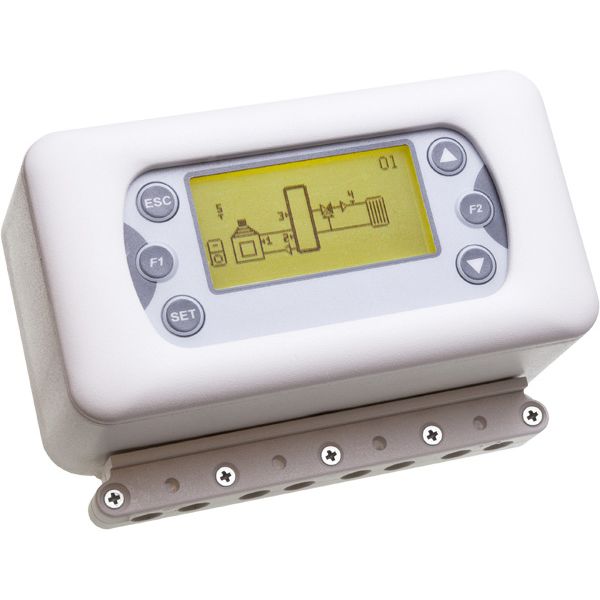
5 Bedienelement: Einsatz und Funktionen
Funktionen der Tasten:
P4/P6= Blättern im Menü - Wertzu- bzw. abnahme
P1 P4 P3= Betreten des Menüs - Speichern im Menü
P1= Verlassen des Menüs
P2 P5 P5= Aktivierung des Uhrenprogramm
P3 P6 Fig. 3 Bedienelement LCD
5.1 Display
Pumpe: Lun 10.30 Heizkessel:
ON wenn blinkt ON wenn blinkt
Mischer: Holzkessel:
Durchflussrichtung ON wenn blinkt
Funktion Nacht aktiv oder Auto aktive Meldungen
außerhalb Uhrenprogramms Modo Operativo
Funktion Tag aktiv
Solarkollektoren Heizkreislauf
oder während Uhrenprogramm
Funktion Sommer aktiv Funktion Winter aktiv E Dauer-Sommer aktiv
Fig. 4 Schermata Principale
Mit der Taste P4 gelangen Sie im Menu “Monitor” die gemessenen Temperaturen werden angezeigt.
Seite 4 / 33 CLIMA500 Anleitung V3.0Sys 1 = gew. Anlageschema Monitor Sys 1
Fühlertemperatur T1 = 10 T5 = 13
Fühlertemperatur T2 = 22 THC400=40 Berechneter Thermostat
Kontakt geschlossen T3 = Short
nicht Angeschlossen o. Kabelbruch T4 = Open
Fig. 5 Monitor Menu
Über die Taste P4 gelangen Sie in der Anzeige “Statistics” um die laufenden Fehlermeldungen zu entnehmen.
Sys 1 =gew. Anlageschema Statistics Sys 1
Fehlermeldungen
Fehlercode Ψ A02
Fig. 6 Statistics Menu
5.2 Meldungen
Beschreibung DISPLAY
Fühlertemperatur S4 höher als Thermostat THS405 - Zu hohe Vorlaufstemperatur A01
Fühlertemperatur Außenfühler (S1/S5) geringer als Thermostat THS103/THS503 - Zu niedrige Außentemperatur A02
Fühlertemperatur S1 (Holzkessel) höher als Thermostat THS104 A03
Fühlertemperatur S1 (Holzkessel) geringer als Thermostat THS102 - Zu niedrige Kesselemperatur A04
Fühlertemperatur S1 (Solarkollektor) hoher als Thermostat THS107 A05
Fühlertemperatur S2 (Puffer) höher als Thermostat THS203 A06
6 Menü
Das Menü ist wie folgt untergliedert:
Menü Fachmann: Hier können alle Einstellung für den Regler vorgenommen werden
Menü Endverbraucher: Hier werden nur die wichtigsten Einstellungen angezeigt
6.1 Menü Fachmann
Beinhaltet alle Thermostate und
Thermostate Hysteresen
Parameter Beinhaltet alle Parameter
Arbeitsweise
Modalität
Uhrenprogramm
Programmierung
Mixer
Außenfühler
Antifrost
Beinhaltet alle Funktionen die verwendet
Funktionen Sommer Winter werden können.
Raumthermostat
Antiblockiersystem Pumpe
Heizkessel
Holzkessel
Antilegionellen
Solar
Test Ausgänge Menü zum testen der Ausgänge
Datum und Uhrzeit Menü Einstellung Datum und Uhrzeit
Sprache Auswahl der Sprache
Initialisierung Re-Initialisierung des Systems
Password ändern Menü Password ändern
Endverbraucher Menü Endverbraucher Menü
Menü Bedienelement Menü Bedienelement LCD
Seite 5 / 33 CLIMA500 Anleitung V3.06.2 Erst-Inbetriebnahme
Bei der Erst-Inbetriebnahme muss CLIMA500 initialisiert und configuriert werden:
1
Der zur Verfügung stehende Das Anlageschema über die
Anlageschema wird angezeigt Taste P4 / P6 auswählen.
Das gewünschte Anlageschema über die
Taste P3 bestätigen.
Auto
Die gleiche Funktion ist im Menü Fachmann unter den Einsteller Initialisierung auswählbar.
6.3 Menü Fachmann
Main Menu PASSWORD? • Mit P3 wird die erste Zahl ausgewählt 0 - - -
Menü Fachmann • Mit P4 u. P6 wird der Wert gewählt 1---
• Mit P3 bestätigen Sie den Wert 10--
- - - - • Wiederholen Sie bis zur 4 Zahl 1234
• PASSWORD mit Taste P3 bestätigen
• Mit P1 werden die gesetzten Zahlen gelöscht
Wenn Sie über eine längere Zeit im Fachmann Menü keine Taste drücken, dann führt Sie das
System automatisch im Endverbrauchermenü.
6.4 Menü Thermostate
In dieser Ebene werden alle Thermostate und Hysteresen angezeigt.
6.5 Menü Parameter
In dieser Ebene werden alle Timer, aktive Zähler und Werte für den gewählten Anlageschema angezeigt.
6.6 Menü Funktionene
In dieser Ebene werden alle Funktionen angezeigt.
6.6.1 Menü Betriebsart
In dieser Ebene werden die Betriebsarten für den Mischer eingestelt.
Beschreibung Display
ENA004 Modalität Automatik
Der Thermostat THC400 auf dem Fühler S4 (Vorlauftemperatur) wird vollautomatisch über die folgenden
Werte ermittelt:
• Außentemperatur über S5
• ausgewählte Heizkurve: COU002
• Temperaturanpassung TAG: THS403
• Temperaturanpassung NACHT: THS404
• T-Confort: THS406 Auto
In particolare:
- Uhrenprogramm desaktiviert: THC400 = F(COU002 , S5) + THS406
- Temperaturanpassung TAG: THC400 = F(COU002 , S5) + THS403 + THS406
- Temperaturanpassung NACHT: THC400 = F(COU002 , S5) + THS404 + THS406
Der Regler stellt den Mischer über die errechnete Vorlauftemperatur ein (mit Berücksichtigung der eingestellten
Hysterese HYS400).
ENA005 Modalität TAG
Der Thermostat THC400 auf dem Fühler S4 (Vorlauftemperatur) wird automatisch über die folgenden Werte
ermittelt:
• Außentemperatur über S5 (Sonda esterna)
• ausgewählte Heizkurve: COU002
• Temperaturanpassung TAG: THS403
• T-Confort: THS406
Besonders: THC400 = F(COU002 , S5) + THS403 + THS406.
Der Regler stellt den Mischer über die errechnete Vorlauftemperatur ein (mit Berücksichtigung der eingestellten
Hysterese HYS400).
Seite 6 / 33 CLIMA500 Anleitung V3.0ENA006 Modalität NACHT
Der Thermostat THC400 auf dem Fühler S4 (Vorlauftemperatur) wird automatisch über die folgenden Werte
ermittelt:
• Außentemperatur über S5: COU002
• Temperaturanpassung Nacht THS404
• Temperaturanpassung Confort: THS406
Besonders: THC400 = F(COU002 , S5) + THS404 + THS406
Der Regler stellt den Mischer über die errechnete Vorlauftemperatur ein (mit Berücksichtigung der eingestellten
Hysterese HYS400).
ENA007 Modalität manueller Mischer
Der Thermostat THC400 wird ignoriert. Manueller
Die Stellung des Mischers kann manuell über die Tasten P2 und P5 geändert werden. Mischer
Bei jedem drücken der Taste P2 / P5, schließt oder öffnet sich der Mischer um einen Step.
ENA008 Modalität manueller Thermostat
THC400 = THS400: Der Thermostat THC400 auf dem Fühler S4 (Vorlauftemperatur) wird manuell über Manueller
den Thermostat THS400 eingestellt
Der Regler stellt den Mischer so ein, dass der Thermostat THC400 erreicht wird (mit Berücksichtigung Thermostat
der eingestellten Hysterese HYS400).
Kein Status aktiviert Modalität OFF
Die Regelung des Heizkreises ist ausgeschaltet
OFF
6.6.2 Menü Uhrenprogramm
Menü für die Einstellung des Uhrenprogramm mit Berücksichtigung der Temperaturanpassung TAG (THS403) für die
Berechnung vom Thermostatwert THC400. Außerhalb des Uhrenporgramm oder bei inaktiven Uhrenprogramm, wird für
die Berechnung des Thermostatwert THC400 immer die Temperaturaanpassung NACHT (THS404) verwendet.
6.6.2.1. Uhrenprogramm: Modalität
Ermöglicht eine der 4 Modalitäten auszuwählen
Uhrenprogramm Modalità
• Mit P3 die Einstellung ändern (Kursor blinkt)
Modalität Deaktiviert • Mit P4 und P6 den Wert auswählen
Programm Tag • Mit P3 den Wert bestätigen
Woche • Mit P1 die Ebene verlassen
Wochenende
6.6.2.2. Uhrenprogramm: Programmierung
Uhrenprogramm Programm • Mit P3 die Einstellung ändern (Kursor blinkt)
Modalität Tag • Mit P4 und P6 den Wert auswählen
Programm Woche • Mit P3 den Wert bestätigen
Parameter Wochenende • Mit P1 die Ebene verlassen
• Uhrenprogramm TAG: Für jeden einzelnen Wochentag werden 3 Zeitfenster angezeigt.
Programm Montag Montag
Tag Dienstag ON OFF
Mittwoch
Woche 09:30 11:15 V
Wochenende Donnerstag 00:00 00:00
Freitag 00:00 00:00
• Uhrenprogramm WOCHE: Für die ganze Woche werden 3 Zeitfenster angezeigt.
Programm Mo-So
Tag ON OFF
Woche 08:30 13:15 V
Wochenende 00:00 00:00
00:00 00:00
Uhrenprogramm WOCHENENDE: Von Montag-Freitag und von Samstag-Sonntag werden je 3
Zeitfenster angezeigt.
Programm Mo-Fr Mo-Fr
Tag Sa-So ON OFF
Seite 7 / 33 CLIMA500 Anleitung V3.0Woche 06:30 08:00 V
Wochenende 12:00 14:00 V
18:00 22:00 V
PROGRAMMIERUNG UHRENPROGRAMM Tasti
Nach der Auswahl des gewünschten Programms:
Die programmierte Zeit auswählen P4 o P6
Uhrzeit einstellen (ausgewählte Uhrzeit blinkt) P3
Uhrzeit ändern P4 o P6
Uhrzeit speichern P3
Zeitfenster aktivieren (ein “V” wird angezeigt)
oder Zeitfenster desaktivieren (es wird kein “V” angezeigt) P5
Beenden P1
PROGRAMMIERUNG CHRONO ÜBER MITTERNACHT
Für das Zeitfenster eines Wochentages die Zeit OFF auf 23:59 stellen
Für das Zeitfenster des nächsten Wochentages die Zeit ON auf 00:00 stellen
Alle drei Programmarten bleiben unabhängig gespreichert: wenn z. B. die Einstellung TAG verändert wird,
bleiben die anderen unverändert. Wenn Uhrenprogramm deaktiviert = dauernd Nachtmodus.
6.6.3 Menü Mischer
Der Mischer regelt die Vorlauftemperatur (gemessen an S4) über den fest eingestellten Wert THS400 oder über den
errechneten Wert THC400. Beim Einschalten des Reglers geht der Mischer auf der Stellung “ganz zu” damit sich dieser an
den Gegebenheiten anpassen kann (außer der Betriebszustand ist auf “Mischer manuell” gestellt). Die Heizkreispumpe ist
immer aktiv, außer:
• Temperatur im Raumthermostat erreicht: Mischer komplett zu, Pumpe aus
• Thermostat THS405 erfüllt: Mischer komplett zu, Pumpe aus, Fehlermeldung aktiv
• Thermostat THD341 erfüllt: Mischer komplett zu, Pumpe aus
• Thermostat THS301 erfüllt: Mischer komplett zu, Pumpe aus
Über den Parameter TIM002 wird die Zeit eingestellt, die der Mischer von der Stellung “ganz auf” bis zur Stellung “ganz
zu” braucht. Über den Parameter TIM003 wird die Zeit eingestellt, die der Mischer von der Stellung “ganz zu” bis zur
Stellung “ganz auf” braucht. Über den Parametern TIM008 und TIM009 werden die Laufzeiten der Steps für das Schließen
bzw. Öffnen vom Mischer eingestellt. Beispiel: Wenn die Vorlauftemperatur erhöht werden muss, veranlasst der Regler
das Öffnen vom Mischer über eine eingegebene Zeit (TIM009) und überprüft dann um eine angegebene Zeit (TIM004) ob
der Step ausreichend war, um die Vorlauftemperatur zu erhöhen. Diese Vorgehensweise spielt sich so lange ab, bis die
Vorlauftemperatur erreicht wird. Das gleiche gilt, wenn die Vorlauftemperatur gesenkt werden muss. Über den Parameter
ENA018 kann der Brauchwasservorrang aktiviert werden. Wenn der Parameter ENA018 = 1 ist, ist der
Brauchwasservorrang aktiv, Heizkreispumpe wird desaktiviert und der Mischer geht ganz zu.
BESCHREIBUNG Code
Min. Thermostat aktiviert die Heizkreispumpe THS301
Hysterese zum Thermostat THS301 HYS301
Thermmostat abhängig von S4 im Ausgang Mischer THS400
Hysterese zum Thermostat THS400 HYS400
Temperaturanpassung TAG THS403
Temperaturanpassung NACHT THS404
Sicherheitstermostat auf S4 Vorlauf (schaltet die Pumpe aus und schließt den Mischer) THS405
Hysterese zum Thermostat THS405 HYS405
Parameter T Comfort auf S4 THS406
Max. Vorlauftemperatur auf S4 THS407
Hysterese zum Thermostat THS407 HYS407
Min. Vorlauftemperatur auf S4 THS408
Hysterese zum Thermostat THS408 HYS408
Minimale Differztemperatur zwischen den Fühlern S3 und S4, damit der Mischer aufmacht THD341
Hysterese zum Thermostat THD341 HYD341
Laufdauer vom Mischer (Minuten) von “ganz auf” nach “ganz zu” (in Sek.) TIM002
Laufdauer vom Mischer (Minuten) von “ganz zu” nach “ganz auf” (in Sek.) TIM003
Seite 8 / 33 CLIMA500 Anleitung V3.0Überprüfungszeit (Minuten) für die Temperaturänderung auf dem Fühler S4 TIM004
Laufzeit des einzelnen STEP (Sekunden) beim Schließen TIM008
Laufzeit des einzelnen STEP (Sekunden) beim Öffnen TIM009
6.6.4 Menü Außenfühler
Beschreibung Code
Auswahl der Heizkurve COU002
85
1,4 1,6 1,8 2 2,2 2,4
1,2
80
75
1
70
0,8
65
60
T mandata / flow [°C]
0,6
55
50
0,4
45
40
35
30
0
25
20
15
10
5
-30 -28 -26 -24 -22 -20 -18 -16 -14 -12 -10 -8 -6 -4 -2 0 2 4 6 8 10 12 14 16 18 20 22 24 26 28 30
T esterna / ext °C
Fig. 7 Klimatische Kurve
Die Auswahl der Heizkurve ist abhägig von der gewünschten Vorlauftemperatur und der minimalen Außentemperatur. Im
Falle von einer Außentemperatur = -9 °C und einer Vorlauftemperatur von 60 °C (THS400), muss die Kurve auf 1.2 gesetzt
werden.
Bei der Modalität automatisch (ENA004 = 1) werden bei der Berechnung vom Thermostatwert THC400 folgende Werte
berücksichtigt: THS403 (Anpassung TAG), THS404 (Anpassung NACHT) und THS406 (Anpassung Comfort). Wird z. B.
die Kurve COU002 = 1.2 gesetzt, THS4003 = +3°C, THS404 = -5°C und THS406 = 0°C, wenn der Außenfühler -9°C
ermitterlt ist THS400 = 63 °C während TAG, THS400 = 55 während NACHT. Der Thermostatwert THS406 (und Hysterese
HYS406) beschränken die maximale Vorlauftemperatur; die Heizkreispumpe bleibt aktiv bis der Thermostatwert THS405
erreicht wird (der Mischer macht gleichzeitig komplett zu).
6.6.5 Menü Anti-Frost
Menü für die Einstellung aller Thermostate / Hysterese / Parameter der Funktion Anti-Frost. Das System sieht zwei
verschiede Anti-Frost-Funktionen vor. Die Erste (wir aktiviert bei ENA000 = 1) aktiviert die Kesselpumpe in der Modalität
Pause/Betrieb, wenn die Temperatur am Fühler S1 unter dem Thermostatwert THS102 sinkt. Die Zweite aktiviert die
Heizkreispumpe in der Modalität Pause/Betrieb, wenn die Temperatur am Außenfühler S5 unter dem Thermostatwert
THS503 sinkt. Über den Parameter TIM000 wird die Laufzeit der Pumpe eingestellt, und über den Parameter TIM001 wird
die Pausenzeit der Pumpe eingestellt.
Seite 9 / 33 CLIMA500 Anleitung V3.0Beschreibung Code
Temperaturwert S1 für die Anti-Frost-Funktion im Holzkessel / Solar THS102
Hysterese zum Wert THS102 HYS102
Thermostatwert für Anti-Frost abhängig vom Mischer auf dem Fühler S1 THS103
Hysterese zum Wert THS103 HYS103
Temperaturwert S5 für die Anti-Frost-Funktion im Mischer THS503
Hysterese zum Wert THS503 HYS503
Laufzeit der Kessel- und HK-Pumpe (Sec.) während der Anti-Frost-Funktion TIM000
Pause der Kessel- und HK-Pumpe (Min.) während der Anti-Frost-Funktion TIM001
Abilitierung der Anti-Frost-Funkton im Holzkessel / Solar ENA000
Abilitierung der Anti-Frost-Funktion im Mischer ENA011
6.6.6 Menü Sommer / Winter
Beschreibung Code
Temperaturwert S1damit im SOMMER-Betrieb wechselt THS101
Temperaturwert S5 für die Berechnung des SOMMER-Betrieb THS500
Wartezeit (Minuten) für die Gültigkeit SOMMER für S5>THS500 oder S1>THS101 TIM007
Wartezeit (Minuten) für die Gültigkeit WINTER für S5Temperaturwert S2 für die Abilitierung der Anforderung THS200
Hysterese zum Wert THS200 HYS200
Temperaturwert S2 für die Desaktivierung der Anforderung (STOP) THS201
Hysterese zum Wert THS201 HYS201
Abilitierung (im Winter) der Kessenanforderung mittels Fühler S2 (2 Fühler) ENA015
Abilitierung Brauchwasservorrang ENA018
Heizwasservorrang
Beschreibung Code
Temperaturwert S3 für die Aktivierung der Anforderung oder für die Temperaturerhöhung in
Abhängigkeit des Vorlaufes* THS300
Hysterese zum Wert THS300 HYS300
Temperaturwert S2 für die Desaktivierung der Anforderung (STOP) THS201
Hysterese zum Wert THS201 HYS201
Abilitierung (WINTER) der Anforderung über S2 ON = 2 Fühler; OFF = 1 Fühler ENA015
6.6.10 Menü Holzkessel / wasserführender Kaminofen
Beschreibung Code
Temperaturdifferenz (S1-S3) für die Aktivierung der Kesselpumpe THD130
Hysterese zum Wert THD130 HYD130
Minimaltemperatur S1 für die Aktivierung der Kesselpumpe THS100
Hysterese zum Wert THS100 HYS100
Abilitierung Vorrang Holzkessel / wasserführender Kaminofen für die Anforderung ON / OFF
ON = bei Temperatur im Holzkessel/ wasserführender Kaminofen Anforderung weg ENA017
6.6.11 Menü Anti-Legionellen
Diese Funktion verhindert die Bildung von Legionellen über einen “thermischen Shock”. Wenn die Temperatur bei S2/S5
unter den Thermostatwert THS202/THS504 für die Zeit von TIM012 bleibt, ist die Funktion Anti-Legionellen aktiv
(Kesselanforderung). Ist der Parameter ENA018 abilitiert, ist die Heizkreispumpe aus und der Mischer ist komplett zu.
Beschreibung Code
Temperatur (S5) für das Verhindern der Legionellenbildung THS504
Hysterese zum Wert THS054 HYS504
Temperatur (S2) für das Verhindern der Legionellenbildung THS202
Hysterese zum Wert THS202 HYS202
Zeit (in Minuten) für die Temperaturhochhaltung (S2/S5) auf den Thermostat THS202/THS504 TIM0011
Überprüfungszeit (in Studen) für die Unterschreitung der Temperatur (S2/S5) über den Thermostatwert
THS202/THS504 für die Anti-Legionellen-Funktion TIM012
Abilitierung Anti-Legionellen ENA019
6.6.12 Solar
Beschreibung Code
Temperaturdifferenz (S1-S2) für die Aktivierung der Solarpumpe THD120
Hysterese zum Wert THD120 HYD120
Min. Thermostat auf S1 für die Aktivierung der Solarpumpe THS100
Hysterese zum Wert THS100 HYS100
Temperatur unter welchem die Anti-Frost-Funktion die Solarpumpe aktiviert THS102
Hysterese zum Wert THS102 HYS102
Thermostat auf S1 unter welcher die Solarpumpe den Puffer bis zum Max. Thermostat läd. THS105
Hysterese zum Wert THS105 HYS105
Thermostat auf S1 unter werlcher die Pumpe gestoppt wird THS107
Hysterese zum Thermostat THS107 HYS107
Max. Thermostat auf S2 für den Puffer für die Solare Beladung THS203
Hysterese zum Thermostat THS203 HYS203
Thermostat auf S2 Kühlung Puffer durch solare Anlage THS204
Hysterese zum Thermostat THS204 HYS204
Thermostat auf S3 des Puffers THS302
Hysterese Thermostat THS300 HYS302
Seite 11 / 33 CLIMA500 Anleitung V3.0Max. Thermostat auf S3 für Puffer für Solare Beladung THS303
Hysterese Thermostat THS303 HYS303
Thermostat auf S5 des Speichers für die Solare Beladung THS505
Hysterese Thermostat THS505 HYS505
Max. Thermostat auf S5 des Speichers für die Solare Beladung THS506
Hysterese Thermostat THS506 HYS506
Arbeitszeit Pumpe (Sek.) der Pumpen Anti-Frost TIM000
Ruhezeit (Min.) der Pumpen Anti-Frost TIM001
Abilitierung der Anti-Frost-Funktion der Solarpumpe ENA000
6.7 Menü Aktorentest (Ausgänge)
Diese Funktion erlaubt jeden Ausgang zu überprüfen. Der ausgewählte Ausgang kann über den Wert ON
überprüft werden.
6.8 Menü Datum & Uhrzeit
Menü für die Einstellung des aktuellen Datums und Uhrzeit.
6.9 Menü Sprache
Menü für die Einstellung der Sprache.
6.10 Menü Initialisierung
Menü für die Re-Initialisierung des Systems. Dies erlaubt auch die Auswahl der Anlage.
Die Anti-Frost-Funktion und die Funktion Raumthermostat sind automatisch desaktiviert. Der Betriebszustand ist OFF.
6.11 Menü Passwort ändern
Menü für die Passwortänderung (Installateur). Damit wird das Passwort für die geschützte Ebene geändert.
6.12 Menü Endverbraucher
Mit der Taste P3 kann die Einstellung vorgenommen werden (der Kursor blinkt). Mit den Tasten P4 und P6 kann der Wert
geändert werden. Mit der Taste P3 kann die Änderung gespeichert werden und mit der Taste P1 beenden.
6.13 Menü Bedienelement
Menü für die Einstellung des Kontrastes im Display. LCD
6.13.1 Menü Einstellung 6.13.2 Menü Einstellung
Kontrast Brightness
Einsteller Kontrast Einstellung Brightness
+ • Einstellen mit P4/P6 + • Einstellen mit P4/P6
15 • Bestetigen mit P3 15 • Bestetigen mit P3
• Beenden mit P1 • Beenden mit P1.
- -
7 Thermostate und Parameter
Range
Code Descrizione U
Min Set Max
THD120 Differentialthermostat (S1-S2) solare Beladung des Puffers 1 6 30 °C
HYD120 Hysterese Thermostat THD120 1 2 5 °C
THD130 Differentialthermostat (S1-S3) Beladung des Puffers mit Feststoffkessel 2 2 12 °C
HYD130 Hysterese Thermostat THD130 1 2 5 °C
THD320 Differentialthermostat (S3-S2) Beladung des Brauchwasserspeichers 1 5 30 °C
Seite 12 / 33 CLIMA500 Anleitung V3.0HYD320 Hysterese Thermostat THD320 1 1 10 °C
THD341 Differentialthermostat (S3-S4) Öffnen des Mischerventils 1 4 60 °C
HYD341 Hysterese Thermostat THD341 1 1 10 °C
THS100 Min. Thermostat auf S1 – Aktivierung der Pumpe Feststoffkessel o. Solar 20 40 80 °C
HYS100 Isteresi termostato THS100 1 2 10 °C
THS101 Thermostat auf S1 – Berechnung der Funktion “Sommer / Winter” 0 15 35 °C
THS102 Thermostat auf S1 Anti-Frost-Funktion Feststoffkessel / Solar -20 5 10 °C
HYS102 Hysterese Thermostat THS102 1 2 5 °C
THS103 Thermostat auf S1 Anti-Frost-Funktion Heizkreis / Mischer -20 5 10 °C
HYS103 Hysterese Thermostat THS103 0 1 5 °C
THS104 Themperatur auf S1 Feststoffkesselpumpe Zwangsaktiviert. 0 90 95 °C
HYS104 Isteresi termostato THS104 0 2 20 °C
THS105 Thermostat auf S1 Wiederaktivierung der Solarpumpe bis max. 20 95 120 °C
HYS105 Hysterese Thermostat THS105 0 2 25 °C
THS107 Thermostat auf S1 Solarpumpe wird blockiert 80 120 200 °C
HYS107 Hysterese Thermostat THS107 0 2 25 °C
THS200 Thermostat auf S2 Aktivierung Kesselanforderung 15 40 80 °C
HYS200 Hysterese Pharameter THS200 0 1 20 °C
THS201 Thermostat Blockiert die Funktion im Winter 0 40 80 °C
HYS201 Hysterese auf Thermostat THS201 0 2 20 °C
THS202 Thermostat auf S2 Antilegionellen 15 60 80 °C
HYS202 Hysterese auf Thermostat THS202 0 2 20 °C
THS203 Max. Thermostat auf S2 solare Beladung 20 80 100 °C
HYS203 Hysterese auf Thermostat THS203 0 2 25 °C
THS204 Thermostat auf S2 Aktivierung Pufferkühlung durch die Solaranlage 20 85 100 °C
HYS204 Hysterese Thermostat THS204 0 2 25 °C
THS205 Max. Thermostat auf S2 Beladung Brauchwasserspeicher 20 60 100 °C
HYS205 Hysterese Thermostat THS205 0 2 25 °C
THS206 Raumthermostat auf S2 direkt auf Heikreis 0 15 40 °C
HYS206 Hysterese auf Thermostat THS206 0 1 15 °C
Thermostat auf S3 Aktivierung Kesselanforderung oder Erhöhung der
THS300 0 6 80 °C
Temperatur gegenüber der Vorlauftemperatur des Mischers
HYS300 Hysterese auf Parameter THS300 0 2 20 °C
THS301 Min. Thermostat für Start der Heizkreispumpe 0 30 80 °C
HYS301 Hysterese auf Thermostat THS301 0 2 20 °C
THS302 Thermostat Funktion auf S3 des Puffers 20 50 85 °C
HYS302 Hysterese Thermostat THS300 0 2 25 °C
THS303 Max. Thermostat auf S3 für den Pupper für solare Beladung 70 88 100 °C
HYS303 Hysterese Thermostat THS303 0 2 25 °C
THS304 Min. Thermostat auf S3 Aktivierung direkter Heizkreis 20 45 100 °C
HYS304 Hysterese Thermostat THS304 0 2 25 °C
THS400 Thermostat auf S4 Vorlauf Heizkreismischer 15 40 80 °C
HYS400 Hysterese Thermostate THS400 e THC400 0 2 10 °C
THS403 Korrekturfaktor der Heizkreiskurve in Modalität TAG -10 0 50 °C
THS404 Korrekturfaktor der Heizkreiskurve in Modalität NACHT -30 0 10 °C
THS405 Sicherheitsthermostat auf S4 auf Vorlauf Heizkreis 20 50 90 °C
HYS405 Hysterese Thermostat THS405 0 2 10 °C
THS406 Parameter -Comfort auf S4 -5 0 5 °C
THS407 Max. Thermostat auf S4 des Vorlaufs Heizkreis 20 43 90 °C
HYS407 Hysterese Thermostat THS407 0 2 10 °C
Range
Code Descrizione U
Min Set Max
THS408 Min. Thermostat auf S4 Vorlauf Heizkreis 10 30 90 °C
HYS408 Hysterese Thermostat THS408 0 2 10 °C
Seite 13 / 33 CLIMA500 Anleitung V3.0THS500 Thermostat auf S5 für die Berechnung der Funktion Sommer 0 15 35 °C THS501 Thermostat auf S5 für die Aktivierung der Kesselanforderung 15 40 80 °C HYS501 Hysterese Thermostat THS501 0 1 20 °C THS502 Raumthermostat auf S5 0 15 40 °C HYS502 Hysterese Thermostat THS502 1 1 15 °C THS503 Thermostat auf S5 Anti-Frost-Funktion auf Heizkreismischer -20 5 10 °C HYS503 Hysterese Thermostat THS503 1 2 5 °C THS504 Thermostat auf S5 Anti-Legionellen-Funktion 15 60 80 °C HYS504 Hysterese Thermostat THS504 0 2 20 °C THS505 Thermostat Betrieb auf S5 des Puffers für solare Beladung 20 55 85 °C HYS505 Hysterese auf Parameter THS505 0 2 25 °C THS506 Max Thermostat auf S5 für Puffer bei solare Beladung 20 90 100 °C HYS506 Hysterese Thermostat THS506 0 2 25 °C TIM000 Zeit Lauf der Pumpe bei Anti-Forst 1 20 600 s TIM001 Zeit der Pause der Pumpe bei Anti-Frost 0 30 600 min TIM002 Gesamtzeit der Schließung des Heizkreismischers 1 5 300 s TIM003 Gesamtzeit der Öffnung des Heizkreismischers 1 5 300 s TIM004 Beobachtungszeit der Veränderung der Temperatur auf S4 0 1 300 s TIM005 Wartezeit Anti-Block-Funktion 1 7 30 giorni TIM006 Arbeitszeit der Pupe bei Anti-Block-Funktion 1 1 30 min TIM007 Wartezeit für Entscheidung “Sommer” für S5>THS500 o S1>THS101 0 1 1440 min TIM008 Dauer Step “schließen” 1 1 60 s TIM009 Dauer Step “öffnen” 1 1 60 s TIM010 Wartezeit für Entscheidung “Winter” per S5
1          Introduction
The Clima500 is an instrument for the regulation of heating circuits dependent to Buffer Tank Water with
Gas or Wood Boiler Integration and Thermic Solar Panel.
The Climatic regulation is realized through the system’s temperature reading and the control of the mixer valve
and the circuit’s flow pump both in high and low temperature.
Safety regulations
Read carefully the following safety regulations, in order to prevent damages and danger to people and things.
Before working on plants, follow:
   • Accident safety measures and environmental protection measures
   • National Institute for Work accidents measures
   • Recognized safety measure
   • Directions are only for technical staff
   • Electrical works must be done only by qualified technicians
   • The first installation of the plant must be done by expert personal or by the builder
Declaration of Conformity:                            Ganzheitliche Energiekonzepte GmbH & Co. KG,
Rules:                                                Entwicklung, Produktion und Handel
                                                      Überaucher Straße 9/1, 78052 Villingen-Schwenningen
EN 60730-1 50081-1                                    Telefon: +49 07705 977 5803, Fax.: +49 7705 977 5804
EN 60730-1 A1 50081-2                                              E-Mail: info@ganzheitliche-energiekonzepte.de
Product composition                                                  Technical data
N. 01 Clim a500                                                      Supply:           230 Vac 50 Hz
N. 04 screws and plugs                                               Absorbed Power:   2 VA
N. 02 screws for controller’s fixing                                 Output Current:   5A 250 Vac
N. 01 Box                                                            Internal fuse:    T 3,15 A
N. 01 Plate                                                          Protection grade: IP40
N. 01 Probe Kit PT1000                                               Measure range:    -40 ÷ 300 °C
Installing and Use conditions                                        Mechanical Characteristics
Functioning temperature:           0 ÷ 40 °C                         Material:         ABS Plastic
Storage temperature:                0 ÷ 60 °C                        Installing:       Wall / Panel
Dampness:     85% @25°C                                              Dimension:        160 x 90 x 58
                                                                     Display:          Graphic Backlight 128x64

2         Installing

         2.1                  Installation
Before doing any operation m ake sure that the pow er supply is OFF
    F                                               F

          HH                                HH                       PL               Fig. 1 Components

    F                                               F
         CC CC        CC CC        CC CC    CC CC

P
    VV           VV           VV       VV           VV      Cx8     V x5   H x2
•   Install the product only in dry ambient and in correct climatic conditions
•   Fix the with fixing points F
•   Insert the connecting cables through cablethrough C that are in the points CC of the Box
•   The box has 8 outputs for the cables: if more inputs are necessary
    USE multipolar cables but put together same type cables like probes and outputs
•   Do expected electric connections
•   Put the controller in the main box and put the cable in order to facilitate the insertion
•   Block cable through the cable-block P with screws V in points VV
•   Fix the controller through screws H in points HH
•   Insert the plate PL

                                                         Seite 15 / 33                    CLIMA500 Anleitung V3.0
2.2 Electrical Connections
For a correct and safe functioning make always the electrical connections to earth
Make ordered connections and separate low-tension signals (probes, contacts, cables of the control
board) from high tension signals (supply, loads) to reduce interference problems.
S1 S2 S3 S4 Probes PT1000
S5 Probe PT1000 / Ambient Thermostat
P1 P2 P3 P4 Supplied Outputs 230 Vac
1 2 3 4 5 6 7 8 9 10 11 12 13 P5 In Exchange Free Contacts Outputs
14 15 16 17 18 19 20 21 22 23
COM
N.O.
N.C.
LN Lo N Lo N Lo N Lo N
LINE
230 Vac P1 P2 P3 P4 P5 S1 S2 S3 S4 S5 Fig. 2 Electrical Connections
3 Probes Installation
The product manages temperature probes PT1000 with reading range is -40 ÷ 300°C and accuracy of 1°C.
In case of probe in short-circuit the display shows “Short”
In case of probe not connected or interrupted the display shows “Open”.
• The use range of the probes depends on the characteristics of the probe. TiEmme elettronica is not
responsible for breaks or malfunctions of the probe due to a wrong use out of the specifications.
• The installing of the probe cables has to be done separately from the high-tension cables such as supply,
pump control, valve control in order to avoid interference problems during the temperature.
• Probes can be lengthen with a cable of 2 x 1 mm until 30 met
• Use a protected cable in case of interferences or disturbs in the temperature reading.
3.1 Probe / Ambient Thermostat
In the setting plants, it is possible to connect an Ambient Probe PT1000 or an Ambient Thermostat with
close/open contact to connectors 16-17 (S2) and 22-23 (S5).
ENA010 (on S5) / ENA2020 (on S2) = OFF: to set the function Ambient Probe.
ENA010 (on S5) / ENA2020 (on S2) = ON: to set the function Ambient Thermostat (contact Open/Close)
In case of close contact, the display shows “TA=Short”,
In case of open contact the display shows “TA=Open”.
In case of Ambient Thermostat not used, the connectors 16-17 or 22-23 have to be in short-circuit.
4 KeyBoard Use and Functions
Button’s functions:
P4/P6= Run Menu
P1 P4
Value increase/decrease
P3= Enter Menu / Save Menu
P2 P5 P1= Exit Menu / errors reset
P5= Activation Time Band
P3 P6
Fig. 3 LCD Control Panel
Seite 16 / 33 CLIMA500 Anleitung V3.04.1 Display
Pump: Mon 10.30 Boiler:
ON if blinking ON if blinking
Valve: Wood Boiler:
Flow direction ON if blinking
Night function activated or Auto Alarm/s running
OUT of Time Bands enabled Working Mode
Day function activated or
Solar Panel Heating plants
During the Time Bands enabled
Summer function activated Winter function activated E Summer function Forced
Fig. 4 Main screen
With button P4 enter menu “Monitor” to observe the temperature measured by the probes
Sys 1 =Plant number Monitor Sys 1
Probe temperature T1 = 10 T5 = 13
Probe temperature T2 = 22 THC400=40 Calculated thermostat
Probe in short circuit T3 = Short
Probe not connected or interrupted T4 = Open
Fig. 5 Monitor Menu
With button P4 enter menu “Statistics” to consult the current ALARM states
Sys 1 =Plant number Statistics Sys 1
Read alarms
Alarm code Ψ A02
Fig. 6 Statistics Menu
4.2 Alarms
DESCRIPTION DISPLAY
Probe 4 Temperature more than THS405 A01
External probe Temperature (1/5) less than thermostat THS103/THS503 A02
Probe 1 Temperature (fireplace’s probe) less than thermostat THS102 A04
5 Menu
The Menu is divided in:
Installer menu: the builder/installer could manage al the functions
User’s menu: with a short number of parameters enough for a correct functioning.
5.1 Installer’s Menu
Thermostats All the thermostats and hysteresis of the system
Parameters All the parameters of the system
Working Mode
Type
Chrono
Program
Mixer Valve
Functions External Probe All the functions that can be used in the system
Anti-freezing
Summer-Winter
Room Thermostat
Unblock Pumps
Seite 17 / 33 CLIMA500 Anleitung V3.0Boiler Integration
Wood Boiler
Anti-Legionell
Solar
Test Outs Menu to enter the output test
Date and time Menu to set date and time
Language Select the language
Initialization Restart the system
Change Password Menu to change password
User Menu Menu to enter the user menu
KeyBoard Menu Menu to regulate LCD Keyboard
5.2 First Power ON
At the first Power On Clima500 has to be initialized and configured:
The system goes 1 Chose the plants
to the graphic visualization with P4 / P6
of the available plants:
Confirm the selected plant
Auto with P3
The same function to select a plant is available in the Installer menu with Initialization
5.3 Installer Menu Entry
Main Menu PASSWORD? • with P3 select the first digit 0---
Installer menu • with P4 e P6 select the value 1---
• Confirm the value with P3 10--
- - - - • Repeat the operation until the 4 digit 1 2 3 4
• Confirm the PASSWORD with button P3
• With button P1 delete the inserted digits
When in the Installer’s menu for long time without pushing any button, the system automatically
enter the User’s Menu.
5.4 Thermostats
Contains all the thermostats and hysteresis for the management of the selected plant
5.5 Parameters
Contains all the timer parameters, counters for the selected management plant
5.6 Functions
From the main menu select the function between the available
5.6.1 Working Mode
Menu to set the temperature regulation modality of the circuit’s flow temperature.
DESCRIPRTION Display
ENA004 Automatic Modality
The thermostat THC400 on output probe S4 of the Mixer valve on the flow
is automatically calculated according to the factors:
- External temperature through S5 (external probe)
- Selected Climatic Curve : COU002 Auto
- Increasing Day Factor: THS403
- Decreasing Night Factor: THS404
- Comfort Corrector Factor: THS406
In particular:
Seite 18 / 33 CLIMA500 Anleitung V3.0- Time Band desabled: THC400 = F(COU002 , S5) + THS406
- In the Day Time Band: THC400 = F(COU002 , S5) + THS403 + THS406
- In the Night Time Band: THC400 = F(COU002 , S5) + THS404 + THS406
The system opens/close the Mixer Valve to reach the thermostat THC400
(considering hysteresis HYS400)
ENA005 Daily Modality
The thermostat THC400 on output probe S4 of the Mixer valve on the flow
is automatically calculated according to the factors:
- External temperature through S5 (external probe)
- Selected Climatic diagram: COU002
- Increasing Day Factor: THS403
- Comfort Corrector Factor: THS406
In particular: THC400 = F(COU002 , S5) + THS403 + THS406
The system opens/close the mixer valve to reach the thermostat THC400
(considering hysteresis HYS400)
ENA006 Night Modality
The thermostat THC400 on output probe S4 of the Mixer valve on the flow
is automatically calculated according to the factors:
- External temperature through S5 (external probe)
- Selected Climatic Furve : COU002
- Decreasing Night Factor: THS404
- Comfort Corrector Factor: THS406
In particular: THC400 = F(COU002 , S5) + THS404 + THS406
The system opens/close the mixer valve to reach the thermostat THC400
(considering hysteresis HYS400)
ENA007 Manual Valve Modality
The thermostat THC400 is ignored.
The mixer valve regulation is manual through buttons P2 and P5.
Manual Valve
With the pressure of button P2 / P5 the valve closes/opens one Step
ENA008 Manual Thermostat Modality
THC400 = THS400: The thermostat THC400 on output probe S4 of the Mixer valve on Manual
the flow is manually set
The system opens/close the mixer valve to reach the thermostat THC400 (considering Thermostat
hysteresis HYS400).
No Enable ON Modality OFF
The Heating Circuit Controll is OFF
OFF
5.6.2 Chrono
Menù to enable and set the Time Bands.
In Deactivated Mode for the thermostat THC400 calculation, the Day Correction Factors (THS403) and the
Night Correction Factor (THS404) are not considered
If it is activated one of the three Modalities:
• During the Time Bands enabled, the system considers the Day Correction Factor (THS403)
• Out of the Time Bands, the system considers the Night Correction Factor (THS404)
5.6.2.1. Chrono: Type
It allows the selection of one of the 4 functioning modalities
Time band Type
• Enter modify with P3 (the cursor blinks)
Type Deactivated • Select with P4 and P6
Program Daily
• Confirm withP3
Weekly • P1 to exit
Week End
5.6.2.2. Chrono: Program
Time band Program • Enter modify with P3 (the cursor blinks)
Type Daily • Select with P4 and P6
Seite 19 / 33 CLIMA500 Anleitung V3.0Program Weekly • Confirm withP3
Parameters Week End • P1 to exit
• Daily: 3 ignition/extinguishing bands for each day
Program Monday Monday
Daily Tuesday ON OFF
Wednesday
Weekly 09:30 11:15 V
Week End Thursday 00:00 00:00
Friday 00:00 00:00
• Weekly: 3 bands for all the days
Program Mon-sun
Daily ON OFF
Weekly 08:30 13:15 V
Week End 00:00 00:00
00:00 00:00
• Week end
Program Mon-Fri Mon-Fri
Daily Sat-Sun ON OFF
Weekly 06:30 08:00 V
Week end 12:00 14:00 V
18:00 22:00 V
Chrono Program buttons
After choosing the favourite program
Select the time to program P4 or P6
Enter modality modify (the selected time blinks) P3
Modify the time P4 or P6
Save the programming P3
Activate the time band: a “V ” appears
P5
Or deactivate the time band: a “V ” doesn’t appear
Exit P1
Chrono Program On Horseback Midnight
Set for a day band the time of OFF on 23:59
Set for a following day band the time of ON on 00:00
The three programming types are saved separately:
If you program the Daily, the other modalities aren’t modified
5.6.3 Mixer
The Mixer Valve allows the regulation of the flow temperature of the heating circuit (measured through probe
S4) according to the set value (THS400) or calculated by the system itself (THC400). At the controller ignition
the valve is in position of complete closing and then the regulation procedure starts
(except in the Operative Mode selection Manual Valve).
The heating Pump is always ON except in the following cases:
• Ambient Thermostat satisfied: the Valve is totally closed and the pump is OFF
• THS405 satisfied: the Valve is totally closed, the pump is OFF and is signalled as alarm
• THD341 not satisfied: the valve is totally closed, the pump is OFFl
• THS301 not satisfied: the valve is totally closed, the pump is OFF
Set the parameter TIM002 in according to the time the Mixer Valve uses to go from totally open to totally
closed.
Set the parameter TIM003 in according to the time the Mixer Valve uses to go from totally closed to totally
open.
The parameters TIM008 and TIM009 are the times of the Valve single Closing and Open Step;
Seite 20 / 33 CLIMA500 Anleitung V3.0in particular when the flow temperature has to be increased, the controller opens the Mixer Valve for a time
TIM009 then waits a time TIM004 in order to control if the opening step is enough to increase the flow
temperature. After a time TIM004, if the flow temperature is less than the calculated, the controller gives
another step and so on.
The parameter ENA018 enables the priority of the Sanitary Water respected to the heating circuit.
If ENA018 = 1 and it needs Sanitary Water, the Pump is OFF and the Mixer Valve is totally closed.
DESCRIPTION Code
Minimum thermostat on S3 to enable the Heating Pump THS301
Hysteresis for thermostat THS301 HYS301
Thermostat on S4 on the Mixe Valve output THS400
Hysteresis for thermostat THS400 HYS400
Correction Factor of the selected diagram in Day modality THS403
Correction Factor of the selected diagram in Night modality THS404
Safety thermostat on S4 of the flow circuit (Pump OFF and Mixer Valve closed) THS405
Hysteresis for thermostat THS405 HYS405
Parameter T Comfort on S4 THS406
Maximum thermostat on S4 of the flow circuit THS407
Hysteresis for thermostat THS407 HYS407
MinimumThermostat on S4 of the flow circuit THS408
Hysteresis for thermostat THS408 HYS408
Minimum Differential Temperature between probes S3 and S4 for the Mixer Valve opening THD341
Hysteresis for thermostat THD341 HYD341
Mixer Valve Time from totally opened to totally closed (sec.) TIM002
Mixer Valve Time from totally closed to totally opened (sec.) TIM003
Waiting Time for the S4 Temperature variation verification (sec.) TIM004
Step duration Time of closing (sec.) TIM008
Step duration Time of opening (sec.) TIM009
5.6.4 External Probe
DESCRIPTION Code
Selection of the Climatic Diagram COU002
Seite 21 / 33 CLIMA500 Anleitung V3.085
1,4 1,6 1,8 2 2,2 2,4
1,2
80
75
1
70
0,8
65
60
T mandata / flow [°C]
0,6
55
50
0,4
45
40
35
30
0
25
20
15
10
5
-30 -28 -26 -24 -22 -20 -18 -16 -14 -12 -10 -8 -6 -4 -2 0 2 4 6 8 10 12 14 16 18 20 22 24 26 28 30
T esterna / ext °C
Fig. 7 Climatic Diagrams
The choice of the Climatic Diagram is setted considering the flow temperature setted and the minimum
external temperature registered in the installing place. In case of external temperature Text = -9°C and flow
temperature 60°C (THS400), the curve to set is 1.2.
In Automatic Modality (ENA004 = 1) the calculation of the thermostat THC400 is influenced by the value
THS403 (Day correction factor), THS404 (Night correction factor) and the value THS406 (Comfort correction
factor).
Example: Chosen Diagram COU002=1.2 , THS403 = +3°C , THS404 = -5°C and THS406 = 0°C
If the external probe reads -9°C: then THS400 = 63°C during the Day, and THS400 = 55°C during the Night.
Thermostat THS406 (and hysteresis HYS406) limits the maximum flow temperature.
The pump is ON and it is OFF aftter reaching thermostat THS405.
Contemporarily there is the complete Valve closing.
5.6.5 De-Ice
The system has 2 different De-Ice functions.
ENA000 = 1: the Wood Boiler/Solar Pump is activated in Pause/Work modality when the temperature read by
the probe S1 goes under thermostat THS102.
ENA011 = 1: the heating circuit Pump is activated (mixer valve circuit) in Pause/Work modality when the
temperature read by the external probe S5 goes under thermostat THS503.
The parameter TIM000 is the Work time; TIM001 is the Pause time.
DESCRIPTION Code
Thermostat on S1 for the Wood Boiler/Solar Pump De-Ice function THS102
Thermostat Hysteresis THS102 HYS102
Thermostat on S1 for the De-Ice Mixer circuit Pump THS103
Thermostat Hysteresis THS103 HYS103
Thermostat on S5 for the De-Ice Mixer circuit Pump THS503
Thermostat Hysteresis THS503 HYS503
Seite 22 / 33 CLIMA500 Anleitung V3.0Pumps’ Work time (seconds) during De-Ice TIM000
Pumps’ Pause time (minutes) during De-Ice TIM001
Wood Boiler/Solar Pump De-Ice enable ENA000
Mixer circuit Pump De-Ice enable ENA011
5.6.6 Summer - Winter
DESCRIPTION Code
Thermostat on S1 for the automatic calculation of the Summer / Winter function THS101
Thermostat on S5 for the automatic calculation of the Summer / Winter function THS500
Waiting Time (minutes) for the ‘SUMMER’ validation for S5>THS500 or S1>THS101 TIM007
Waiting Time (minutes) for the ‘WINTER’ validation for S5DESCRIPTION Code
Differential Thermostat (S3-S4) or Thermostat (on S3) under is activated the Integration THS300
Parameter Hysteresis THS300 HYS300
Thermostat on S2 to block the Winter Integration (Stop) THS201
Parameter Hysteresis THS201 HYS201
Enableof Integration (in Winter) managed by probe S2 (double probe) ENA015
5.6.10 Wood Boiler
DESCRIPTION Code
Differential Thermostat (S1-S3) to activate the Wood Boiler Pump THD130
Thermostat Hysteresis THD130 HYD130
Minimum Thermostats on S1 to activate the Wood Boiler Pump THS100
Hysteresis thermostat THS100 HYS100
To activate the fireplace priority for the Integration management ENA017
5.6.11 Anti-Legionell
The Anti-legionell function is to combat the legionell bacterium through the thermic shock. If the temperature
on S2/S5 remains under thermostat THS202/THS504 for a time TIM012, the function is activated (the
Integration Output is ON) If parameter ENA018 = 1, the heating pump is OFF and the Mixer Valve is closed.
DESCRIPTION Code
Thermostat on S5 to overcome to destroy the legionell THS504
Hysteresis of thermostat THS504 HYS504
Thermostat on S2 to overcome to destroy the legionell THS202
Hysteresis of thermostat THS202 HYS202
Time of maintenance of the temperature (on S2/S5) over the Thermostat THS202/THS504 in
TIM011
Anti-Legionell
Time of the observation (hours) of temperature (on S2/S5) under Thermostat THS202/THS504
TIM012
for the activation of the Anti-Legionell function
Enable of Anti-Legionell function ENA019
5.6.12 Solar
DESCRIPTION Code
Differential Thermostat (S1-S2) to activate the Solar Boiler Pump THD120
THD120 Hysteresis HYD120
Minimum Thermostats on S1 to activate the Solar Pump THS100
THS100 Hysteresis HYS100
Thermostat on S1 for the Solar Pump De-Ice function THS102
THS102 Hysteresis HYS102
Thermostat on S1 over the Solar Pump charges the Boiler until its Maximum Thermostats THS105
THS105 Hysteresis HYS105
Thermostat on S1 over the Solar Pump is blocked THS107
THS107 Hysteresis HYS107
Thermostat maximum on S2 the Boiler can reach in the solar charge THS203
THS203 Hysteresis HYS203
Thermostat on S2 over the Boiler Cooling function is activated through the solar circuit THS204
THS204 Hysteresis HYS204
Boiler Thermostat Work on S3 THS302
THS300 Hysteresis HYS302
Thermostat maximum on S3 the Boiler can reach in the Solar Charge THS303
THS303 Hysteresis HYS303
Boiler Thermostat Work on S5 THS505
THS505 Hysteresis HYS505
Thermostat maximum on S5 the Boiler can reach in the Solar Charge THS506
THS506 Hysteresis HYS506
Seite 24 / 33 CLIMA500 Anleitung V3.0Work time Pumps in De-Ice (in seconds) TIM000
Pause time Pumps in De-Ice (in minutes) TIM001
Enable De-Ice function of the Solar Pump ENA000
5.7 Test Outs
It allows to verify the outputs functioning. Selecting one of the output it is possible to put them ON (1). The
exit from menu restores automatically the system’s state.
5.8 Date and Time
It allows to set Time and date.
5.9 Language
It allows to set the language
5.10 Initialization
It allows to initialize again the system, allowing to choose another plant.
The De-Ice and the Ambient Thermostat function are deactivated. The operative modality is OFF
5.11 Change Password
It allows to change the Installer’s menu entering password
5.12 User Menu
To enter to the User menu
5.13 LCD KeyBoard
To regulate the LCD Display
5.13.1.1. Contrast Regulation 5.13.1.2. Minimum Light Regulation
Contrast Regulation Min. Light Reg
+ • Set with P4/P6 + • Set with P4/P6
15 • Confirm with P3 15 • Confirm with P3
• P1 to exit. • P1 to exit.
- -
6 Thermostats and Parameters
Range
Code DESCRIPTION U
Min Set Max
THD120 Differential Thermosta (S1-S2) to activate the Solar Boiler Charge 1 6 30 °C
HYD120 THD120 Hysteresis 1 2 5 °C
THD130 Differential Thermostat (S1-S3) to activate the Fireplace Pump 2 2 12 °C
HYD130 THD130 Hysteresis 1 2 5 °C
THD320 Differential Thermostat (S3-S2) to activate the Domestic Water Pump 1 4 60 °C
HYD320 THD320 Hysteresis 1 1 10 °C
THD341 Differential Thermostat (S3-S4) to the Mixer Valve opening 1 4 60 °C
HYD341 THD341 Hysteresis 1 1 10 °C
THS100 Minimum Thermostats on S1 to activate the Wood Boiler/Solar Pump 20 40 80 °C
HYS100 THS100 Hysteresis 1 2 10 °C
THS101 Thermostat on S1 to calculate the Summer/Winter function 0 15 35 °C
THS102 Thermostat on S1 for the Wood Boiler/Solar Pump De-Ice function -20 5 10 °C
Seite 25 / 33 CLIMA500 Anleitung V3.0HYS102 THS102 Hysteresis 1 2 5 °C
THS103 Thermostat on S1 for the flow Pump De-Ice function -20 5 10 °C
HYS103 THS103 Hysteresis 0 1 5 °C
Thermostat on S1 over the Solar Pump charges the Boiler until its
THS105 20 95 120 °C
Maximum Thermostats
HYS105 THS105 Hysteresis 0 2 25 °C
THS107 Thermostat on S1 over the Solar Pump is blocked 80 120 200 °C
HYS107 THS107 Hysteresis 0 2 25 °C
THS104 Thermostat on S1 over the Wood Boiler Pump is forced ON 0 90 95 °C
HYS104 THS104 Hysteresis 0 2 20 °C
THS200 Thermostat on S2 under the Integration Boiler is activated 15 40 80 °C
HYS200 THS200 Hysteresis 0 1 20 °C
THS201 Thermostat on S2 to Stop the Integration Boiler in Wnter 0 40 80 °C
HYS201 THS201 Hysteresis 0 2 20 °C
THS202 Thermostat on S2 to reach to destroy legionell. 15 60 80 °C
HYS202 THS202 Hysteresis 0 2 20 °C
THS203 Thermostat maximum on S2 the Boiler can reach in the solar charge 20 80 100 °C
HYS203 THS203 Hysteresis 0 2 25 °C
Thermostat on S2 over the Boiler Cooling function is activated through
THS204 20 85 100 °C
the solar circuit
HYS204 THS204 Hysteresis 0 2 25 °C
THS205 Thermostat on S2 Maximum Temperature Domestic Water Tank Charge 20 60 100 °C
HYS205 THS205 Hysteresis 0 2 25 °C
THS206 Direct Heating: Ambient Thermostat on S2 20 15 40 °C
HYS206 THS206 Hysteresis 0 2 25 °C
Differential Thermostat (S3-S4) or Thermostat (on S3)
THS300 0 6 80 °C
under is activated the Integration
HYS300 THS300 Hysteresis 0 2 20 °C
THS301 Minimum Thermostat (on S3) to activate the Heating Pump 0 30 80 °C
HYS301 Hysteresis of Thermostat THS301 0 2 20 °C
THS302 Boiler Thermostat Work on S3 20 50 85 °C
HYS302 THS302 Hysteresis 0 2 25 °C
THS304 Thermostat on S3 to activate the Direct Heating Pump 20 45 100 °C
HYS304 THS304 Hysteresis 0 2 25 °C
THS303 Thermostat maximum on S3 the Boiler can reach in the solar charge 70 88 100 °C
HYS303 THS303 Hysteresis 0 2 25 °C
THS400 Thermostat on S4 of flow of the Heating Plant 15 40 80 °C
HYS400 THS400 and THC400 Hysteresis 0 2 10 °C
THS403 Correction Factor Climatic Diagram in Day modality -10 0 50 °C
THS404 Correction Factor Climatic Diagram in Night modality -30 0 10 °C
THS405 Safety Thermostat on S4 of the plant flow 20 50 90 °C
HYS405 THS405 Hysteresis 0 2 10 °C
THS406 T-Comfort Parameter on S4 -5 0 5 °C
THS407 Maximum Thermostat on S4 of the plant flow 20 43 90 °C
HYS407 THS407 Hysteresis 0 2 10 °C
Range
Code DESCRIPTION U
Min Set Max
THS408 Minimum Thermostat on S4 of the plant flow 10 30 90 °C
HYS408 THS408 Hysteresis 0 2 10 °C
THS500 Thermostat on S5 to calculate the Summer function 0 15 35 °C
THS501 Thermostat on S5 to activate the Integration Boiler 15 40 80 °C
HYS501 THS501 Hysteresis 0 1 20 °C
THS502 Ambient Thermostat on S5 0 15 40 °C
HYS502 THS502 Hysteresis 1 1 15 °C
THS503 Thermostat on S5 for the Heating Pump De-Ice function -20 5 10 °C
HYS503 THS503 Hysteresis 1 2 5 °C
Seite 26 / 33 CLIMA500 Anleitung V3.0Sie können auch lesen