DE Sicherheitshinweise EN Safety instructions FR Consignes de sécurité ES Instrucciones de seguridad - VEGABAR 28, 29
←
→
Transkription von Seiteninhalten
Wenn Ihr Browser die Seite nicht korrekt rendert, bitte, lesen Sie den Inhalt der Seite unten
DE    Sicherheitshinweise
EN    Safety instructions
FR    Consignes de sécurité
ES    Instrucciones de seguridad

VEGABAR 28, 29
Erhöhte Sicherheit "e"

Document ID: 64873
Inhaltsverzeichnis
1    Geltung...................................................................................................................................... 4

2    Gerätekonfiguration/-eigenschaften....................................................................................... 5

3    Allgemeines............................................................................................................................... 6

4    Anwendungsbereich................................................................................................................. 6

5    Besondere Betriebsbedingungen ("X"-Kennzeichnung)...................................................... 6

6    Sicherer Betrieb........................................................................................................................ 6

7    Wichtige Hinweise für die Montage und Wartung................................................................. 7

8    Elektrostatische Aufladung (ESD).......................................................................................... 7

9    Elektrische Daten...................................................................................................................... 8

10 Mechanische Daten.................................................................................................................. 8

11 Thermische Daten..................................................................................................................... 8

                                                                                                                                                       64873-01-210906

Ergänzende Dokumentation:
•    Betriebsanleitungen VEGABAR 28, 29
•    EU-Konformitätserklärung (Document ID: 61834)
Redaktionsstand: 2021-09-06

2                                                                                           VEGABAR 28, 29 • Erhöhte Sicherheit "e"
DE Sicherheitshinweise
für den Einsatz in explosionsgefährdeten Bereichen
EN Safety instructions
for the use in hazardous areas
FR Consignes de sécurité
pour une application en atmosphères explosibles
IT Normative di sicurezza
per l'impiego in luoghi con pericolo di esplosione
ES Instrucciones de seguridad
para el empleo en áreas con riesgo de explosión
PT Normas de segurança
para utilização em zonas sujeitas a explosão
NL Veiligheidsaanwijzingen
voor gebruik op plaatsen waar ontploffingsgevaar kan heersen
SV Säkerhetsanvisningar
för användning i explosiionsfarliga områden
DA Sikkerhedsforskrifter
til anvendelse i explosionsfarlig atmosfare
FI Turvallisuusohjeet
räjähdysvaarallisisssa tiloissa käyttöä varten
EL Υποδείξεις ασΦαλείας
για τη χρησιμοποίηση σε περιοχές που υπάρχει κίνδυνος έκρηξης
DE Die vorliegenden Sicherheitshinweise sind im Download unter www.vega.com standardmäßig
in den Sprachen deutsch, englisch, französisch und spanisch verfügbar. Weitere EU-Landes-
sprachen stellt VEGA nach Anforderungen zur Verfügung.
EN These safety instructions are available as a standard feature in the download area under
www.vega.com in the languages German, English, French and Spanish. Further EU langua-
ges will be made available by VEGA upon request.
FR Les présentes consignes de sécurité sont disponibles au téléchargement sous
www.vega.com en standard en allemand, en anglais, en francais et en espagnol. VEGA met à
disposition d'autres langues de l'Union Européenne selon les exigences.
ES Las indicaciones de seguridad presentes están disponibles en la zona de descarga de
www.vega.com de forma estándar en los idiomas inglés, francés y español. VEGA pone a dis-
posición otros idiomas de la UE cuando son requeridos.
64873-01-210906
VEGABAR 28, 29 • Erhöhte Sicherheit "e" 31 Geltung
Diese Sicherheitshinweise gelten für die VEGABAR 28, 29 der Typenreihen:
• VEGABAR 28
• VEGABAR 29
Mit den Prozessanschlüssen:
VEGABAR 28
• C2 - Gewinde M20 x 1,5; EN 837; Manometeranschluss / 316L
• AL - Gewinde M30 x 1,5 DIN 13; frontbündig / 316L
• C3 - Gewinde G½, ISO 228-1; frontbündig / 316L
• 9L - Gewinde G½ - 15 mm, DIN 3852-A; frontbündig / Duplex (1.4462)
• LF - Gewinde ½ NPT, innen ¼ NPT, ASME B1.20.1 / 316L
• CS - Gewinde G½, ISO 228-1, Innen-ø 11,4mm / Duplex (1.4462)
• TJ - Gewinde G¼, ISO 228-1 / 316L
• TI - Gewinde ¼ NPT, ASME B1.20.1 / 316L
• N9 - Gewinde G¾, DIN 3852-E; frontbündig / 316L
• C5 - Gewinde G1, ISO 228-1; frontbündig / 316L
• DS - Gewinde 1 NPT, ASME B1.20.1; frontbündig / 316L
• LX - Gewinde G1, ISO 228-1; frontbündig / 316L (Ra < 0,76 µm), EPDM; für Hygieneadapter mit
O-Ring dichtend
• Z9 - Gewinde G1, DIN 3852-E / Duplex (1.4462)
• C9 - Gewinde 1½ NPT, ASME B1.20.1; frontbündig / 316L
• DA - Gewinde G1½, DIN 3852-A; frontbündig / 316L
• DU - Gewinde G½, EN 837; Manometeranschluss / 316L
• DH - Gewinde G1, ISO 228-1; Konus 40°, frontbündig / 316L (Ra < 0,76 µm); für Hygieneadap-
ter metallisch dichtend
• DN - Gewinde G½, innen G¼, ISO 228-1 / 316L
• VD - Clamp ¾" PN 40 (ø40 mm) DIN 32676, ISO 2852; frontbündig / 316L (Ra < 0,76 µm)
• AV - Clamp 1" PN 40 (ø50,5 mm) DIN 32676, ISO 2852; frontbündig / 316L (Ra < 0,76 µm)
• AT - Clamp 1½" PN 40 (ø50,5 mm) DIN 32676, ISO 2852; frontbündig / 316L (Ra < 0,76 µm)
• AR - Clamp 2" PN 40 (ø64 mm) DIN 32676, ISO 2852; frontbündig / 316L (Ra < 0,76 µm)
• E5 - Bundstutzen DN 25 PN 40, DIN 11851; frontbündig / 316L (Ra < 0,76 µm)
• EZ - Bundstutzen DN 40 PN 40, DIN 11851; frontbündig / 316L (Ra < 0,76 µm)
• NB - Bundstutzen DN 50 PN 25, DIN 11851; frontbündig / 316L (Ra < 0,76 µm)
• E2 - Bundstutzen DN 40 PN 40 Form A, DIN 11864-1; frontbündig / 316L (Ra < 0,8 µm)
• U5 - Bundstutzen DN 25 PN 40 Form A, DIN 11864-1; frontbündig / 316L (Ra < 0,76 µm)
• FC - SMS DN 25 PN 6; frontbündig / 316/316L (Ra < 0,8 µm)
• FA - SMS DN 38 PN 6 / 316L (Ra < 0,76 µm)
• FB - SMS DN 51 PN 6 / 316L (Ra < 0,76 µm)
• E7 - Ingoldanschluss PN 10 / 316L (Ra < 0,76 µm)
• FR - Varivent N50-40 PN 25; frontbündig / 316L (Ra < 0,76 µm)
• FS - Varivent F25 PN 25; frontbündig / 316L (Ra < 0,76 µm)
• PF - Gewinde M38 x 1,5 PN 25; frontbündig / 316L, EPDM
• 8V - Gewinde G1 mit Tubus (ø21,7 x 34,5); frontbündig / 316L
• RD - Hygieneadapter RD 52 PN 40; mit Überwurfmutter / 316L (Ra < 0,38 µm); EPDM
VEGABAR 29
64873-01-210906
• C2 - Gewinde M20 x 1,5; EN 837; Manometeranschluss / 316L
• YK - Gewinde M24 x 1,5; DIN 13; frontbündig / 316L; EPDM
• LF - Gewinde ½ NPT, innen ¼ NPT, ASME B1.20.1 / 316L
• LY - Gewinde ½ NPT, ASME B1.20.1 / 316L
• LU - Gewinde G½, ISO 228-1; frontbündig mit O-Ring / 316L; FKM
4 VEGABAR 28, 29 • Erhöhte Sicherheit "e"• 3P - Gewinde G½, ISO 228-1; frontbündig mit O-Ring / 316L; EPDM
• 9L - Gewinde G½ - 15 mm, DIN 3852-A; frontbündig / Duplex (1.4462)
• TJ - Gewinde G¼, ISO 228-1 / 316L
• TI - Gewinde ¼ NPT, ASME B1.20.1 / 316L
• N9 - Gewinde G¾, DIN 3852-E; frontbündig / 316L
• LX - Gewinde G1, ISO 228-1; frontbündig / 316L (Ra < 0,76 µm), EPDM; für Hygieneadapter mit
O-Ring dichtend
• C5 - Gewinde G1, ISO 228-1; frontbündig / 316L; FKM
• 3Q - Gewinde G1, ISO 228-1; frontbündig / 316L; EPDM
• C9 - Gewinde 1½ NPT, ASME B1.20.1; frontbündig / 316L
• DA - Gewinde G1½, DIN 3852-A; frontbündig / 316L
• DU - Gewinde G½, EN 837; Manometeranschluss / 316L
• DH - Gewinde G1, ISO 228-1; Konus 40°, frontbündig / 316L (Ra < 0,76 µm); für Hygieneadap-
ter metallisch dichtend
• DN - Gewinde G½, innen G¼, ISO 228-1 / 316L
• AV - Clamp 1" PN 40 (ø50,5 mm) DIN 32676, ISO 2852; frontbündig / 316L (Ra < 0,76 µm)
• AT - Clamp 1½" PN 40 (ø50,5 mm) DIN 32676, ISO 2852; frontbündig / 316L (Ra < 0,76 µm)
• AR - Clamp 2" PN 40 (ø64 mm) DIN 32676, ISO 2852; frontbündig / 316L (Ra < 0,76 µm)
• E5 - Bundstutzen DN 25 PN 40, DIN 11851; frontbündig / 316L (Ra < 0,76 µm)
• EZ - Bundstutzen DN 40 PN 40, DIN 11851; frontbündig / 316L (Ra < 0,76 µm)
• NB - Bundstutzen DN 50 PN 25, DIN 11851; frontbündig / 316L (Ra < 0,76 µm)
• E2 - Bundstutzen DN 40 PN 40 Form A, DIN 11864-1; frontbündig / 316L (Ra < 0,8 µm)
• U5 - Bundstutzen DN 25 PN 40 Form A, DIN 11864-1; frontbündig / 316L (Ra < 0,76 µm)
• FC - SMS DN 25 PN 6; frontbündig / 316/316L (Ra < 0,8 µm)
• FA - SMS DN 38 PN 6 / 316L (Ra < 0,76 µm)
• FB - SMS DN 51 PN 6 / 316L (Ra < 0,76 µm)
• E7 - Ingoldanschluss PN 10 / 316L; EPDM (Ra < 0,76 µm)
• FR - Varivent N50-40 PN 25; frontbündig / 316L (Ra < 0,76 µm)
• FS - Varivent F25 PN 25; frontbündig / 316L (Ra < 0,76 µm)
• RD - Hygieneadapter RD 52 PN 40; mit Überwurfmutter / 316L (Ra < 0,38 µm); EPDM
Mit den Elektrischen Anschlüssen:
• M12 x 1 Edelstahl / IP66/IP67/IP69
Mit den Elektronikausführungen:
• Zweileiter 4 … 20 mA
• Dreileiter mit IO-Link (2 x Transistor oder 4 … 20 mA plus 1 x Transistor)
Die Geräte wurden vom Hersteller in Eigenverantwortung nach den folgenden Normen bewertet:
• EN IEC 60079-0: 2018
• EN IEC 60079-7/A1: 2018
Die EU-Konformitätserklärung wurde nach der EU-Richtlinie 2014/34/EU, Artikel 13 c, appendix VIII,
erstellt
Zündschutzkennzeichen:
• II 3G Ex ec IIC T4 Gc
2 Gerätekonfiguration/-eigenschaften
64873-01-210906
Die detaillierten Gerätekonfigurationen können mit Hilfe der Seriennummersuche auf unserer
Homepage abgerufen werden.
Gehen Sie auf "www.vega.com" und geben Sie im Suchfeld die Seriennummer Ihres Gerätes ein.
VEGABAR 28, 29 • Erhöhte Sicherheit "e" 5Alternativ finden Sie alles über Ihr Smartphone:
• VEGA Tools-App aus dem "Apple App Store", "Google Play Store" oder " Baidu Store" herunter-
laden
• DataMatrix-Code auf dem Typschild des Gerätes scannen oder
• Seriennummer manuell in die App eingeben
3 Allgemeines
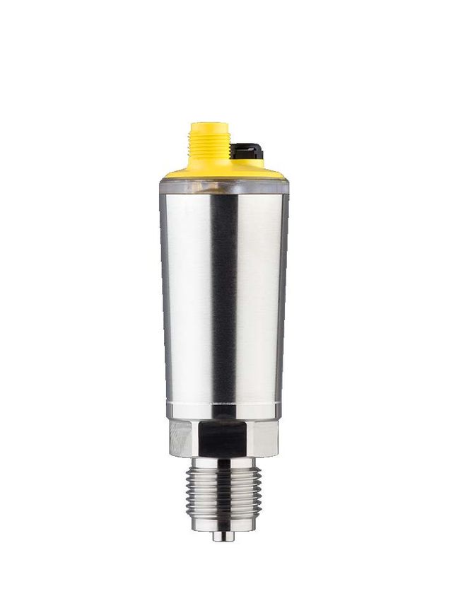
Die VEGABAR 28, 29 werden zur Messung der Druckarten Überdruck, Absolutdruck und Vakuum
verwendet. Messmedien sind Gase, Dämpfe und Flüssigkeiten
Die VEGABAR 28, 29 bestehen aus einem Elektronikgehäuse, einem Prozessanschlusselement
und einer Druckmesszelle.
Die VEGABAR 28, 29 sind geeignet für den Einsatz in explosionsfähiger Atmosphäre aller brennba-
ren Stoffe der Explosionsgruppen IIA, IIB und IIC.
Die VEGABAR 28, 29 sind für Anwendungen geeignet, die Betriebsmittel der Kategorie 3G
(EPL Gc) erfordern.
4 Anwendungsbereich
Die VEGABAR 28, 29 werden mit dem mechanischen Befestigungselement (Prozessanschluss)
im explosionsgefährdeten Bereich der Zone 2 errichtet, die ein Betriebsmittel der Kategorie 3G
(EPL Gc) erfordern.
5 Besondere Betriebsbedingungen ("X"-Kennzeichnung)
Die nachfolgende Übersicht listet alle besonderen Eigenschaften des VEGABAR 28, 29, welche
eine Kennzeichnung mit dem Symbol "X" im Zündschutzkennzeichen erforderlich machen.
Elektrostatische Aufladung (ESD)
Die Details hierzu sind dem Kapitel "Elektrostatische Aufladung (ESD)" dieser Sicherheitshinweise
zu entnehmen.
Umgebungstemperatur
Der in der EN 60079-0 festgelegte Umgebungstemperaturbereich kann eingeschränkt sein.
Die Details hierzu sind dem Kapitel "Thermische Daten" dieser Sicherheitshinweise zu entnehmen.
6 Sicherer Betrieb
Allgemeine Betriebsbedingungen
• Wenn die VEGABAR 28, 29 in explosionsgefährdeten Bereichen errichtet und betrieben wer-
den, müssen die allgemeinen Errichtungsbestimmungen für den Explosionsschutz EN 60079-
14 sowie diese Sicherheitshinweise beachtet werden
• Das Gerät muss nach der Zündtemperatur des Gases oder Dampfes und der Umgebungstem-
peratur ausgewählt werden, die Hinweise nach EN 60079-14 Kapitel 5.6 sind zu beachten
• Gerät nicht außerhalb der elektrischen, thermischen und mechanischen Angaben des Herstel-
lers betreiben
• Die Einsatzbedinguen für den Betrieb in nichtexplosionsgefährdeten Bereichen sind den Her-
stellerangaben (Betriebsanleitung) zu entnehmen
64873-01-210906
Anschlussbedingungen
• Die Anschlussleitung des VEGABAR 28, 29 ist fest und so zu verlegen, dass sie hinreichend
gegen Beschädigungen geschützt ist
6 VEGABAR 28, 29 • Erhöhte Sicherheit "e"• Beträgt die Temperatur an den Einführungsteilen mehr als 70 °C müssen entsprechende tempe-
raturbeständige Anschlussleitungen verwendet werden
• Dem VEGABAR 28, 29 kann bei Bedarf ein geeigneter Überspannungsschutz vorgeschaltet
werden
7 Wichtige Hinweise für die Montage und Wartung
Allgemeine Hinweise
Für die Montage, die elektrische Installation, die Inbetriebnahme und die Wartung des Gerätes
müssen folgende Voraussetzungen erfüllt werden:
• Das Personal muss über die Qualifikation entsprechend seiner Funktion und Tätigkeit verfügen
• Das Personal muss im Explosionsschutz ausgebildet sein
• Das Personal muss mit den entsprechenden gültigen Vorschriften vertraut sein, z. B. Projektie-
rung und Errichtung entsprechend der EN 60079-14
• Bei Arbeiten am Gerät (Montage, Installation, Wartung) ist sicherzustellen, dass keine explo-
sionsfähige Atmosphäre vorhanden ist, wenn möglich, Versorgungsstromkreise spannungslos
schalten
• Gerät entsprechend den Herstellerangaben und entsprechend den gültigen Vorschriften,
Regeln und Normen installieren
• Veränderungen am Gerät können den Explosionsschutz und somit die Sicherheit beeinträch-
tigen, daher ist es nicht zulässig, dass Reparaturen durch den Endverbraucher durchgeführt
werden
Montage
Bei Installation des Gerätes ist folgendes zu beachten:
• Die Geräte dürfen nicht in Prozessen verwendet werden bei denen die Messzelle beschädigt
werden kann
• Steckverbinder und Anschlusskabel:
–– Geräte dürfen nur mit zugelassenen Anschlusskabel und -stecker verwendet werden
–– Die Schutzart des Gerätes muss im angeschlossenen Zustand erhalten bleiben
–– Die Steckverbindungen am Gerät müssen immer mit einem passenden Gegenstück montiert
sein
–– Die Verbindung darf nicht unter Spannung getrennt oder verbunden werden
• Das Gerät muss (über den Prozessanschluss oder eine externe Erdungsklemme) an das
Erdungssystem angebunden werden
• Schlag- und Reibfunken sind zu vermeiden
Wartung
Zur Sicherstellung der Funktion des Gerätes wird eine periodische Sichtkontrolle empfohlen auf:
• Sichere Montage
• Keine mechanischen Beschädigungen oder Korrosion
• Durchgescheuerte oder anderweitig beschädigte Leitungen
• Keine lockere Verbindungen der Leitungsanschlüsse, Potenzialausgleichsanschlüsse
• Korrekte und eindeutig gekennzeichnete Leitungsverbindungen
8 Elektrostatische Aufladung (ESD)
64873-01-210906
Bezüglich der Gefahr elektrostatischer Aufladungen ist zu beachten:
• Reibung an den isolierenden Oberflächen vermeiden
• Isolierende Oberflächen nicht trocken reinigen
VEGABAR 28, 29 • Erhöhte Sicherheit "e" 79 Elektrische Daten
Versorgungs- und Signalstromkreis:
M12-Steckverbinder: Pin 1[+], Pin 3[-] 12 … 35 V DC
10 Mechanische Daten
Schutzart (EN 60529) M12-Steckverbinder: IP66/IP67/IP69
Überspannungskategorie III
Verschmutzungsgrad 4
11 Thermische Daten
VEGABAR 28
Prozesstemperatur
Messzellendichtung Zulässiger Umgebungstempera-
turbereich am Elektronikgehäuse
FKM VP2/A -20 … +130 °C (-4 … +266 °F)
EPDM A+P 70.10-02 -40 … +130 °C (-40 … +266 °F)
FFKM Perlast G75S -15 … +130 °C (-5 … +266 °F)
VEGABAR 29
Prozesstemperatur
Dichtung Zulässiger Umgebungstempera-
turbereich am Elektronikgehäuse
Standard -40 … +130 °C (-40 … +266 °F)
FKM VP2/A -20 … +130 °C (-4 … +266 °F)
EPDM A+P 70.10-02 -40 … +130 °C (-40 … +266 °F)
Temperaturderating
2
70 °C
(158 °F)
40 °C
(104 °F)
0 °C
(32 °F) 1
110 °C 130 °C
(230 °F) (266 °F)
Abb. 1: Temperaturderating VEGABAR 28, 29
64873-01-210906
1 Prozesstemperatur
2 Umgebungstemperatur
8 VEGABAR 28, 29 • Erhöhte Sicherheit "e"Temperaturklasse Zulässiger Prozesstemperaturbe- Zulässiger Umgebungstempera-
reich an der Messzelle in Zone 2 turbereich am Elektronikgehäuse
(EPL Gc) in Zone 2 (EPL Gc)
T41) -40 … +110 °C (+130 °C) -40 … +70 °C (+40 °C)
64873-01-210906
1)
Abhänigkeit Prozess- und Umgebungstemperatur beachten. Das Gerät darf
nur innerhalb der Kennlinie betrieben werden.
VEGABAR 28, 29 • Erhöhte Sicherheit "e" 9Contents
1 Area of applicability................................................................................................................ 12
2 Device configuration/-properties.......................................................................................... 13
3 General information................................................................................................................ 14
4 Application area...................................................................................................................... 14
5 Specific conditions of use ("X" identification).................................................................... 14
6 Safe operating mode.............................................................................................................. 14
7 Important information for mounting and maintenance....................................................... 15
8 Electrostatic charging (ESD)................................................................................................. 15
9 Electrical data......................................................................................................................... 15
10 Mechanical data...................................................................................................................... 15
11 Thermal data........................................................................................................................... 16
64873-01-210906
Supplementary documentation:
• Operating Instructions VEGABAR 28, 29
• EU declaration of conformity (Document ID: 61834)
Editing status: 2021-09-06
10 VEGABAR 28, 29 • Increased safety "e"DE Sicherheitshinweise
für den Einsatz in explosionsgefährdeten Bereichen
EN Safety instructions
for the use in hazardous areas
FR Consignes de sécurité
pour une application en atmosphères explosibles
IT Normative di sicurezza
per l'impiego in luoghi con pericolo di esplosione
ES Instrucciones de seguridad
para el empleo en áreas con riesgo de explosión
PT Normas de segurança
para utilização em zonas sujeitas a explosão
NL Veiligheidsaanwijzingen
voor gebruik op plaatsen waar ontploffingsgevaar kan heersen
SV Säkerhetsanvisningar
för användning i explosiionsfarliga områden
DA Sikkerhedsforskrifter
til anvendelse i explosionsfarlig atmosfare
FI Turvallisuusohjeet
räjähdysvaarallisisssa tiloissa käyttöä varten
EL Υποδείξεις ασΦαλείας
για τη χρησιμοποίηση σε περιοχές που υπάρχει κίνδυνος έκρηξης
DE Die vorliegenden Sicherheitshinweise sind im Download unter www.vega.com standardmäßig
in den Sprachen deutsch, englisch, französisch und spanisch verfügbar. Weitere EU-Landes-
sprachen stellt VEGA nach Anforderungen zur Verfügung.
EN These safety instructions are available as a standard feature in the download area under
www.vega.com in the languages German, English, French and Spanish. Further EU langua-
ges will be made available by VEGA upon request.
FR Les présentes consignes de sécurité sont disponibles au téléchargement sous
www.vega.com en standard en allemand, en anglais, en francais et en espagnol. VEGA met à
disposition d'autres langues de l'Union Européenne selon les exigences.
ES Las indicaciones de seguridad presentes están disponibles en la zona de descarga de
www.vega.com de forma estándar en los idiomas inglés, francés y español. VEGA pone a dis-
posición otros idiomas de la UE cuando son requeridos.
64873-01-210906
VEGABAR 28, 29 • Increased safety "e" 111 Area of applicability
These safety instructions apply to the VEGABAR 28, 29 of type series:
• VEGABAR 28
• VEGABAR 29
With process fittings:
VEGABAR 28
• C2 - Thread M20 x 1.5; EN 837; manometer connection / 316L
• AL - Thread M30 x 1.5 DIN 13; front-flush / 316L
• C3 - Thread G½, ISO 228-1; front-flush / 316L
• 9L - Thread G½ - 15 mm, DIN 3852-A; front-flush / Duplex (1.4462)
• LF - Thread ½ NPT, inside ¼ NPT, ASME B1.20.1 / 316L
• CS - Thread G½, ISO 228-1, Inner-ø 11,4mm / Duplex (1.4462)
• TJ - Thread G¼, ISO 228-1 / 316L
• TI - Thread ¼ NPT, ASME B1.20.1 / 316L
• N9 - Thread G¾, DIN 3852-E; front-flush / 316L
• C5 - Thread G1, ISO 228-1; front-flush / 316L
• DS - Thread 1 NPT, ASME B1.20.1; front-flush / 316L
• LX - Thread G1, ISO 228-1; front-flush / 316L (Ra < 0.76 µm), EPDM; for hygienic adapter with
O-ring sealing
• Z9 - Thread G1, DIN 3852-E / Duplex (1.4462)
• C9 - Thread 1½ NPT, ASME B1.20.1; front-flush / 316L
• DA - Thread G1½, DIN 3852-A; front-flush / 316L
• DU - Thread G½, EN 837; manometer connection / 316L
• DH - Thread G1, ISO 228-1; cone 40°, front-flush / 316L (Ra < 0.76 µm); for hygienic adapter
metallic sealing
• DN - Thread G½, inside G¼, ISO 228-1 / 316L
• VD - Clamp ¾" PN 40 (ø40 mm) DIN 32676, ISO 2852; front-flush / 316L (Ra < 0.76 µm)
• AV - Clamp 1" PN 40 (ø50.5 mm) DIN 32676, ISO 2852; front-flush / 316L (Ra < 0.76 µm)
• AT - Clamp 1½" PN 40 (ø50.5 mm) DIN 32676, ISO 2852; front-flush / 316L (Ra < 0.76 µm)
• AR - Clamp 2" PN 40 (ø64 mm) DIN 32676, ISO 2852; front-flush / 316L (Ra < 0.76 µm)
• E5 - Collar socket DN 25 PN 40, DIN 11851; front-flush / 316L (Ra < 0.76 µm)
• EZ - Collar socket DN 40 PN 40, DIN 11851; front-flush / 316L (Ra < 0.76 µm)
• NB - Collar socket DN 50 PN 25, DIN 11851; front-flush / 316L (Ra < 0.76 µm)
• E2 - Collar socket DN 40 PN 40 Form A, DIN 11864-1; front-flush / 316L (Ra < 0.8 µm)
• U5 - Collar socket DN 25 PN 40 Form A, DIN 11864-1; front-flush / 316L (Ra < 0.76 µm)
• FC - SMS DN 25 PN 6; front-flush / 316/316L (Ra < 0.8 µm)
• FA - SMS DN 38 PN 6 / 316L (Ra < 0.76 µm)
• FB - SMS DN 51 PN 6 / 316L (Ra < 0.76 µm)
• E7 - Ingold connection PN 10 / 316L (Ra < 0.76 µm)
• FR - Varivent N50-40 PN 25; front-flush / 316L (Ra < 0.76 µm)
• FS - Varivent F25 PN 25; front-flush / 316L (Ra < 0.76 µm)
• PF - Thread M38 x 1.5 PN 25; front-flush / 316L, EPDM
• 8V - Thread G1 with extension (ø21.7 x 34.5); front-flush / 316L
• RD - Hygienic adapter RD 52 PN 40; with compression nut / 316L (Ra < 0.38 µm); EPDM
VEGABAR 29
64873-01-210906
• C2 - Thread M20 x 1.5; EN 837; manometer connection / 316L
• YK - Thread M24 x 1.5; DIN 13; front-flush / 316L; EPDM
• LF - Thread ½ NPT, inside ¼ NPT, ASME B1.20.1 / 316L
• LY - Thread ½ NPT, ASME B1.20.1 / 316L
• LU - Thread G½, ISO 228-1; front-flush with O-ring / 316L; FKM
12 VEGABAR 28, 29 • Increased safety "e"• 3P - Thread G½, ISO 228-1; front-flush with O-ring / 316L; EPDM
• 9L - Thread G½ - 15 mm, DIN 3852-A; front-flush / Duplex (1.4462)
• TJ - Thread G¼, ISO 228-1 / 316L
• TI - Thread ¼ NPT, ASME B1.20.1 / 316L
• N9 - Thread G¾, DIN 3852-E; front-flush / 316L
• LX - Thread G1, ISO 228-1; front-flush / 316L (Ra < 0.76 µm), EPDM; for hygienic adapter with
O-ring sealing
• C5 - Thread G1, ISO 228-1; front-flush / 316L; FKM
• 3Q - Thread G1, ISO 228-1; front-flush / 316L; EPDM
• C9 - Thread 1½ NPT, ASME B1.20.1; front-flush / 316L
• DA - Thread G1½, DIN 3852-A; front-flush / 316L
• DU - Thread G½, EN 837; manometer connection / 316L
• DH - Thread G1, ISO 228-1; cone 40°, front-flush / 316L (Ra < 0.76 µm); for hygienic adapter
metallic sealing
• DN - Thread G½, inside G¼, ISO 228-1 / 316L
• AV - Clamp 1" PN 40 (ø50.5 mm) DIN 32676, ISO 2852; front-flush / 316L (Ra < 0.76 µm)
• AT - Clamp 1½" PN 40 (ø50.5 mm) DIN 32676, ISO 2852; front-flush / 316L (Ra < 0.76 µm)
• AR - Clamp 2" PN 40 (ø64 mm) DIN 32676, ISO 2852; front-flush / 316L (Ra < 0.76 µm)
• E5 - Collar socket DN 25 PN 40, DIN 11851; front-flush / 316L (Ra < 0.76 µm)
• EZ - Collar socket DN 40 PN 40, DIN 11851; front-flush / 316L (Ra < 0.76 µm)
• NB - Collar socket DN 50 PN 25, DIN 11851; front-flush / 316L (Ra < 0.76 µm)
• E2 - Collar socket DN 40 PN 40 Form A, DIN 11864-1; front-flush / 316L (Ra < 0.8 µm)
• U5 - Collar socket DN 25 PN 40 Form A, DIN 11864-1; front-flush / 316L (Ra < 0.76 µm)
• FC - SMS DN 25 PN 6; front-flush / 316/316L (Ra < 0.8 µm)
• FA - SMS DN 38 PN 6 / 316L (Ra < 0.76 µm)
• FB - SMS DN 51 PN 6 / 316L (Ra < 0.76 µm)
• E7 - Ingold connection PN 10 / 316L; EPDM (Ra < 0.76 µm)
• FR - Varivent N50-40 PN 25; front-flush / 316L (Ra < 0.76 µm)
• FS - Varivent F25 PN 25; front-flush / 316L (Ra < 0.76 µm)
• RD - Hygienic adapter RD 52 PN 40; with compression nut / 316L (Ra < 0.38 µm); EPDM
With the electrical connection:
• M12 x 1 Stainless Steel / IP66/IP67/IP69
With the electronics versions:
• Two-wire 4 … 20 mA
• Three-wire with IO-Link (2 x transistor or 4 … 20 mA plus 1 x transistor)
The devices have been assessed by the manufacturer on his own responsibility according to the
following standards:
• EN IEC 60079-0: 2018
• EN IEC 60079-7/A1: 2018
The EU conformity declaration was drawn up in accordance with EU Directive 2014/34/EU, Article
13 c, Appendix VIII
Type of protection marking:
• II 3G Ex ec IIC T4 Gc
64873-01-210906
2 Device configuration/-properties
The detailed device configurations can be retrieved using the serial number search on our home-
page.
Move to "www.vega.com" and enter in the search field the serial number of your instrument.
VEGABAR 28, 29 • Increased safety "e" 13Alternatively, you can find all via your smartphone:
• Download the VEGA Tools app from the "Apple App Store", "Google Play Store" or "
Baidu Store"
• Scan the DataMatrix code on the type label of the instrument or
• Enter the serial number manually in the app
3 General information
The VEGABAR 28, 29 are used to measure the pressure types gauge pressure, absolute pressure
and vacuum. Measured media are gases, vapours and liquids
The VEGABAR 28, 29 consist of an electronics housing, a process connection element and a pres-
sure measuring cell.
The VEGABAR 28, 29 are suitable for applications in hazardous atmospheres of all combustible
materials of explosion groups IIA, IIB and IIC.
The VEGABAR 28, 29 are suitable for applications requiring category 3G (EPL Gc) instruments.
4 Application area
The VEGABAR 28, 29 with the mechanical fixing element (process fitting) are installed in hazardous
areas of zone 2 requiring category 3G (EPL Gc) instruments.
5 Specific conditions of use ("X" identification)
The following overview is listing all special properties of VEGABAR 28, 29, which make a labelling
with the symbol "X" in the classification mark necessary.
Electrostatic charging (ESD)
You can find the details in chapter "Electrostatic charging (ESD)" of these safety instructions.
Ambient temperature
The ambient temperature range stipulated in EN 60079-0 can be limited.
You can find the details in chapter "Thermal data" of these safety instructions.
6 Safe operating mode
General operating conditions
• If the VEGABAR 28, 29** are installed and operated in hazardous areas, the general Ex installa-
tion regulations EN 60079-14 as well as these safety instructions must be observed
• The device must be selected according to the ignition temperature of the gas or vapour and the
ambient temperature, the instructions according to EN 60079-14 chapter 5.6 must be observed
• Do not operate the instrument outside the electrical, thermal and mechanical specifications of
the manufacturer
• The operating conditions for operation in non-hazardous areas can be found in the manufacturer
specifications (operating instructions)
Connection conditions
• The connection cable of VEGABAR 28, 29 has to be wired fix and in such a way that damages
can be excluded
64873-01-210906
• If the temperature at the entry parts exceeds 70 °C, temperature-resistant connection cables
must be used
• If necessary, a suitable overvoltage arrester can be connected in front of the VEGABAR 28, 29
14 VEGABAR 28, 29 • Increased safety "e"7 Important information for mounting and maintenance
General instructions
The following requirements must be fulfilled for mounting, electrical installation, setup and mainte-
nance of the instrument:
• The staff must be qualified according the respective tasks
• The staff must be trained in explosion protection
• The staff must be familiar with the respectively valid regulations, e.g. planning and installation
acc. to EN 60079-14
• Make sure when working on the instrument (mounting, installation, maintenance) that there is no
explosive atmosphere present, the supply circuits should be voltage-free, if possible.
• The instrument has to be mounted according to the manufacturer specifications and the valid
regulations and standards
• Modifications on the instrument can influence the explosion protection and hence the safety,
therefore repairs are not permitted to be conducted by the end user
Mounting
When installing the device, observe the following:
• The devices must not be used in processes where the measuring cell can be damaged
• Plug connector and connection cable:
–– Devices may only be used with approved cables and plugs
–– The protection class of the device must be maintained when connected
–– The plug connections on the device must always be fitted with a suitable counterpart
–– The connection must not be disconnected or connected under voltage
• The instrument must be connected to the grounding system (via the process fitting or an exter-
nal grounding clamp)
• Impact and friction sparks are to be avoided
Maintenance
To ensure the functionality of the device, periodic visual inspection is recommended for:
• Secure mounting
• No mechanical damages or corrosion
• Worn or otherwise damaged cables
• No loose connections of the line connections, equipotential bonding connections
• Correct and clearly marked cable connections
8 Electrostatic charging (ESD)
Take note in case of danger of electrostatic charges:
• Avoid friction on the insulating surfaces
• Do not clean insulating surfaces with a dry cloth
9 Electrical data
Supply and signal circuit:
M12 plug connector: Pin 1[+], Pin 3[-] 12 … 35 V DC
64873-01-210906
10 Mechanical data
Protection (EN 60529) M12-Steckverbinder: IP66/IP67/IP69
VEGABAR 28, 29 • Increased safety "e" 15Overvoltage category III
Pollution degree 4
11 Thermal data
VEGABAR 28
Process temperature
Measuring cell seal Permissible ambient temperature
range on the electronics housing
FKM VP2/A -20 … +130 °C (-4 … +266 °F)
EPDM A+P 70.10-02 -40 … +130 °C (-40 … +266 °F)
FFKM Perlast G75S -15 … +130 °C (-5 … +266 °F)
VEGABAR 29
Process temperature
Seal Permissible ambient temperature
range on the electronics housing
Standard -40 … +130 °C (-40 … +266 °F)
FKM VP2/A -20 … +130 °C (-4 … +266 °F)
EPDM A+P 70.10-02 -40 … +130 °C (-40 … +266 °F)
Temperature derating
2
70 °C
(158 °F)
40 °C
(104 °F)
0 °C
(32 °F) 1
110 °C 130 °C
(230 °F) (266 °F)
Abb. 2: Temperature derating VEGABAR 28, 29
1 Process temperature
2 Ambient temperature
Temperature class Permissible process temperature Permissible ambient temperature
range at the measuring cell in zo- range on the electronics housing
ne 2 (EPL Gc) in zone 2 (EPL Gc)
T42) -40 … +110 °C (+130 °C) -40 … +70 °C (+40 °C)
64873-01-210906
2)
Observe dependence of process and ambient temperature. The device may
only be operated within the characteristic curve.
16 VEGABAR 28, 29 • Increased safety "e"Table des matières
1 Validité..................................................................................................................................... 19
2 Configuration / propriétés des appareils............................................................................. 20
3 Généralités.............................................................................................................................. 21
4 Domaine d'application............................................................................................................ 21
5 Conditions d'utilisation particulières (caractérisation "X")............................................... 21
6 Fonctionnement sécurisé...................................................................................................... 21
7 Instructions importantes pour le montage et l'entretien.................................................... 22
8 Charge électrostatique (ESD)................................................................................................ 23
9 Caractéristiques électriques................................................................................................. 23
10 Caractéristiques mécaniques................................................................................................ 23
11 Caractéristiques thermiques................................................................................................. 23
64873-01-210906
Documentation complémentaire:
• Notices de mise en service VEGABAR 28, 29
• Déclaration de conformité UE (ID du document : 61834)
Date de rédaction :2021-09-06
VEGABAR 28, 29 • Sécurité augmentée "e" 17DE Sicherheitshinweise
für den Einsatz in explosionsgefährdeten Bereichen
EN Safety instructions
for the use in hazardous areas
FR Consignes de sécurité
pour une application en atmosphères explosibles
IT Normative di sicurezza
per l'impiego in luoghi con pericolo di esplosione
ES Instrucciones de seguridad
para el empleo en áreas con riesgo de explosión
PT Normas de segurança
para utilização em zonas sujeitas a explosão
NL Veiligheidsaanwijzingen
voor gebruik op plaatsen waar ontploffingsgevaar kan heersen
SV Säkerhetsanvisningar
för användning i explosiionsfarliga områden
DA Sikkerhedsforskrifter
til anvendelse i explosionsfarlig atmosfare
FI Turvallisuusohjeet
räjähdysvaarallisisssa tiloissa käyttöä varten
EL Υποδείξεις ασΦαλείας
για τη χρησιμοποίηση σε περιοχές που υπάρχει κίνδυνος έκρηξης
DE Die vorliegenden Sicherheitshinweise sind im Download unter www.vega.com standardmäßig
in den Sprachen deutsch, englisch, französisch und spanisch verfügbar. Weitere EU-Landes-
sprachen stellt VEGA nach Anforderungen zur Verfügung.
EN These safety instructions are available as a standard feature in the download area under
www.vega.com in the languages German, English, French and Spanish. Further EU langua-
ges will be made available by VEGA upon request.
FR Les présentes consignes de sécurité sont disponibles au téléchargement sous
www.vega.com en standard en allemand, en anglais, en francais et en espagnol. VEGA met à
disposition d'autres langues de l'Union Européenne selon les exigences.
ES Las indicaciones de seguridad presentes están disponibles en la zona de descarga de
www.vega.com de forma estándar en los idiomas inglés, francés y español. VEGA pone a dis-
posición otros idiomas de la UE cuando son requeridos.
64873-01-210906
18 VEGABAR 28, 29 • Sécurité augmentée "e"1 Validité
Ces consignes de sécurité sont valables pour les VEGABAR 28, 29 des séries :
• VEGABAR 28
• VEGABAR 29
Avec les raccords process :
VEGABAR 28
• C2 - Filetage M20 x 1,5; EN 837; raccord de manomètre / 316L
• AL - Filetage M30 x 1,5 DIN 13; arasant / 316L
• C3 - Filetage G½, ISO 228-1; arasant / 316L
• 9L - Filetage G½ - 15 mm, DIN 3852-A; arasant / Duplex (1.4462)
• LF - Filetage ½ NPT, intérieur ¼ NPT, ASME B1.20.1 / 316L
• CS - Filetage G½, ISO 228-1, Intérieur-ø 11,4mm / Duplex (1.4462)
• TJ - Filetage G¼, ISO 228-1 / 316L
• TI - Filetage ¼ NPT, ASME B1.20.1 / 316L
• N9 - Filetage G¾, DIN 3852-E; arasant / 316L
• C5 - Filetage G1, ISO 228-1; arasant / 316L
• DS - Filetage 1 NPT, ASME B1.20.1; arasant / 316L
• LX - Filetage G1, ISO 228-1; arasant / 316L (Ra < 0,76 µm), EPDM; pour adaptateur hygiène
avec joint torique
• Z9 - Filetage G1, DIN 3852-E / Duplex (1.4462)
• C9 - Filetage 1½ NPT, ASME B1.20.1; arasant / 316L
• DA - Filetage G1½, DIN 3852-A; arasant / 316L
• DU - Filetage G½, EN 837; raccord de manomètre / 316L
• DH - Filetage G1, ISO 228-1; cône 40°, arasant / 316L (Ra < 0,76 µm); pour adaptateur hygiène
avec étanchéité métallique
• DN - Filetage G½, intérieur G¼, ISO 228-1 / 316L
• VD - Clamp ¾" PN 40 (ø40 mm) DIN 32676, ISO 2852; arasant / 316L (Ra < 0,76 µm)
• AV - Clamp 1" PN 40 (ø50,5 mm) DIN 32676, ISO 2852; arasant / 316L (Ra < 0,76 µm)
• AT - Clamp 1½" PN 40 (ø50,5 mm) DIN 32676, ISO 2852; arasant / 316L (Ra < 0,76 µm)
• AR - Clamp 2" PN 40 (ø64 mm) DIN 32676, ISO 2852; arasant / 316L (Ra < 0,76 µm)
• E5 - Tubulure à collet DN 25 PN 40, DIN 11851; arasant / 316L (Ra < 0,76 µm)
• EZ - Tubulure à collet DN 40 PN 40, DIN 11851; arasant / 316L (Ra < 0,76 µm)
• NB - Tubulure à collet DN 50 PN 25, DIN 11851; arasant / 316L (Ra < 0,76 µm)
• E2 - Tubulure à collet DN 40 PN 40 forme A, DIN 11864-1; arasant / 316L (Ra < 0,8 µm)
• U5 - Tubulure à collet DN 25 PN 40 forme A, DIN 11864-1; arasant / 316L (Ra < 0,76 µm)
• FC - SMS DN 25 PN 6; arasant / 316/316L (Ra < 0,8 µm)
• FA - SMS DN 38 PN 6 / 316L (Ra < 0,76 µm)
• FB - SMS DN 51 PN 6 / 316L (Ra < 0,76 µm)
• E7 - Raccord Ingold PN 10 / 316L (Ra < 0,76 µm)
• FR - Varivent N50-40 PN 25; arasant / 316L (Ra < 0,76 µm)
• FS - Varivent F25 PN 25; arasant / 316L (Ra < 0,76 µm)
• PF - Filetage M38 x 1,5 PN 25; arasant / 316L, EPDM
• 8V - Filetage G1 avec tube (ø21,7 x 34,5); arasant / 316L
• RD - Adaptateur hygiènique RD 52 PN 40; avec écrou union / 316L (Ra < 0,38 µm); EPDM
VEGABAR 29
64873-01-210906
• C2 - Filetage M20 x 1,5; EN 837; raccord de manomètre / 316L
• YK - Filetage M24 x 1,5; DIN 13; arasant / 316L; EPDM
• LF - Filetage ½ NPT, intérieur ¼ NPT, ASME B1.20.1 / 316L
• LY - Filetage ½ NPT, ASME B1.20.1 / 316L
• LU - Filetage G½, ISO 228-1; arasant avec joint torique / 316L; FKM
VEGABAR 28, 29 • Sécurité augmentée "e" 19• 3P - Filetage G½, ISO 228-1; arasant avec joint torique / 316L; EPDM
• 9L - Filetage G½ - 15 mm, DIN 3852-A; arasant / Duplex (1.4462)
• TJ - Filetage G¼, ISO 228-1 / 316L
• TI - Filetage ¼ NPT, ASME B1.20.1 / 316L
• N9 - Filetage G¾, DIN 3852-E; arasant / 316L
• LX - Filetage G1, ISO 228-1; arasant / 316L (Ra < 0,76 µm), EPDM; pour adaptateur hygiène
avec joint torique
• C5 - Filetage G1, ISO 228-1; arasant / 316L; FKM
• 3Q - Filetage G1, ISO 228-1; arasant / 316L; EPDM
• C9 - Filetage 1½ NPT, ASME B1.20.1; arasant / 316L
• DA - Filetage G1½, DIN 3852-A; arasant / 316L
• DU - Filetage G½, EN 837; raccord de manomètre / 316L
• DH - Filetage G1, ISO 228-1; cône 40°, arasant / 316L (Ra < 0,76 µm); pour adaptateur hygiène
avec étanchéité métallique
• DN - Filetage G½, intérieur G¼, ISO 228-1 / 316L
• AV - Clamp 1" PN 40 (ø50,5 mm) DIN 32676, ISO 2852; arasant / 316L (Ra < 0,76 µm)
• AT - Clamp 1½" PN 40 (ø50,5 mm) DIN 32676, ISO 2852; arasant / 316L (Ra < 0,76 µm)
• AR - Clamp 2" PN 40 (ø64 mm) DIN 32676, ISO 2852; arasant / 316L (Ra < 0,76 µm)
• E5 - Tubulure à collet DN 25 PN 40, DIN 11851; arasant / 316L (Ra < 0,76 µm)
• EZ - Tubulure à collet DN 40 PN 40, DIN 11851; arasant / 316L (Ra < 0,76 µm)
• NB - Tubulure à collet DN 50 PN 25, DIN 11851; arasant / 316L (Ra < 0,76 µm)
• E2 - Tubulure à collet DN 40 PN 40 forme A, DIN 11864-1; arasant / 316L (Ra < 0,8 µm)
• U5 - Tubulure à collet DN 25 PN 40 forme A, DIN 11864-1; arasant / 316L (Ra < 0,76 µm)
• FC - SMS DN 25 PN 6; arasant / 316/316L (Ra < 0,8 µm)
• FA - SMS DN 38 PN 6 / 316L (Ra < 0,76 µm)
• FB - SMS DN 51 PN 6 / 316L (Ra < 0,76 µm)
• E7 - Raccord Ingold PN 10 / 316L; EPDM (Ra < 0,76 µm)
• FR - Varivent N50-40 PN 25; arasant / 316L (Ra < 0,76 µm)
• FS - Varivent F25 PN 25; arasant / 316L (Ra < 0,76 µm)
• RD - Adaptateur hygiènique RD 52 PN 40; avec écrou union / 316L (Ra < 0,38 µm); EPDM
Avec les raccords électriques :
• M12 x 1 Inox / IP66/IP67/IP69
Avec les versions électroniques :
• Deux fils 4 … 20 mA
• Trois fils avec IO-Link (2 x transistor ou 4 … 20 mA plus 1 x transistor)
Les appareils ont été évalués par le fabricant sous notre propre responsabilité selon les normes
suivantes :
• EN IEC 60079-0: 2018
• EN IEC 60079-7/A1: 2018
La déclaration de conformité UE a été rédigée conformément à la Directive UE 2014/34/EU, article
13 c, annexe VIII
Mode de protection :
• II 3G Ex ec IIC T4 Gc
64873-01-210906
2 Configuration / propriétés des appareils
Vous pouvez consulter la configuration détaillée de l'appareil au moyen de la recherche de numéros
de série sur notre page d'accueil.
Rendez-vous sur "www.vega.com" et indiquez dans la zone de recherche le numéro de série de
20 VEGABAR 28, 29 • Sécurité augmentée "e"votre appareil.
Vous trouverez en alternative tout sur votre smartphone :
• Télécharger l'application VEGA Tools depuis l'"Apple App Store", le "Google Play Store" ou le "
Baidu Store"
• Numériser le code DataMatrix situé sur la plaque signalétique de l'appareil ou
• Entrer le numéro de série manuellement dans l'application
3 Généralités
Les VEGABAR 28, 29 sont utilisés pour la mesure des types de pression suivants : surpression,
pression absolue et vide. La mesure est effectuée dans les gaz, les vapeurs et les liquides.
Les VEGABAR 28, 29 sont composés d'un boîtier de l'électronique, d'un élément de raccord pro-
cess et d'une cellule de mesure.
Les VEGABAR 28, 29 sont appropriés pour l'utilisation dans des atmosphères explosives de toutes
les matières inflammables des groupes d'explosion IIA, IIB et IIC.
Les VEGABAR 28, 29 sont adaptés aux applications nécessitant du matériel de catégorie 3G
(EPL Gc).
4 Domaine d'application
Les VEGABAR 28, 29 sont installés avec l'élément de fixation mécanique (raccord process) dans
l'atmosphère explosible de la zone 2 nécessitant un matériel de la catégorie 3G (matériel EPL Gc).
5 Conditions d'utilisation particulières (caractérisation "X")
L'aperçu ci-après liste toutes les caractéristiques spécifiques au VEGABAR 28, 29 nécessitant une
caractérisation par le symbole "X" dans le marquage ATEX.
Charge électrostatique (ESD)
Les détails à cet effet sont indiqués au chapitre "Charge électrostatique" des présentes consignes
de sécurité.
Température ambiante
La plage de température ambiante déterminée dans EN 60079-0 peut être limitée.
Les détails sont indiqués au chapitre "Caractéristiques thermiques" des présentes consignes de
sécurité.
6 Fonctionnement sécurisé
Conditions de service générales
• Si les VEGABAR 28, 29 sont installés et exploités en atmosphères explosibles, il faudra respec-
ter les règles d'installation générales concernant la protection contre les explosions, EN 60079-
14, ainsi que les présentes consignes de sécurité
• Il convient de choisir l'appareil en fonction de la température d'ignition du gaz ou de la vapeur
et de la température ambiante, tenez compte à cet effet des instructions selon EN 60079-14 au
chapitre 5.6.
• Ne pas utiliser l'appareil hors des spécifications électriques, thermiques et mécaniques du
fabricant
64873-01-210906
• Les conditions de mise en œuvre pour une exploitation dans des zones à atmosphère non
explosible figurent dans les indications du fabricant (notice de mise en service)
VEGABAR 28, 29 • Sécurité augmentée "e" 21Conditions de raccordement
• Le câble de raccordement du VEGABAR 28, 29 doit être posé de manière fixe et de telle mani-
ère qu'il soit suffisamment protégé contre les endommagements.
• Si la température au niveau des entrées de câble dépasse 70 °C, il faudra utiliser du câble de
raccordement adéquat et résistant aux températures sur site
• Si besoin est, une protection appropriée contre les surtensions peut être installée en amont du
VEGABAR 28, 29
7 Instructions importantes pour le montage et l'entretien
Remarques générales
Pour le montage, l'installation électrique, la mise en service et l'entretien de l'appareil, les conditions
suivantes doivent être réunies :
• Le personnel doit disposer des qualifications correspondant à ses fonctions et activités
• Le personnel doit être formé à la protection contre les explosions
• Le personnel doit être familier des dispositions en vigueur, par ex. sur la conception, sélection et
construction d'installations électriques selon la norme EN 60079-14
• Lors des opérations sur l'appareil (montage, installation, entretien), il est impératif de s'assurer
de l'absence totale d'atmosphère explosible, et si possible mettre les circuits électriques
d'alimentation hors tension.
• installer l'appareil dans le respect des préconisations du fabricant et conformément aux régle-
mentations, directives et normes
• Les modifications de l'appareil peuvent affecter la protection anti-déflagrante et ainsi la sécurité,
il n'est donc pas autorisé que les réparations soient effectuées par l'utilisateur final
Montage
Il convient de prendre en compte ce qui suit lors de l'installation de l'appareil :
• Les appareils ne doivent pas être utilisés dans des processus avec lesquels la cellule de
mesure pourrait être endommagée
• Connecteur et câble de raccordement :
–– Il est permis d'utiliser les appareils uniquement avec le câble de raccordement et le con-
necteur agréés
–– La protection de l'appareil doit être maintenue en état raccordé
–– Les connexions enfichées sur l'appareil doivent toujours être montées avec un équivalent
adapté
–– Il est interdit de brancher ou de débrancher la connexion en état sous tension
• L'appareil doit être intégré dans le système de mise à la terre (via le raccord process ou au
moyen d'une borne de terre externe)
• Évitez impérativement les étincelles dues aux chocs ou à la friction
Maintenance
Pour garantir le fonctionnement de l'appareil, un contrôle visuel périodique est recommandé con-
cernant :
• Fiabilité du montage
• Aucune détérioration mécanique ou corrosion
• Câbles usés ou autrement détériorés
• Aucune connexion lâche des raccordements de conduite, raccordements de compensation de
64873-01-210906
potentiel
• Connexions de câbles correctes et clairement marquées
22 VEGABAR 28, 29 • Sécurité augmentée "e"8 Charge électrostatique (ESD)
À respecter en matière de risques électrostatiques :
• Éviter la friction sur les surfaces isolantes
• Ne pas nettoyer les surfaces isolantes à sec
9 Caractéristiques électriques
Circuit d'alimentation et signal :
Connecteur M12 : broche 1[+], broche 3[-] 12 … 35 V DC
10 Caractéristiques mécaniques
Protection (EN 60529) M12-Steckverbinder: IP66/IP67/IP69
Catégorie de surtensions III
Degré de pollution 4
11 Caractéristiques thermiques
VEGABAR 28
Température process
Joint de la cellule de mesure Température ambiante admissib-
le sur le boîtier de l'électronique
FKM VP2/A -20 … +130 °C (-4 … +266 °F)
EPDM A+P 70.10-02 -40 … +130 °C (-40 … +266 °F)
FFKM Perlast G75S -15 … +130 °C (-5 … +266 °F)
VEGABAR 29
Température process
Joint d'étanchéité Température ambiante admissib-
le sur le boîtier de l'électronique
Standard -40 … +130 °C (-40 … +266 °F)
FKM VP2/A -20 … +130 °C (-4 … +266 °F)
EPDM A+P 70.10-02 -40 … +130 °C (-40 … +266 °F)
64873-01-210906
VEGABAR 28, 29 • Sécurité augmentée "e" 23Derating de température
2
70 °C
(158 °F)
40 °C
(104 °F)
0 °C
(32 °F) 1
110 °C 130 °C
(230 °F) (266 °F)
Abb. 3: Derating de température VEGABAR 28, 29
1 Température process
2 Température ambiante
Classe de température Plage de température process Plage de température ambian-
admissible sur la cellule de me- te admissible sur le boîtier de
sure en zone 2 (EPL Gc) l'électronique en zone 2 (EPL Gc)
T43) -40 … +110 °C (+130 °C) -40 … +70 °C (+40 °C)
64873-01-210906
3)
Tenir compte de la dépendance de température ambiante et process. Il est
permis d'exploiter l'appareil uniquement au sein de la courbe caractéristique.
24 VEGABAR 28, 29 • Sécurité augmentée "e"Sie können auch lesen