FL 220HV - SSD Safety Ltd
←
→
Transkription von Seiteninhalten
Wenn Ihr Browser die Seite nicht korrekt rendert, bitte, lesen Sie den Inhalt der Seite unten
DE | EN | FR
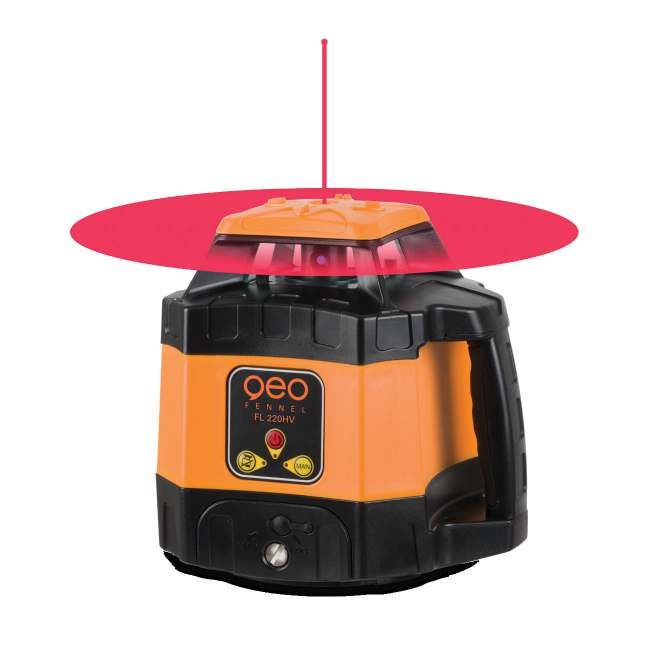
FL 220HV
BEDIENUNGSANLEITUNG
USER MANUAL
MODE D‘EMPLOI
www.geo-fennel.de
www.geo-fennel.com
www.geo-fennel.fr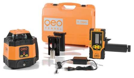
DE

     Sehr geehrter Kunde,

     vielen Dank für das Vertrauen, welches Sie uns beim Erwerb Ihres neuen geo-FENNEL-Gerätes ent-
     gegengebracht haben. Dieses hochwertige Qualitätsprodukt wurde mit größter Sorgfalt produziert und
     qualitätsgeprüft.

     Die beigefügte Anleitung wird Ihnen helfen, das Gerät sachgemäß zu bedienen. Bitte lesen Sie ins-
     besondere auch die Sicherheitshinweise vor der Inbetriebnahme aufmerksam durch. Nur ein sachge-
     rechter Gebrauch gewährleistet einen langen und zuverlässigen Betrieb.

     geo-FENNEL
     Precision by tradition.

         Inhaltsverzeichnis
         1. Lieferumfang                                                                            A
         2. Stromversorgung                                                                         B
         3. Bedienelemente                                                                          C
         4. Bedienung                                                                               D
         5. Empfänger                                                                               E
         6. Sicherheitshinweise                                                                     F

A        LIEFERUMFANG
     ·    Rotationslaser FL 220HV
     ·    Empfänger FR 45 mit Halteklammer
     ·    Akku und Ladegerät
     ·    Batteriefach für Alkalinebatterien
     ·    Koffer
     ·    Bedienungsanleitung

2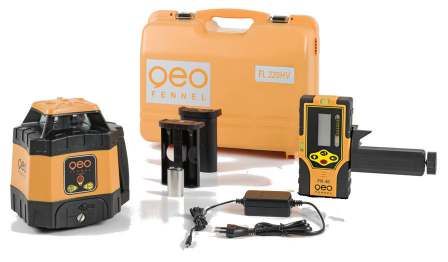
DE

EIGENSCHAFTEN

·       Arbeitsbereich bis 400 m Ø
·       Staub-/Wasserschutz IP 54
·       90° Lotstrahl
·       Automatische TILT-Funktion
·       Abschaltung außerhalb des Selbstnivellierbereiches
·       Manuellfunktion

    Technische Daten
    Selbstnivellierung                                       horizontal / vertikal
    Selbstnivellierbereich                                   ± 5°
    Laserklasse                                              2
    Genauigkeit
    ·    horizontal                                          ± 1,0 mm / 10 m
    ·    vertikal                                            ± 1,5 mm / 10 m
    Arbeitsbereich mit FR 45 Ø                               400 m
    90° Lotpunkt                                             ja
    TILT-Funktion                                            ja
    Manuellfunktion                                          ja
    Rotationsgeschwindigkeit                                 600 U/Min.
    Betriebsdauer / Stromversorgung                          20 h (NiMH)
    Temperaturbereich                                        -20°C - +50°C
    Staub-/Wasserschutz                                      IP 54

                                                                                      3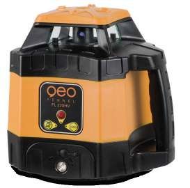
DE

B     STROMVERSORGUNG
     Der Laser ist mit einem NiMH-Akkupack ausgestattet. Alternativ kann er mit handelsüblichen
     Alkalinebatterien betrieben werden.

     1) Alkalinebatterien in das dafür vorgesehene Batteriefach einlegen (auf Polarität achten) und das
        Fach ins Gerät einfügen.

     ODER

     2) Wiederaufladbares NiMH-Akkufach ins Gerät einfügen.

        1)                                                       2)

     AKKU LADEN

     Ladegerät mit Ladebuchse am Gerät und Stromnetz verbinden. Wenn die Lade-LED rot leuchtet, läuft
     der Ladevorgang. Leuchtet die LED grün, ist der Akku voll aufgeladen.

     BEACHTE
     Der Akku kann im Gerät und auch außerhalb des Gerätes geladen werden.

     Ladezustandsanzeige: Wenn die AN-/AUS-LED am Gerät blinkt, muss der Akku geladen werden.

                                                              Lade-LED

4
DE

 BEDIENELEMENTE                                                                                        C
1.   Laseraustrittsfenster                                      1                         2
2.   Rotorkopf
3.   Handgriff
4.   Batteriefach
5.   Bedienfeld
6.   Auflagepunkt für Vertikalbetrieb
7.   5/8“-Gewinde vertikal                                  5                                      3
8.   5/8“-Gewinde horizontal
9.   Buchse für Ladegerät

                                                    6       4

                                                                                      9

                                                            5/8″
                                                        7

                                                     8 5/8″

 BEDIENUNG                                                                                             D
HORIZONTALEINSATZ

Das Gerät auf einer einigermaßen ebenen Fläche oder auf einem Stativ aufstellen.

VERTIKALEINSATZ

Gerät vertikal (auf der Seite mit dem Gewinde) aufstellen oder mit dem Vertikalgewinde auf einem
Stativ befestigen.

                                                                                                       5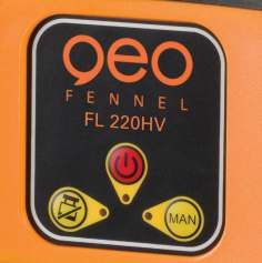
DE

     Direkt nach dem Einschalten beginnt das Gerät, sich selbst zu nivellieren (Laserpunkt blinkt). Wenn
     der Selbstnivellierungsvorgang abgeschlossen ist, beginnt sich der Rotorkopf zu drehen. Wenn keine
     Selbstnivellierung erfolgt, wurde das Gerät außerhalb des Selbstnivellierbereiches von ± 5° aufgestellt
     (Warnsignal ertönt). Gerät dann auf eine waagerechtere Ebene stellen.

                                                          1.   AN-/AUS-Taste
                                                          2.   AN-/AUS-LED
                                                          3.   MANUELL-Taste
                                                          4.   MANUELL-LED
                                                          5.   TILT-LED
                                               1          6.   TILT-Taste
                                              2

       6                                      3

                        5    4

     GERÄT AN/AUS-SCHALTEN (1)

     Gerät mit Taste (1) ein- und ausschalten. Wenn die AN/AUS-LED (2) rot leuchtet, ist das Gerät einge-
     schaltet. Zunächst blinkt der Laserpunkt, dann beginnt die Selbstnivellierung des Gerätes automatisch.
     Die TILT-LED (5) blinkt währenddessen. Wenn die Selbstnivellierung abgeschlossen ist, dreht sich
     der Rotorkopf mit 600 U/Min, und die TILT-LED (5) leuchtet dauerhaft (= TILT-Funktion aktiv).

     Wenn die AN-/AUS-LED (2) im Normalbetrieb zu blinken beginnt, muss der Akku geladen werden.

     TILT-FUNKTION (6)

     Die TILT-Funktion ist nach Abschluss der Selbstnivellierung automatisch aktiv.
     Wenn das Gerät aus seiner Lage gebracht wird, stoppt die Rotation, und die TILT-LED blinkt.

     1. TILT-Taste (6) einmal drücken: Die Rotation läuft wieder an - aber mit deaktivierter TILT-Funktion.
     2. TILT-Taste (6) zweimal drücken: Die Rotation läuft wieder an, die Selbstnivellierung wird durchge-
        führt, und der Laser arbeitet wieder mit aktivierter TILT-Funktion.

     Zum Deaktivieren der TILT-Funktion nach abgeschlossener Selbstnivellierung Taste (6) drücken.

6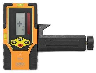
DE

MANUELL-FUNKTION (3)

Gerät einschalten, Selbstnivellierung abwarten und nach abgeschlossener Sellbstnivellierung
MANUELL-Taste (3) drücken. Die TILT-LED (5) geht aus, die MANUELL-LED (4) leuchtet dauerhaft.
Nun kann das Gerät auch in Schrägposition, z. B mit Neigungswinkeladapter eingesetzt werden,
ohne dass TILT-Alarm ausgelöst wird.

Bei vertikaler Verwendung kann mit Hilfe der MAN-Funktion eine gewünschte Ausrichtung schnell
und sicher hergestellt werden.
Nach erfolgter Ausrichtung die MAN-Funktion wieder verlassen.

AWENDUNGSBEISPIELE

                                                                                                 7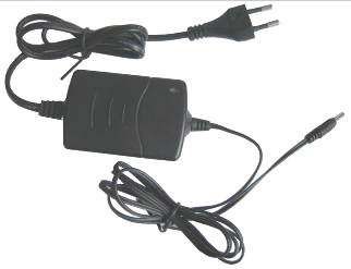
DE

E     EMPFÄNGER FR 45
     BEDIENELEMENTE                                                     11         1
     1. Libelle (2)
     2. Display                                                                    2
     3. Referenzmarke                                                                  4
     4. Empfangsfenster                             3
     5. AN- / AUS-Schalter                                                                 8
     6. Lautsprecher
                                                    11
     7. Batteriefach (Rückseite)                    1
     8. Ton an / aus
     9. Genauigkeit grob / normal / fein
                                                    9
     10. Beleuchtung an / aus                        10                                5
     11. Magnet (2)                                                                            12
     12. 1/4“-Gewinde f. Klammer (Rückseite)                                           6

                                                                        7
     LIEFERUMFANG

     Empfänger FR 45, Batterie, Halteklammer, Bedienungsanleitung

      Technische Daten
      Anzeige                                                       Display vorn
      Genauigkeit grob                                              ± 10 mm
      Genauigkeit normal                                            ± 4 mm
      Genauigkeit fein                                              ± 2 mm
      Signaltöne                                                    3
      Betriebsdauer                                                 400h
      Stromversorgung                                               1 x 9V

     SYMBOLE

     1.   Empfänger an / aus
     2.   Batteriezustandsanzeige
     3.   Empfindlichkeitsindikator
     4.   Ton an / aus
     5.   Empfangsposition Laserstrahl

8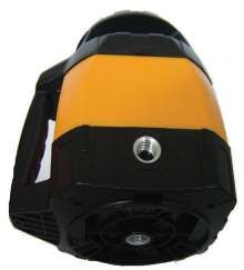
DE

GENAUIGKEITSEINSTELLUNG GROB/ NORMAL / FEIN

Der FR 45 ist mit drei Genauigkeitsstufen ausgestattet. Zur Auswahl Taste (9) drücken:

Genauigkeit grob    ± 10 mm
Displaysymbol: leeres Feld

Genauigkeit normal ± 4 mm
Displaysymbol:

Genauigkeit fein     ± 2 mm
Displaysymbol:

EINLEGEN DER BATTERIE

• Batteriefachdeckel (7) öffnen.
• 1 x 9 V AA Batterie gemäß dem Installationssymbol (auf der Rückseite) einlegen und dabei auf kor-
  rekte Polarität achten. Deckel schließen.
• Zur Verlängerung der Lebensdauer der Batterie schaltet sich der Empfänger nach ca. 5 Min. ohne
  Anwendung automatisch ab.

EINSCHALTEN

Knopf (5) drücken.

Zum Empfangen des Laserstrahls den Empfänger langsam auf und ab
bewegen.

A     Empfänger nach unten bewegen
      Akustisches Signal: schneller Piepton

B     Empfänger nach oben bewegen
      Akustisches Signal: langsamer Piepton

C     Korrekte Bezugshöhe
      Akustisches Signal: Dauerton

A+B: Je mehr man sich der korrekten Bezugshöhe (C) nähert, desto
     kürzer werden die Pfeile.

HALTEKLAMMER FÜR NIVELLIERLATTE

Der Empfänger kann in Verbindung mit der Halteklammer an einer Nivellierlatte oder anderen Gegen-
ständen befestigt werden.

                                                                                                       9
DE
F SICHERHEITSHINWEISE
UMSTÄNDE, DIE DAS MESSERGEBNIS VERFÄLSCHEN KÖNNEN
Messungen durch Glas- oder Plastikscheiben; verschmutzte Laseraustrittsfenster; Sturz oder starker Stoß. Bitte
Genauigkeit überprüfen.
Große Temperaturveränderungen: Wenn das Gerät aus warmer Umgebung in eine kalte oder umgekehrt gebracht wird,
vor Benutzung einige Minuten warten.
UMGANG UND PFLEGE
Messinstrumente generell sorgsam behandeln. Nach Benutzung mit weichem Tuch reinigen (ggfs. Tuch in etwas
Wasser tränken). Wenn das Gerät feucht war, sorgsam trocknen. Erst in den Koffer oder die Tasche packen, wenn es
absolut trocken ist. Transport nur in Originalbehälter oder -tasche.
ELEKTROMAGNETISCHE VERTRÄGLICHKEIT
Es kann nicht generell ausgeschlossen werden, dass das Gerät andere Geräte stört (z.B. Navigationseinrichtungen);
durch andere Geräte gestört wird (z.B. elektromagnetische Strahlung bei erhöhter Feldstärke z.B. in der unmittelbaren
Nähe von Industrieanlagen oder Rundfunksendern).
CE-KONFORMITÄT
Das Gerät hat das CE-Zeichen gemäß den Normen EN 61010-1:2001 + corrig. 1+2.
GARANTIE
Die Garantiezeit beträgt zwei (2) Jahre, beginnend mit dem Verkaufsdatum. Die Garantie erstreckt sich nur auf Mängel
wie Material-oder Herstellungsfehler, sowie die Nichterfüllung zugesicherter Eigenschaften. Ein Garantieanspruch
besteht nur bei bestimmungsgemäßer Verwendung. Mechanischer Verschleiß und äußerliche Zerstörung durch Ge-
waltanwendung und Sturz unterliegen nicht der Garantie. Der Garantieanspruch erlischt, wenn das Gehäuse geöffnet
wurde. Der Hersteller behält sich vor, im Garantiefall die schadhaften Teile instand zusetzen bzw. das Gerät gegen ein
gleiches oder ähnliches (mit gleichen technischen Daten) auszutauschen. Ebenso gilt das Auslaufen der Batterie nicht
als Garantiefall.
HAFTUNGSAUSSCHLUSS
1. Der Benutzer dieses Produktes ist angehalten, sich exakt an die Anweisungen der Bedienungsanleitung zu
halten. Alle Geräte sind vor der Auslieferung genauestens überprüft worden. Der Anwender sollte sich trotzdem
vor jeder Anwendung von der Genauigkeit des Gerätes überzeugen.
2. Der Hersteller und sein Vertreter haften nicht für fehlerhafte oder absichtlich falsche Verwendung sowie daraus
eventuell resultierende Folgeschäden und entgangenen Gewinn.
3. Der Hersteller und sein Vertreter haften nicht für Folgeschäden und entgangenen Gewinn durch Naturkatastro-
phen wie z.B. Erdbeben, Sturm, Flut, usw. sowie Feuer, Unfall, Eingriffe durch Dritte oder einer Verwendung
außerhalb der üblichen Einsatzbereiche.
4. Der Hersteller und sein Vertreter haften nicht für Schäden und entgangenen Gewinn durch geänderte oder
verlorene Daten, Unterbrechung des Geschäftsbetriebes usw., die durch das Produkt oder die nicht mögliche
Verwendung des Produktes verursacht wurden.
5. Der Hersteller und sein Vertreter haften nicht für Schäden und entgangenen Gewinn resultierend aus einer nicht
anleitungsgemäßen Bedienung.
6. Der Hersteller und sein Vertreter haften nicht für Schäden, die durch unsachgemäße Verwendung oder in Verbin-
dung mit Produkten anderer Hersteller verursacht wurden.
10DE
BESTIMMUNGSGEMÄSSE VERWENDUNG
Das Gerät sendet einen sichtbaren Laserstrahl aus, um z.B. folgende Messaufgaben durchzuführen: Ermittlung von
Höhen; rechten Winkeln, Ausrichtung von horizontalen und vertikalen Bezugsebenen (je nach Gerät).
WARN- UND SICHERHEITSHINWEISE
· Richten Sie sich nach den Anweisungen der Bedienungsanleitung.
· Anleitung vor Benutzung des Gerätes lesen.
· Blicken Sie niemals in den Laserstrahl, auch nicht mit optischen Instrumenten. Es besteht die Gefahr von Augen-
schäden.
· Laserstrahl nicht auf Personen richten.
· Die Laserebene soll sich über der Augenhöhe von Personen befinden.
· Niemals das Gehäuse öffnen. Reparaturen nur vom autorisierten Fachhändler durchführen lassen.
· Keine Warn- oder Sicherheitshinweise entfernen.
· Lasergerät nicht in Kinderhände gelangen lassen.
· Gerät nicht in explosionsgefährdeter Umgebung betreiben.
· Diese Gebrauchsanleitung ist aufzubewahren und bei Weitergabe der Lasereinrichtung mitzugeben.
LASERKLASSIFIZIERUNG
Das Gerät entspricht der Lasersicherheitsklasse 2 gemäß der Norm DIN IEC 60825-1:2014.
Das Gerät darf ohne weitere Sicherheitsmaßnahmen eingesetzt werden.
Das Auge ist bei zufälligem, kurzzeitigem Hineinsehen in den Laserstrahl durch den Lidschlussreflex geschützt.
Laserwarnschilder der Klasse 2 sind gut sichtbar am Gerät angebracht.
www.geo-fennel.de
Laser
2
IEC 60825-1:2014
P ≤ 1 mW @ 635 - 670 nm
Bitte unbedingt beachten:
Wenn Sie Geräte zur Reparatur / zur Justage an uns zurücksenden, entnehmen Sie bitte unbedingt aus
Sicherheitsgründen Akkus oder Batterien aus dem Gerät!
Danke.
11EN
Dear customer,
Thank you for your confidence in us having purchased a geo-FENNEL instrument.
This manual will help you to operate the instrument appropriately.
Please read the manual carefully - particularly the safety instructions. A proper use only guarantees a
longtime and reliable operation.
geo-FENNEL
Precision by tradition.
Contents
1. Supplied with A
2. Features B
3. Power supply C
4. Keypad and operation D
5. Receiver E
6. Safety notes F
A SUPPLIED WITH
· Rotating Laser FL 220HV
· Receiver FR 45 with clamp for levelling
staff
· Rechargeable battery and charger
· Battery case for Alkaline batteries
· Carrying case
· User manual
12EN
CHARACTERISTICS
· Working range up to 400 m Ø
· Dust / water protection IP 54
· Permanent 90° plumb beam
· Automatic TILT alarm function
· Auto-shut-off when out of level
· Manual mode
Technical data
Self-levelling horizontal / vertical
Self-levelling range ± 5°
Laser class 2
Accuracy
· horizontal ± 1,0 mm / 10 m
· vertical ± 1,5 mm / 10 m
Working range with FR 45 Ø 400 m
Permanent 90° plumb beam yes
TILT mode yes
Manual mode yes
Rotating speed 600 rpm
Power supply / operating time 20 h (NiMH)
Temperature range -20°C - +50°C
Dust / water protection IP 54
13EN
B POWER SUPPLY
Both the standard NiMH battery pack and Alkaline batteries can be used.
1) Insert Alkaline batteries into the Alkaline battery box (ensure correct polarity) and mount the battery
box into the instrument.
OR
2) Mount the rechargeable battery box into the instrument.
1) 2)
CHARGING THE BATTERY
Connect the charger with the charging plug of the instrument and the power source. If the charging
LED is red the battery is being charged; if the LED is green the battery is fully charged.
ATTENTION
The rechargeable battery can be charged if it is in the instrument or if it is ouside.
Battery status indication: If the ON/OFF LED flashes the battery has to be recharged.
Charging LED
14EN
FEATURES C
1. Laser emitting window 1 2
2. Rotating head
3. Handle
4. Battery compartment
5. Keypad
6. Support for vertical use
7. 5/8“ thread hole vertical 5 3
8. 5/8“ thread hole horizontal
9. Charging plug
6 4
9
5/8″
7
8 5/8″
OPERATION D
HORIZONTAL USE
Set up the instrument on an even surface or mount it onto a tripod.
VERTICAL USE
Set up the instrument vertically (on the side with the vertical 5/8“ hole) or mount it onto a tripod with
its vertical 5/8“ thread.
15EN
HORIZONTAL USE
After powering on the unit a flashing laser diode indicates that the automatic self-levelling procedure is
working. The laser starts rotating when it is self-levelled. If not the laser was set up outside of its self-
levelling range. In this case set up the instrument on a more even surface.
1. ON/OFF button
2. ON/OFF LED
3. MANUAL button
4. MANUAL LED
5. TILT LED
1 6. TILT button
2
6 3
5 4
POWER ON/OFF (1)
Power the laser on/off with button (1). If the red ON/OFF LED (2) is illuminated the laser is powered on.
First the laser dot is flashing, then the self-levelling procedure starts automatically; meanwhile the TILT
LED (5) is flashing. When the self-levelling procedure is completed the laser rotates with 600 rpm and
the TILT LED (5) is illuminated permanently (= TILT function activated).
If in normal use the ON/OFF LED (1) flashes the battery has to be recharged.
TILT MODE (6)
After completion of the self-levelling procedure the TILT mode is automatically enabled.
If the level is now disturbed the rotation stops and the TILT LED is flashing.
1. Press the TILT button (6) once: The rotation of the laser starts - but the TILT mode is disabled.
2. Press the TILT button (6) twice: The rotation of the laser starts, the self-levelling procedure is
completed and the laser restarts working with enabled TILT mode.
Press button (6) to disable the TILT mode after completion of the self-levelling procedure.
16EN
MANUAL MODE (3)
Power on the laser with button (1). After completion of the self-levelling procedure press button (3).
The TILT LED (5) will power off and the MANUAL LED (4) will be illuminated permanently. Now the
laser can be used in slope position, i. e. it can be used with a grade mount without giving TILT alarm.
In vertical position a required alignment can be made quick and safe by means of the MAN function.
When the alignment has been made quit the MAN function.
APPLICATION
17EN
E RECEIVER FR 45
FEATURES 11 1
1. Vial (2)
2. Display 2
3. Reference indicator 4
4. Receiving window 3
5. ON / OFF switch 8
6. Loudspeaker
11
7. Battery compartment (back side) 1
8. Sound on / off
9. Accuracy coarse / normal / fine
9
10. Light on / off 10 5
11. Magnets (2) 12
12. 1/4“-thread for clamp (back side) 6
7
SUPPLIED WITH
Receiver FR 45, battery, clamp, user manual
Technical Data
Indication Front display
Accuracy coarse ± 10 mm
Accuracy normal ± 4 mm
Accuracy fine ± 2 mm
Tones 3
Operating time 400h
Power supply 1 x 9V
SYMBOLS
1. Power ON / OFF
2. Battery status indicator
3. Detection indicator
4. Sound ON / OFF
5. Detected position indicator
18EN
ACCURACY COARSE / NORMAL / FINE
The FR 45 is equipped with three precision modes. They can be chosen by pressing button (9):
Accuracy coarse ± 10 mm
Symbol on display: without symbol
Accuracy normal ± 4 mm
Symbol on display:
Accuracy fine ± 2 mm
Symbol on display:
INSTALLATION OF THE BATTERIES
• Open the battery compartment cover (7).
• Insert 1 x 9 V AA battery according to the installation symbol (ensure correct polarity!). Close the
cover.
• In order to save battery power the receiver will automatically turn off if it has not received laser scan-
ning singal for 5 minutes.
USE OF RECEIVER
Press the button (5) to switch the unit on.
Move the receiver up and down carefully to detect the laser beam.
A Move the receiver down
Acoustic signal : ultra-short requent beep
B Move the receiver up
Acoustic signal: short requent beep
C On level
Acoustic signal: continuous beep
A+B: The closer the distance to „on level“ (C) is,
the shorter the arrows become.
CLAMP FOR LEVELLING STAFF
If required the FR 45 can be attached to laser poles or any other equipment by means of the clamp
supplied with.
19EN
F SAFETY NOTES
SPECIFIC REASONS FOR ERRONEOUS MEASURING RESULTS
Measurements through glass or plastic windows; dirty laser emitting windows; after the instrument has been dropped
or hit. Please check the accuracy.
Large fluctuation of temperature: If the instrument will be used in cold areas after it has been stored in warm areas (or
the other way round) please wait some minutes before carrying out measurements.
CARE AND CLEANING
Handle measuring instruments with care. Clean with soft cloth only after any use. If necessary damp the cloth with
some water. If the instrument is wet clean and dry it carefully. Pack it up only if it is perfectly dry. Transport in original
container / case only.
ELECTROMAGNETIC ACCEPTABILITY (EMC)
It cannot be completely excluded that this instrument will disturb other instruments (e.g. navigation systems); will be
disturbed by other instruments (e.g. intensive electromagnetic radiation nearby industrial facilities or radio transmit-
ters).
CE-Conformity
The instrument has the CE mark according to EN 61010-1:2001 + corrig. 1+2.
WARRANTY
This product is warranted by the manufacturer to the original purchaser to be free from defects in material and
workmanship under normal use for a period of two (2) years from the date of purchase. During the warranty period,
and upon proof of purchase, the product will be repaired or replaced (with the same or similar model at manufacturers
option), without charge for either parts or labour. In case of a defect please contact the dealer where you originally
purchased this product. The warranty will not apply to this product if it has been misused, abused or altered. Without
limiting the foregoing, leakage of the battery, bending or dropping the unit are presumed to be defects resulting from
misuse or abuse.
EXCEPTIONS FROM RESPONSIBILITY
1. The user of this product is expected to follow the instructions given in the user manual. Although all instruments
left our warehouse in perfect condition and adjustment the user is expected to carry out periodic checks of the
product’s accuracy and general performance.
2. The manufacturer, or its representatives, assumes no responsibility of results of a faulty or intentional usage or
misuse including any direct, indirect, consequential damage, and loss of profits.
3. The manufacturer, or its representatives, assumes no responsibility for consequential damage, and loss of profits
by any disaster (earthquake, storm, flood etc.), fire, accident, or an act of a third party and/or a usage in other
than usual conditions.
4. The manufacturer, or its representatives, assumes no responsibility for any damage, and loss of profits due to
a change of data, loss of data and interruption of business etc., caused by using the product or an unusable
product.
5. The manufacturer, or its representatives, assumes no responsibility for any damage, and loss of profits caused
by usage other than explained in the user manual.
6. The manufacturer, or its representatives, assumes no responsibility for damage caused by wrong movement or
action due to connecting with other products.
20EN
INTENDED USE OF INSTRUMENT
The instrument emits a visible laser beam in order to carry out the following measuring tasks (depending on the instru-
ment): Setting up heights, horizontal and vertical planes, right angles.
SAFETY INSTRUCTIONS
· Follow up the instructions given in the user manual.
· Do not stare into the beam. The laser beam can lead to eye injury. A direct look into the beam (even from greater
distance) can cause damage to your eyes.
· Do not aim the laser beam at persons or animals.
· The laser plane should be set up above the eye level of persons.
· Use the instrument for measuring jobs only.
· Do not open the instrument housing. Repairs should be carried out by authorized workshops only. Please contact
your local dealer.
· Do not remove warning labels or safety instructions.
· Keep the instrument away from children.
· Do not use the instrument in explosive environment.
· The user manual must always be kept with the instrument.
LASER CLASSIFICATION
The instrument is a laser class 2 laser product according to DIN IEC 60825-1:2014.
It is allowed to use the unit without further safety precautions.
The eye protection is normally secured by aversion responses and the blink reflex.
The laser instrument is marked with class 2 warning labels.
www.geo-fennel.de
Laser
2
IEC 60825-1:2014
P ≤ 1 mW @ 635 - 670 nm
Please note:
If you return instruments for repair / for adjustment to us please disconnect batteries or rechargeable batteries
from the instrument - this is for safety reasons!
Thank you.
21FR
Cher client,
Nous tenons à vous remercier pour la confiance que vous avez témoignée, par l‘acquisition de votre
nouvel instrument geo-FENNEL.
Les instructions de service vous aideront à vous servir de votre instrument de manière adéquate. Nous
vous recommandons de lire avec soin tout particulièrement les consignes de sécurité de ladite notice
avant la mise en service de votre appareil. Un emploi approprié est l‘unique moyen de garantir un fonc-
tionnement efficace et de longue durée.
geo-FENNEL
Precision by tradition.
Contenu
1. Livré comme suit A
2. Alimentation en courant B
3. Descriptif C
4. Opération D
5. Cellule de réception E
6. Consignes de sécurité F
A LIVRÉ COMME SUIT
· Laser rotatif FL 220HV
· Cellule de réception FR 45 avec son
support
· Accu et chargeur
· Bloc piles de secours
· Coffret
· Mode d‘emploi
22FR
FONCTIONS
· Portée de 400 m Ø
· Étanchéité IP 54
· Point d‘equerrage permanent à 90°
· Fonction TILT
· Arrêt du laser si il n‘est pas de niveau
· Fonction manuelle
Données techniques
Auto-nivellement horizontal / vertical
Plage d‘autonivellement ± 5°
Classe de laser 2
Précision
· horizontale ± 1,0 mm / 10 m
· verticale ± 1,5 mm / 10 m
Portée avec FR 45 Ø 400 m
Point d‘equerrage permanent à 90° oui
Mode TILT oui
Mode manuel oui
Vitesse de rotation 600 trs
Alimentation / autonomie 20 h (NiMH)
Plage de température -20°C - +50°C
Étanche aux poussieres / eaux IP 54
23FR
B ALIMENTATION EN COURANT
L’instrument laser est équipé d’une batterie d’accumulateurs. Comme solution de rechange, il peut
fonctionner avec des piles alcalines.
1) Mettez en place les piles alcalines dans le logement prévu à cet effet (faites attention à la pola-
rité) et insérez ledit logement dans l’instrument.
OU
2) Insérez la batterie d’accumulateurs rechargeables type NiMH dans l’instrument.
CHARGER LES ACCUS
Reliez la douille du chargeur d’accus à l’instrument et l’autre câble au réseau. L’opération de charge est
en cours tant que la diode de charge est allumée en rouge et elle est achevée dès que ce voyant passe
au vert.
ATTENTION
Les accumulateurs peuvent être chargés soit lorsqu’ils sont insérés dans l’instrument, soit hors de
l’instrument.
Lorsque la diode MARCHE / ARRÊT située sur l’instrument commence à clignoter, il faut recharger les
accumulateurs.
Diode de charge
24FR
DESCRIPTIF C
1. Fenêtre de sortie du faisceau laser 1 2
2. Tête du laser
3. Poignée
4. Logement de piles
5. Clavier
6. Point d‘appui pour une opération verticale
7. 5/8“-pas de vis verticale 5 3
8. 5/8“-pas de vis horizontale
9. Douille pour chargeur d‘accus
6 4
9
5/8″
7
8 5/8″
OPÉRATION D
EMPLOI AVEC FAISCEAU HORIZONTAL
Placer l’instrument sur une surface à peu près horizontale ou sur un trépied.
EMPLOI AVEC FAISCEAU VERTICAL
Placer l’instrument avec le faisceau à la verticale (filetage se trouvant sur le côté) ou fixer son filetage
vertical sur un trépied.
25FR
Après la mise en marche, l’instrument se met à niveau automatiquement (la trace ponctuelle du
laser clignote). La tête rotative commence à tourner dès que la phase d’autonivellement est ache-
vée. Si l’autonivellement n’a pas lieu, cela signifie que l’instrument se trouve hors de la plage
d’autonivellement. Placez à nouveau l’instrument sur une surface plus horizontale.
1. Touche MARCHE/ARRÊT
2. Diode MARCHE/ARRÊT
3. Touche mode manuel
4. Diode mode manuel
5. Diode TILT
1 6. Touche mode TILT
2
6 3
5 4
METTRE L‘INSTRUMENT EN MARCHE/ARRÊT (1)
Pressez la touche (1) pour mettre l‘instrument en MARCHE/ARRÊT. Quand la diode marche/arrêt (2)
est allumée l‘instrument est en marche. D‘abord le point laser clignote, puis la mise à niveau automa-
tique a lieu. Pendant ce temps la diode TILT (5) clignote. Quand la mise à niveau est achevée le laser
commence à tourner à 600 trs et la diode TILT (5) est allumée en permanence (= mode TILT activé).
Si la diode marche/arrêt (2) commence à clignoter en fonction normale il faut alors recharger l‘accu.
MODE TILT (6)
Après la mise à niveau du laser le mode TILT est activé automatiquement.
Un changement de position aura maintenant comme effet l‘arrêt de la rotation; la diode TILT clignotera.
1. Pressez la touche TILT (6) une fois: La rotation du laser recommence - mais le mode TILT est mai-
nenant inactif.
2. Pressez la touche TILT (6) deux fois: La rotation du laser recommence, la mise de niveau automa-
tique a lieu et l‘instrument retravaillera avec le mode TILT activé.
Pour mettre le mode TILT inactif après la mise à niveau pressez la touche TILT (6).
26FR
MODE MANUEL (3)
Mettez l‘instrument en marche avec la touche (1), attendez la mise de niveau automatique et quand
celle-ci est achevée pressez la touche MANUEL (3). La diode TILT (5) s‘éteint, la diode MANUEL (4)
s‘allume. Maintenant le laser peut travailler dans toutes les positions sans déclencher l‘alarme TILT.
Utilisant la fonction MANUEL en position verticale vous pouvez procéder à un alignement désiré
rapidement et fiablement.
Après avoir fini l‘alignement quittez cette fonction.
EXEMPLES D‘APPLICATION
27FR
E CELLULE FR 45
DESCRIPTION 11 1
1. Nivelle (2)
2. Écran 2
3. Hauteur de référence 4
4. Fenêtre de réception 3
5. Bouton marche/arrêt 8
6. Haut-parleur
11
7. Logement de piles 1
8. Son marche/arrêt
9. Précision fine / normale / grossière
9
10. Éclairage marche/arrêt 10 5
11. Aimant (2) 12
12. Filetage ¼” pour le support de cellule 6
LIVRÉ COMME SUIT 7
Cellule FR 45, support de cellule, pile, mode d‘emploi
Données techniques
Affichage Écran
Précision grossière ± 10 mm
Précision normale ± 4 mm
Précision fine ± 2 mm
Son signal 3 plages
Durée de marche 400h
Alimentation en courant 1 x 9V
SYMBOLE
1. Cellule ON / OFF
2. Indication de l‘état des piles
3. Indicateur de sensibilité
4. Son ON / OFF
5. Position de réception du faisceau laser
28FR
RÉGLAGE DE LA PRÉCISION FINE / NORMALE / GROSSIÈRE
Le FR 45 est équipé de trois niveaux de précision. Pour choisir, pressez bouton (9):
Précision grossière ± 10 mm
Symbole sur l‘écran: champ vide
Précision normale ± 4 mm
Symbole sur l‘écran:
Précision fine ± 2 mm
Symbole sur l‘écran:
MISE EN PLACE DES PILES
• Ouvrir le couvercle du logement des piles (7).
• Mettre en place une pile de bloc 9 V, conformément au symbole d‘installation (sur la face posté-
• rieure), en veillant à la polarité correcte. Fermer le couvercle.
• En cas de non-utilisation, la cellule s‘arrête automatiquement après 5 min. env., afin de prolonger la
durée de vie des piles.
TRAVAIL SUR DÉTECTEUR
Presser le bouton (5).
Pour capter le faisceau laser, faire monter et descendre lentement
la cellule.
A Déplacer la cellule vers le bas.
Signal acoustique: Bipe sonore rapide
B Déplacer la cellule vers le haut.
Signal acoustique: Bipe sonore lent
C Hauteur de référence correcte
Signal acoustique: son continu
A+B: Les flèches deviennent d‘autant plus courtes que l‘on se rapproche
davantage de la hauteur de référence correcte (C)
SUPPORT DE CELLULE POUR MIRE DE NIVELLEMENT
Il est possible de fixer la cellule sur la mire de nivellement ou d‘autres objets, à l‘aide du support de
cellule.
29FR
F CONSIGNES DE SÉCURITÉ
CIRCONSTANCES POUVANT FAUSSER LES RÉSULTATS DE MESURES
Mesures effectuées à travers des plaques de verre ou de matière plastique; mesures effectuées à travers la fenêtre
de sortie du faisceau laser lorsqu‘elle est sale. Mesures après que le niveau soit tombé ou ait subi un choc très fort.
Mesures effectuées pendant de grandes différences de température - p. ex. lorsque l‘instrument passe rapidement
d‘un milieu très chaud à un autre très froid; attendre alors quelques minutes d‘adaptation avant de réutiliser le niveau.
NETTOYAGE ET REMISAGE
Essuyer l‘instrument mouillé, humide ou sali en le frottant uniquement avec un tissu de nettoyage. Quant à l‘optique,
la nettoyer avec un tissu fin comme p. ex. un tissu feutré de lunettes.
Ne jamais mettre un instrument humide dans un coffret fermé! Le laisser sécher auparavant au moins pendant un jour
dans un local chauffé! Transport seulement dans le coffret original.
COMPATIBILITÉ ÉLECTROMAGNÉTIQUE
De manière générale, il n‘est pas exclu que le niveau ne dérange d‘autres instruments (p. ex. les dispositifs de navigati-
on) ou qu‘il puisse lui-même être dérangé par d‘autres appareils (p. ex. soit par un rayonnement électromagnétique dû à
une élévation de l‘intensité du champ, soit par la proximité d‘installations industrielles ou d‘émetteurs de radiodiffusion).
CONFORMITÉ CE
Le niveau porte le label CE conformément aux normes NE 61010-1:2001.
GARANTIE
La durée de garantie est de deux (2) ans à partir de la date d‘achat. Cette garantie ne couvre que les défauts tels
que le matériel défectueux ou les anomalies de fabrication, ainsi que le manque des propriétés prévues. Le droit à la
garantie n‘est valable que si l‘utilisation du niveau a été conforme aux préscriptions. En sont exclus l‘usure mécanique
et un endommagement externe par suite d‘usage de la force et/ou d‘une chute. Le droit à la garantie prend fin lorsque
le boîtier a été ouvert. Dans un cas couvert par la garantie, le fabricant se réserve le droit de remettre en état les
éléments défectueux ou d‘échanger l‘instrument par un autre identique ou similaire (possédant les mêmes caracté-
ristiques techniques). De même, un endommagement résultant d‘un écoulement de l‘accumulateur n‘est pas couvert
par la garantie.
UTILISATION CONFORME AUX PRÉSCRIPTIONS
Le niveau projette un faisceau laser visible, pour effectuer p. ex. les travaux de mesures suivants: détermination de
l‘hauteur, tracé d’angles droits, pointage de plans de référence horizontaux ainsi qu’obtention de points d’aplomb
(dépendant de l‘instrument).
Merci de respecter le suivant impérativement:
Si vous retournez des instruments pour réparation / ajustage vous devez - pour des raisons de sécurité -
impérativement enlever les accus.
Merci.
30FR
EXCLUSION DE LA RESPONSABILITÉ
1. L‘utilisateur de ce produit est tenu de respecter ponctuellement les instructions du mode d‘emploi.
Tous les instruments ont été très soigneusement vérifiés avant leur livraison. Toutefois, l‘utilisateur
devra s‘assurer de la précision de ce niveau avant chaque emploi.
2. Le fabricant et son représentant déclinent toute responsabilité dans le cas d‘utilisation incorrecte ou
volontairement anormale ainsi que pour les dommages consécutifs en découlant, tout comme pour
les bénéfices non réalisés.
3. Le fabricant et son représentant déclinent toute responsabilité pour les dommages consécutifs et
les bénéfices non réalisés par suite de catastrophes naturelles, comme p. ex. tremblement de terre,
tempête, raz de marée etc. ainsi que d‘incendie, accident, intervention malintentionnée d‘une tierce
personne, ou encore dus à une utilisation hors du domaine d‘application normal de l‘instrument.
4. Le fabricant et son représentant déclinent toute responsabilité pour les dommages et les bénéfices
non réalisés par suite de modification ou perte de données, interruption du travail de l‘entreprise
etc., à savoir les dommages qui découlent du produit lui-même ou de la non-utilisation du produit.
5. Le fabricant et son représentant déclinent toute responsabilité pour les dommages et le bénéfices
non réalisés par suite d‘une manoeuvre non conforme aux instructions.
6. Le fabricant et son représentant déclinent toute responsabilité pour les dommages et les bénéfices
non réalisés qui decoulent d‘une utilisation inadéquante ou en liaison avec des produits d‘autres
fabricants.
INDICATIONS D‘AVERTISSEMENT ET DE SÉCURITÉ
· Prière de respecter les instructions fournies dans le mode d’emploi de l‘instrument.
· Lire ces instructions avant d’utiliser l’instrument.
· Ne jamais regarder le faisceau laser, même pas avec un appareil optique, à cause du risque de lési-
ons oculaires pouvant en résulter.
· Ne pas diriger le faisceau laser sur une personne.
· Le plan du faisceau laser doit se trouver à hauteur des yeux de l’opérateur.
· Ne jamais ouvrir soi-même le boîtier du niveau.
· Faire exécuter les réparations éventuelles uniquement par un spécialiste autorisé.
· Ne pas enlever les indications d’avertissement et de sécurité portées sur le niveau
· Éviter que l’instrument ne soit touché ou manipulé par des enfants
· Ne pas utiliser le laser dans un milieu à risque d’explosions.
CLASSIFICATION DES LASERS
Ce niveau correspond à la classe de sécurité des lasers 2, conformément à la norme DIN EN 60825-1:2014. De ce fait,
l’instrument peut être utilisé sans avoir recours à d’autres mesures de sécurité. Au cas où l’utilisateur a regardé un
court instant le faisceau laser, les yeux sont tout de même protégés par le réflexe de fermeture des paupières.
Les pictogrammes de danger de la classe 2 sont bien visibles sur le niveau.
www.geo-fennel.de
Laser
2
IEC 60825-1:2014
P ≤ 1 mW @ 635 - 670 nm
31geo-FENNEL GmbH
Technische Änderungen vorbehalten.
Kupferstraße 6 All instruments subject to technical changes.
D-34225 Baunatal Sous réserve de modifications techniques.
Tel. +49 561 / 49 21 45
Fax +49 561 / 49 72 34
info@geo-fennel.de 10/2019
www.geo-fennel.de
Precision by tradition.Sie können auch lesen