Geo6-XR GREEN SP BEDIENUNGSANLEITUNG USER MANUAL MODE D'EMPLOI - geo-FENNEL
←
→
Transkription von Seiteninhalten
Wenn Ihr Browser die Seite nicht korrekt rendert, bitte, lesen Sie den Inhalt der Seite unten
DE | EN | FR

         Geo6-XR GREEN SP

BEDIENUNGSANLEITUNG
USER MANUAL
MODE D‘EMPLOI

                www.geo-fennel.com
DE

     Sehr geehrter Kunde,

     vielen Dank für das Vertrauen, welches Sie uns beim Erwerb Ihres neuen geo-FENNEL-Gerätes
     entgegengebracht haben. Dieses hochwertige Qualitätsprodukt wurde mit größter Sorgfalt produziert
     und qualitätsgeprüft.

     Die beigefügte Anleitung wird Ihnen helfen, das Gerät sachgemäß zu bedienen. Bitte lesen Sie ins-
     besondere auch die Sicherheitshinweise vor der Inbetriebnahme aufmerksam durch. Nur ein sachge-
     rechter Gebrauch gewährleistet einen langen und zuverlässigen Betrieb.

     geo-FENNEL
     Precision by tradition.

      Inhaltsverzeichnis
      1. Lieferumfang                                                                              A
      2. Stromversorgung                                                                           B
      3. Bedienelemente                                                                            C
      4. Bedienung                                                                                 D
      5. Sicherheitshinweise                                                                       E

A         LIEFERUMFANG
     ··   Linienlaser Geo6-XR GREEN SP
     ··   Li-Ion Akku
     ··   Ladegerät + USB 3.0-Kabel
     ··   Batteriefach für Alkalinebatterien
     ··   Höhenverstellbare Plattform
     ··   Wandhalterung
     ··   Verbindungsschiene
     ··   20 mm-Adapter mit 5/8“
     ··   3 Höhenprüfpins
     ··   Magnetische Zieltafel
     ··   Koffer
     ··   Bedienungsanleitung

2
DE

EIGENSCHAFTEN

·· 3 x 360°-Laserlinien
   => bilden 6 Laserkreuze
·· Laserlinien einzeln schaltbar
·· Lotfunktion
·· Minimaler Abstand der Laserebene zum Boden 8 mm
·· Minimaler Abstand der Laserebene zur Wand 6 mm
·· Höhenverstellbare Plattform im Bereich von 25 bis 85 mm
·· Wandhalterung
·· - höhen- und seitenverstellbar
·· - für Wandhängung mittels Schraube/Nagel
·· - Befestigung an magnetischen Flächen
·· - zur Riemenbefestigung
·· Optisches Warnsignal wenn ausserhalb des Selbstnivellierbereiches
·· Manuellfunktion zur Schräganwendung
·· Stativanschluss 5/8“ (Geräteunterseite / mit Adapter)
·· Stativanschluss 1/4"
·· Einsatz mit Empfänger (optional)

 Technische Daten
 Selbstnivellierbereich                                        ± 3°
 Genauigkeit                                                   ± 2 mm / 10 m
 Arbeitsbereich
 ·· ohne Empfänger                                             40 m* (Radius)
 ·· mit Empfänger (optional)                                   60 m** (Radius)
 Stromversorgung / Betriebsdauer
 ·· 1 x 360°                                                   15 h / Li-Ion
 ·· 2 x 360°                                                   7 h / Li-Ion
 ·· 3 x 360°                                                   5 h / Li-Ion
 Staub-/Wasserschutz                                           IP 54
 Laserdiode / Laserklasse                                      grün / 2
 Temperaturbereich                                             -10°C - +45°C
 Abmessungen                                                   115 x 96 x 118 mm
 Gewicht (Gerät mit Akku)                                      0,8 kg
*abhängig von der Raumhelligkeit
**abhängig von der Ausrichtung des Lasers

                                                                                   3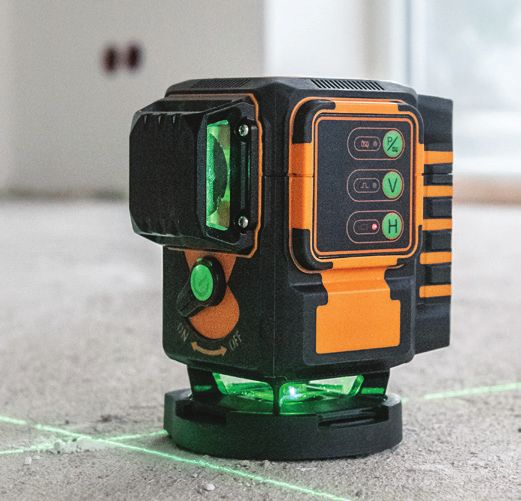
DE

B     STROMVERSORGUNG
     ALKALINEBATTERIEN
     Batteriefachdeckel am Gerät (4) öffnen und
     Box für Alkalinebatterien entnehmen. Alkaline-
     batterien einlegen (korrekte Polarität beachten)
     und Box wieder einsetzen. Batteriefachdeckel
     schließen. Wenn die AN/AUS-LED blinkt, Batte-
     rien gegen neue austauschen (kompletten Satz)
     oder Akku laden.

     AKKU
     Batteriefachdeckel (4) öffnen und Akkupack
     einlegen. Batteriefachdeckel wieder schließen.

     Zum Laden den Akku aus dem Gerät
     entnehmen und außerhalb des Gerätes laden.
     Nach dem Laden den Akku wieder einsetzen.

     Die AN/AUS-LED ist gleichzeitig auch Batte-
     riezustandsanzeige. Sie fängt an zu blinken,
     wenn die Batteriespannung zu schwach ist.

     Der Ladezustand wird am Ladegerät angezeigt:

     Permanentes rotes Licht zeigt an, dass der
     Akkupack geladen wird.
     Permanentes grünes Licht zeigt an, dass der
     Ladevorgang abgeschlossen ist.

     Das Ladegerät dient auch als Dauerstrom-
     versorgung. Der Anschluss erfolgt über die
     aussenliegende Buchse.

     Der Akku wird hierüber nicht geladen!

4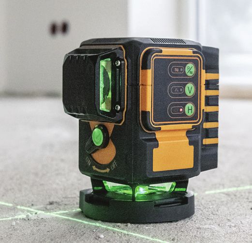
DE
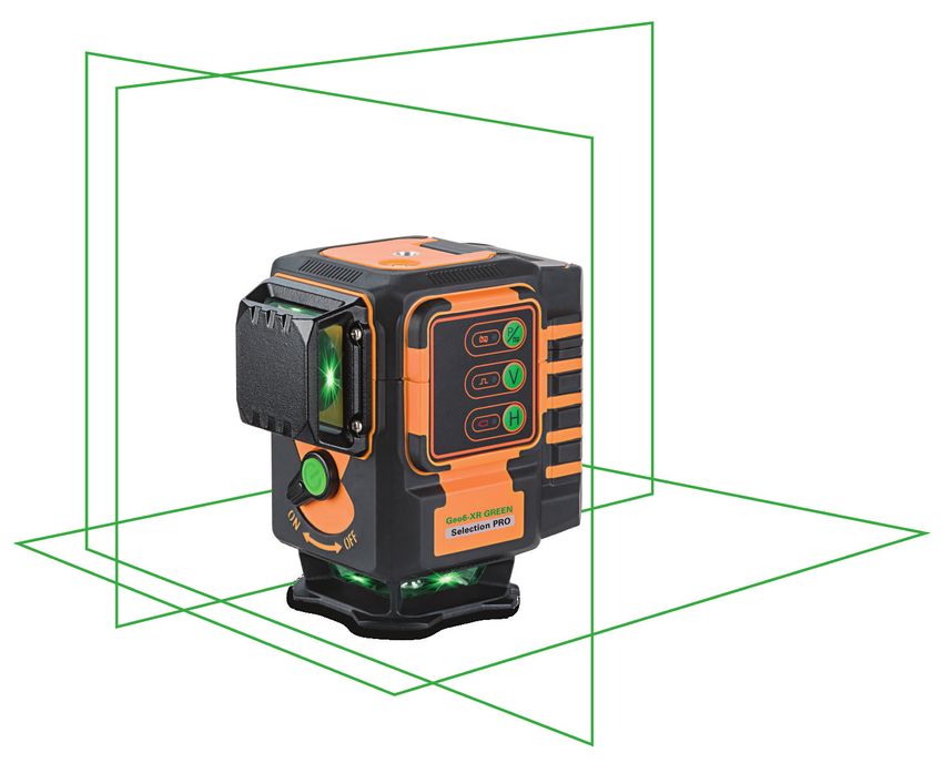
BEDIENELEMENTE C
1. 1/4“-Gewinde
2. Libelle
3. Tastatur 1
2
4. Batteriefachdeckel 4
5. Anschluss für Dauerstromversorgung
über das Ladegerät
6. Laserausgangsfenster
7. AN-/AUS-Schalter / Entriegelungshebel
(Transportsicherung)
6
3
7
5
6
Empfängerbetrieb /
Manuell-
Manuellfunktion
LED
Empfangs-LED vertikale Linie V
AN-/AUS-LED horizontale Linie H
5
DE

     ZUBEHÖRE

     Höhenverstellbare Plattform

     ·· individuell höhenverstellbare Plattform
        im Bereich von 25 bis 85 mm; für höhen-
        korrekte Verlegung von Bodenfliesen
        und Riemchenfliesen                                     rutschfeste
                                                  Höhen-        Oberfläche
                                                  verstellung

     Wandhalterung

     ·· höhenverstellbar mit schwenkbarer
        Halteschiene

     Verbindungsschiene

     ·· frei hängende Befestigung am Stativ
        für beste Liniendarstellung am Boden;
        frei im Raum drehbar

6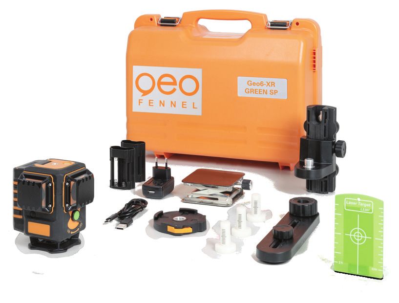
DE

20 mm-Adapter mit 5/8“

·· für den Aufbau auf dem Boden
·· für den Stativanschluss 5/8“
·· fixe Höhe: 20 mm von der Unter-
   kante zur Laserebene

Höhenprüfpins

·· Überprüfung von Bodenunebenheiten
   mittels Höhenkontrollpins

·· Horizontal und vertikal Nivellieren mit 3 x 360° grünen Laserlinien
·· Erstellung rechter Winkel am Boden überall frei im Raum für
   Gerade- und Diagonalverlegung von Fliesen
·· Erstellung und Überprüfung der korrekten Höhe des Bodenbelags
·· Überprüfung der Ebenheit an Wand und Boden

                                                                         7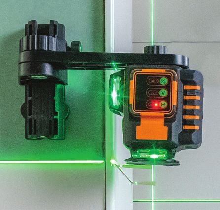
DE

D         BEDIENUNG
     Gerät aufstellen:

     ··   auf den 20 mm-Adapter aufklicken und auf dem Boden ausrichten
     ··   auf den 20 mm-Adapter aufklicken und auf einem Stativ befestigen
     ··   mit der im Lieferumfang enthaltenen höhenverstellbaren Plattform auf dem Boden ausrichten
     ··   mit der Verbindungsschiene an einem Stativ befestigen
     ··   mit den Magneten der Wandhalterung an einer magnetischen Fläche befestigen
     ··   mit dem Loch der Wandhalterung an einer Schraube aufhängen
     ··   mit der Riemenhalterung an einer Säule befestigen
     ··   direkt auf dem Boden aufstellen

     ·· Minimaler Abstand der Laserebene zum Boden 8 mm
     ·· Minimaler Abstand der Laserebene zur Wand 6 mm

     EINSCHALTEN

     AN/AUS-Schalter in Position ON drehen. Das Gerät ist nun betriebsbereit. Steht das Gerät zu schräg
     (außerhalb des Selbstnivellierbereiches), ertönt ein akustisches Warnsignal. Eingeschaltete Laserlinien
     blinken als zusätzliche Warnung.

     Zum Ausschalten AN/AUS-Knopf wieder in Position OFF
     drehen. Das Gerät ist nun ausgeschaltet.

     MERKE:
     Bevor das Gerät in den Koffer gepackt wird, AN/AUS-
     Knopf immer in Position OFF stellen! Ein akustisches
     Warnsignal ertönt, wenn dies einmal übersehen wurde.

8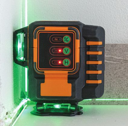
DE

SCHALTBARE
LASERLINIEN

MANUELL-FUNKTION

Wenn sich das Gerät in OFF-Position befindet, Taste MANUELLfunktion einmal drücken, um die
MANUELL-Funktion einzuschalten; die AN/AUS-LED leuchtet, die MANUELL-LED blinkt. Nun kann das
Gerät auch schräg eingesetzt werden; der Kompensatoralarm ist aus. Alle Linien können nun wie im
Standardmodus geschaltet werden. Mit Taste Laserlinie MANUELL-Funktion auch wieder ausschalten.

EMPFÄNGERBETRIEB

Der Geo6-XR GREEN SP kann zur Verlängerung des Arbeitsbereiches oder bei Einsatz unter un-
günstigen Lichtverhältnissen mit einem Empfänger eingesetzt werden. Der Empfänger ist optional
erhältlich (nicht im Lieferumfang enthalten).

Gewünschte Laserlinien schalten und Taste Empfängerfunktion am Gerät drücken (Kontrolllampe für
die entsprechenden Laserlinien blinkt). Nun sind die gewählten Laserlinien auf Empfängerbetrieb um-
geschaltet (die Laserlinien sind dann etwas schwächer sichtbar).

Der Arbeitsbereich kann somit auf 60 m erweitert werden. Weitere Hinweise siehe Bedienungsanlei-
tung der Empfänger.

Taste Empfängerfunktion erneut drücken, um diese Funktion wieder zu verlassen.

                                                                                                      9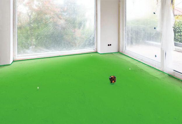
DE

E         SICHERHEITSHINWEISE
     UMSTÄNDE, DIE DAS MESSERGEBNIS VERFÄLSCHEN KÖNNEN

     Messungen durch Glas- oder Plastikscheiben; verschmutzte Laseraustrittsfenster; Sturz oder starker Stoß. Bitte
     Genauigkeit überprüfen.
     Große Temperaturveränderungen: Wenn das Gerät aus warmer Umgebung in eine kalte oder umgekehrt gebracht
     wird, vor Benutzung einige Minuten warten.

     UMGANG UND PFLEGE

     Messinstrumente generell sorgsam behandeln. Nach Benutzung mit weichem Tuch reinigen (ggfs. Tuch in etwas
     Wasser tränken). Wenn das Gerät feucht war, sorgsam trocknen. Erst in den Koffer oder die Tasche packen, wenn es
     absolut trocken ist. Transport nur in Originalbehälter oder -tasche.

     ELEKTROMAGNETISCHE VERTRÄGLICHKEIT

     Es kann nicht generell ausgeschlossen werden, dass das Gerät andere Geräte stört (z.B. Navigationseinrichtungen);
     durch andere Geräte gestört wird (z.B. elektromagnetische Strahlung bei erhöhter Feldstärke z.B. in der unmittel-
     baren Nähe von Industrieanlagen oder Rundfunksendern).

     CE-KONFORMITÄT

     Das Gerät hat das CE-Zeichen gemäß den Normen EN 61010-1:2001 + corrig. 1+2.

     GARANTIE

     Die Garantiezeit beträgt zwei (2) Jahre, beginnend mit dem Verkaufsdatum. Die Garantie erstreckt sich nur auf
     Mängel wie Material-oder Herstellungsfehler, sowie die Nichterfüllung zugesicherter Eigenschaften. Ein Garantie-
     anspruch besteht nur bei bestimmungsgemäßer Verwendung. Mechanischer Verschleiß und äußerliche Zerstörung
     durch Gewaltanwendung und Sturz unterliegen nicht der Garantie. Der Garantieanspruch erlischt, wenn das Gehäuse
     geöffnet wurde. Der Hersteller behält sich vor, im Garantiefall die schadhaften Teile instand zusetzen bzw. das Gerät
     gegen ein gleiches oder ähnliches (mit gleichen technischen Daten) auszutauschen. Ebenso gilt das Auslaufen der
     Batterie nicht als Garantiefall.

     HAFTUNGSAUSSCHLUSS

     1.    Der Benutzer dieses Produktes ist angehalten, sich exakt an die Anweisungen der Bedienungsanleitung zu hal-
           ten. Alle Geräte sind vor der Auslieferung genauestens überprüft worden. Der Anwender sollte sich trotzdem
           vor jeder Anwendung von der Genauigkeit des Gerätes überzeugen.
     2.    Der Hersteller und sein Vertreter haften nicht für fehlerhafte oder absichtlich falsche Verwendung sowie daraus
           eventuell resultierende Folgeschäden und entgangenen Gewinn.
     3.    Der Hersteller und sein Vertreter haften nicht für Folgeschäden und entgangenen Gewinn durch Naturkatastro-
           phen wie z.B. Erdbeben, Sturm, Flut, usw. sowie Feuer, Unfall, Eingriffe durch Dritte oder einer Verwendung
           außerhalb der üblichen Einsatzbereiche.
     4.    Der Hersteller und sein Vertreter haften nicht für Schäden und entgangenen Gewinn durch geänderte oder
           verlorene Daten, Unterbrechung des Geschäftsbetriebes usw., die durch das Produkt oder die nicht mögliche
           Verwendung des Produktes verursacht wurden.
     5.    Der Hersteller und sein Vertreter haften nicht für Schäden und entgangenen Gewinn resultierend aus einer
           nicht anleitungsgemäßen Bedienung.
     6.    Der Hersteller und sein Vertreter haften nicht für Schäden, die durch unsachgemäße Verwendung oder in
           Verbindung mit Produkten anderer Hersteller verursacht wurden.

10
DE
BESTIMMUNGSGEMÄSSE VERWENDUNG
Das Gerät sendet einen sichtbaren Laserstrahl aus, um z.B. folgende Messaufgaben durchzuführen: Ermittlung von
Höhen; rechten Winkeln, Ausrichtung von horizontalen und vertikalen Bezugsebenen (je nach Gerät).
WARN- UND SICHERHEITSHINWEISE
·· Richten Sie sich nach den Anweisungen der Bedienungsanleitung.
·· Anleitung vor Benutzung des Gerätes lesen.
·· Blicken Sie niemals in den Laserstrahl, auch nicht mit optischen Instrumenten. Es besteht die Gefahr von Augen-
schäden.
·· Laserstrahl nicht auf Personen richten.
·· Die Laserebene soll sich über der Augenhöhe von Personen befinden.
·· Niemals das Gehäuse öffnen. Reparaturen nur vom autorisierten Fachhändler durchführen lassen.
·· Keine Warn- oder Sicherheitshinweise entfernen.
·· Lasergerät nicht in Kinderhände gelangen lassen.
·· Gerät nicht in explosionsgefährdeter Umgebung betreiben.
·· Diese Gebrauchsanleitung ist aufzubewahren und bei Weitergabe der Lasereinrichtung mitzugeben.
LASERKLASSIFIZIERUNG
Das Gerät entspricht der Lasersicherheitsklasse 2 gemäß der Norm DIN IEC 60825-1:2014.
Das Gerät darf ohne weitere Sicherheitsmaßnahmen eingesetzt werden.
Das Auge ist bei zufälligem, kurzzeitigem Hineinsehen in den Laserstrahl durch den Lidschlussreflex geschützt.
Laserwarnschilder der Klasse 2 sind gut sichtbar am Gerät angebracht.
www.geo-fennel.de
GERMANY
Laser
2
IEC 60825-1:2014
P ≤ 1 mW @ 515 - 530 nm
Bitte unbedingt beachten:
Wenn Sie Geräte zur Reparatur / zur Justage an uns zurücksenden, entnehmen Sie bitte unbedingt aus
Sicherheitsgründen Akkus oder Batterien aus dem Gerät!
Danke.
11EN
Dear customer,
Thank you for your confidence in us having purchased a geo-FENNEL instrument.
This manual will help you to operate the instrument appropriately.
Please read the manual carefully - particularly the safety instructions. A proper use only guarantees a
longtime and reliable operation.
geo-FENNEL
Precision by tradition.
Contents
1. Supplied with A
2. Power supply B
3. Operating elements C
4. Operation D
5. Safety notes E
A SUPPLIED WITH
·· Line laser Geo6-XR GREEN SP
·· Li-Ion battery
·· Charger + USB 3.0 Cable
·· Battery case for alkaline batteries
·· Height adjustable platform
·· Wallmount
·· Support rail
·· 20 mm fix-height adapter with 5/8“
·· 3 x Height checking pins
·· Magnetic target
·· Container
·· User manual
12EN
FEATURES
·· 3 x 360° lines
=> form 6 laser crosses
·· Laser lines switchable separately
·· Plumbing function
·· Minimum laser plane distance to floor 8 mm
·· Minimum laser plane distance to wall 6 mm
·· Height adjustable platform in a range of 25 to 85 mm
·· Wallmount
·· - height and side adjustable
·· - for wall-hanging with screw / nail
·· - strong magnet on back side
·· - strap attachement
·· Visual and audible alarm when out of level
·· Self-levelling function can be locked for manual use
·· 5/8“ tripod connection (bottom side / with adapter)
·· 1/4“ tripod connection
·· Use with receiver (optional)
Technical data
Self-levelling range ± 3°
Accuracy ±2 mm / 10 m
Working range
·· without receiver 40 m* (radius)
·· with receiver (optional) 60 m** (radius)
Power supply / operating time
·· 1 x 360° 15 h / Li-Ion
·· 2 x 360° 7 h / Li-Ion
·· 3 x 360° 5 h / Li-Ion
Dust / water protection IP 54
Laser diode / laser class green / 2
Temperature range -10°C - +45°C
Dimensions 115 x 96 x 118 mm
Weight 0,8 kg
*depending on the room illumination
**depending on the direction of the laser
13EN
B POWER SUPPLY
ALKALINE BATTERIES
Open the battery compartment cover (4) and
remove the alkaline battery box. Insert alkaline
batteries (take care of correct polarity!) and
insert the box into the battery case. Close the
battery compartment cover. In case the ON/
OFF LED starts flashing the batteries must be
exchanged or the rechargeable battery must be
charged.
RECHARGEABLE BATTERY
Open the battery compartment cover (4) and
insert the rechargeable battery pack. Close the
battery compartment cover.
Take the rechargeable battery off the instru-
ment to charge it. Insert it again when the
battery is fully charged.
The ON/OFF LED shows the battery status:
if it is flashing the battery power is too weak.
The charger shows the charging status of the
instrument as below:
Permanent red light indicates that the battery is
being charged.
Permanent green light indicates that the battery
is fully charged.
The charger also serves as a permanent power
supply. The connection has to be made with
socket (5) - see top of page 15).
The rechargeable battery will note be
charged over this connection!
14EN
OPERATING ELEMENTS C
1. 1/4“ thread
2. Vial
3. Keypad 1
2
4. Battery compartment cover 4
5. Connection for permanent power supply
6. Laser emitting window
7. ON/OFF knob (transport lock)
6
3
7
5
6
Receiving mode /
MANUAL
MANUAL function
LED
Receiving LED vertical line V
ON/OFF LED horizontal line H
15EN
ACCESSSORIES
Height adjustable platform
·· individually height-adjustable platform in
the range of 25 to 85 mm; for height-
correct laying of floor tiles
non-slip
height surface
adjustment
knob
Wallmount
·· height adjustable with swivel-mounted
support rail
Support rail
·· free-hanging tripod mounting for best
line visibility at the floor
16EN
20 mm fix-height adapter with 5/8“
·· for use on the floor direct
·· for connection to a tripod with 5/8“
·· fix height: 20 mm from the bottom line
to the laser plane
Height checking pins
·· checking of floor flatness by use of
height-check pins
·· Horizontal and vertical levelling with 3 x 360° green laser lines
·· Generating right angles everywhere at the floor for straight and
diagonal layout of tiles
·· Creation and verification of correct flooring height
·· Checking planarity at wall and floor
17EN
D OPERATION
Setting up the laser:
1. click the laser onto the 20 mm fix-height adapter and align it on the floor
2. click the laser onto the 20 mm fix-height adapter and fix it onto a tripod
3. set the laser onto the heigt adjustable platform and align it on the floor
4. fix it onto a tripod by means of the support rail
5. fix the magnets of the wallmount onto a magnetic surface (steel plate)
6. set up the laser in a hanging position by means of the hole of the wallmount
7. conncet the laser to a column by means of the fixing strap
8. set up the laser on the floor direct
·· Minimum laser plane distance to floor 8 mm
·· Minimum laser plane distance to wall 6 mm
POWER ON
Power on the laser by turning the ON/OFF knob in position ON. The instrument is now ready for use.
An audible and optical (blinking lines) alarm indicates if the instrument was set up outside of the com-
pensator range. Set up the instrument on a more even surface.
To power the instrument off turn the ON/OFF knob back
to the OFF position. The instrument is now powered off.
NOTE:
During transport the ON/OFF knob (compensator lock)
must be set to OFF. Disregard may lead to damages of
the compensator.
18EN
SWITCHABLE
LASER LINES
MANUAL FUNCTION
If the instrument is in OFF position press the button MANUAL function to enter into the MANUAL
mode; the ON/OFF LED is illuminated, the MANUAL LED is blinking. Now the instrument can be
used in slope mode, the compensator alarm is off. All lines can now be switched as in standard mode.
Switch off the MANUAL function with the button MANUAL function
USE WITH RECEIVER
To prolong the working range or at unfavourable light conditions Geo6-XR GREEN SP can be used with
an optional receiver (not included in this kit).
Switch on the desired laser lines and press the button receivng mode at the laser (the LED for the
corresponding lines flashes).The selected laser lines can now be deteced by the receiver
(the visibility of the laser lines is weaker in this mode).
By use of the receiver the working range can be extended up to 60 meters. For more detailed inform-
ation please see the user manual of the receivers.
Press the button receiving mode again to quit this mode.
19EN
E SAFETY NOTES
SPECIFIC REASONS FOR ERRONEOUS MEASURING RESULTS
Measurements through glass or plastic windows; dirty laser emitting windows; after the instrument has been drop-
ped or hit. Please check the accuracy.
Large fluctuation of temperature: If the instrument will be used in cold areas after it has been stored in warm areas
(or the other way round) please wait some minutes before carrying out measurements.
CARE AND CLEANING
Handle measuring instruments with care. Clean with soft cloth only after any use. If necessary damp the cloth with
some water. If the instrument is wet clean and dry it carefully. Pack it up only if it is perfectly dry. Transport in original
container / case only.
ELECTROMAGNETIC ACCEPTABILITY (EMC)
It cannot be completely excluded that this instrument will disturb other instruments (e.g. navigation systems); will be
disturbed by other instruments (e.g. intensive electromagnetic radiation nearby industrial facilities or radio transmit-
ters).
CE-Conformity
The instrument has the CE mark according to EN 61010-1:2001 + corrig. 1+2.
WARRANTY
This product is warranted by the manufacturer to the original purchaser to be free from defects in material and work-
manship under normal use for a period of two (2) years from the date of purchase. During the warranty period, and
upon proof of purchase, the product will be repaired or replaced (with the same or similar model at manufacturers
option), without charge for either parts or labour. In case of a defect please contact the dealer where you originally
purchased this product. The warranty will not apply to this product if it has been misused, abused or altered. Without
limiting the foregoing, leakage of the battery, bending or dropping the unit are presumed to be defects resulting from
misuse or abuse.
EXCEPTIONS FROM RESPONSIBILITY
1. The user of this product is expected to follow the instructions given in the user manual. Although all
instruments left our warehouse in perfect condition and adjustment the user is expected to carry out periodic
checks of the product’s accuracy and general performance.
2. The manufacturer, or its representatives, assumes no responsibility of results of a faulty or intentional usage or
misuse including any direct, indirect, consequential damage, and loss of profits.
3. The manufacturer, or its representatives, assumes no responsibility for consequential damage, and loss of
profits by any disaster (earthquake, storm, flood etc.), fire, accident, or an act of a third party and/or a usage in
other than usual conditions.
4. The manufacturer, or its representatives, assumes no responsibility for any damage, and loss of profits due to
a change of data, loss of data and interruption of business etc., caused by using the product or an unusable
product.
5. The manufacturer, or its representatives, assumes no responsibility for any damage, and loss of profits caused
by usage other than explained in the user manual.
6. The manufacturer, or its representatives, assumes no responsibility for damage caused by wrong movement or
action due to connecting with other products.
20EN
INTENDED USE OF INSTRUMENT
The instrument emits a visible laser beam in order to carry out the following measuring tasks (depending on the
instrument): Setting up heights, horizontal and vertical planes, right angles.
SAFETY INSTRUCTIONS
·· Follow up the instructions given in the user manual.
·· Do not stare into the beam. The laser beam can lead to eye injury. A direct look into the beam (even from greater
distance) can cause damage to your eyes.
·· Do not aim the laser beam at persons or animals.
·· The laser plane should be set up above the eye level of persons.
·· Use the instrument for measuring jobs only.
·· Do not open the instrument housing. Repairs should be carried out by authorized workshops only. Please contact
your local dealer.
·· Do not remove warning labels or safety instructions.
·· Keep the instrument away from children.
·· Do not use the instrument in explosive environment.
·· The user manual must always be kept with the instrument.
LASER CLASSIFICATION
The instrument is a laser class 2 laser product according to DIN IEC 60825-1:2014.
It is allowed to use the unit without further safety precautions.
The eye protection is normally secured by aversion responses and the blink reflex.
The laser instrument is marked with class 2 warning labels.
www.geo-fennel.de
GERMANY
Laser
2
IEC 60825-1:2014
P ≤ 1 mW @ 515 - 530 nm
Please note:
If you return instruments for repair / for adjustment to us please disconnect batteries or rechargeable
batteries from the instrument - this is for safety reasons!
Thank you.
21FR
Cher client,
Nous tenons à vous remercier pour la confiance que vous avez témoignée, par l‘acquisition de votre
nouvel instrument geo-FENNEL.
Les instructions de service vous aideront à vous servir de votre instrument de manière adéquate.
Nous vous recommandons de lire avec soin tout particulièrement les consignes de sécurité de ladite
notice avant la mise en service de votre appareil. Un emploi approprié est l‘unique moyen de garantir
un fonctionnement efficace et de longue durée.
geo-FENNEL
Precision by tradition.
Contenu
1. Contenu A
2. Alimentation en courant B
3. Description C
4. Opération D
5. Consignes de sécurité E
A CONTENU
·· Laser lignes Geo6-XR GREEN SP
·· Batterie Li-Ion
·· Chargeur + cable USB 3.0
·· Boîtier pour piles alcalines
·· Plateforme ajustable en hauteur
·· Support mural
·· Support rail
·· Adaptateur 20 mm avec 5/8 "
·· 3 plots de contrôle de hauteur
·· Cible magnétique
·· Coffret rigide
·· Mode d‘emploi
22FR
CARACTÉRISTIQUES
·· 3 lignes 360°
=> génèrent 6 croix laser
·· Lignes laser s'allument indépendement
·· Fonction d'aplomb
·· Distance minimum du sol 8 mm
·· Distance minimum du mur 6 mm
·· Plateforme ajustable en hauteur de 25 à 85mm
·· Support mural
·· -réglable hauteur et latéral
·· -support mural fixation par vis
·· -aimant puissant sur le dos du support
·· -fixation par sangle
·· Alarme visuelle et sonore quand il n'est pas de niveau
·· Possibilité de bloquer le laser pour travail en manuel
·· Filetage 5/8'' (en dessous avec adaptateur)
·· Filetage 1/4" (au dessus)
·· Fonctionne avec cellule (en option)
Données techniques Geo6X SP
Plage d‘auto-nivellement ± 3°
Précision ±2 mm / 10 m
Portée
·· sans cellule 40 m* ( rayon)
·· avec cellule (en option) 60 m** (rayon)
Alimentation / autonomie
·· 1 x 360° 15 h / Alkaline
·· 2 x 360° 7 h / Alkaline
·· 3 x 360° 5 h / Alkaline
Étanchéité IP 54
Diode de laser / classe de laser vert / 2
Plage de température -10°C à +45°C
Dimensions 115 x 96 x 118 mm
Poids (instrument avec batterie) 0,8 kg
*en fonction des conditions lumineues
**depend de la direction du laser
23FR
B ALIMENTATION EN COURANT
PILES ALCALINES
Ouvrez le clapet du compartiment piles (4) et
retirez le bloc de piles de secours. Y placez
les piles alcalines (prenez soin de la polarité) et
remettez le bloc dans l‘instrument. Fermez le
clapet.
Si la diode MARCHE/ARRÊT clignote les piles
doivent être changées our l‘accu doit être
chargé.
BATTERIE LI-ION
Ouvrez le clapet du compartiment piles (4) et y
placez la batterie Li-Ion. Fermez le clapet.
Enlevez la batterie Li-Ion de l‘instrument pour
la charger. Après le chargement insérez-la de
nouveau dans l‘instrument.
La diode MARCHE/ARRÊT affiche également
l‘état de la batterie. Si elle commence à clig-
noter la batterie est faible.
ÉTAT DE LA BATTERIE
La lumière rouge permanente (sur le chargeur)
indique que les batteries sont en train d‘être
chargées.
La lumière verte permanente (sur le chargeur)
indique que les batteries sont complètement
chargées.
Le chargeur peut être utilisé pour alimentation
en courant permanente. La connexion se fait
par la douille extérieure (5) - voir en haut de la
page 25.
L‘ accu ne va pas être chargé sur cette
connexion!
24FR
DESCRIPTION C
1. Filetage 1/4“
2. Nivelle
3. Clavier 1
2
4. Couvercle du logement de piles 4
5. Douille pour alimentation en permanence
6. Fenêtre de sortie des faisceaux laser
7. Interrupteur MARCHE/ARRÊT
(blocage compensateur)
6
3
7
5
6
Diode fonction Touche fonction réception
MANUEL Touche fonction MANUEL
Diode fonction Touche ligne verticale V
réception
Diode MARCHE/
Touche ligne horizontale H
ARRÊT
25FR
ACCESSOIRES
Plateforme ajustable en hauteur
·· plateforme individuellement ajustable en
hauteur de 25 à 85 mm; pour une pose
correcte des carreaux au sol
superficie
bouton de réglage antiglisse
en hauteur
Support mural
·· réglable en hauteur avec support rail
pivotant
Support rail
·· support pour montage sur trépied en
suspension libre pour une meilleure
visibilité de la ligne au sol
26FR
Adaptateur 20 mm
(également pour connexion trépied 5/8„)
·· pour la mise en place directement sur
le sol
·· pour la connexion 5/8“ d‘un trépied
·· hauteur fixe: 20 mm du sol à la plaine
du laser
3 plots de contrôle de hauteur
·· Contrôle de la planéité du sol avec les
3 plots de contrôle de hauteur
·· 3 lignes laser horizontales et verticales vertes à 360°
·· Génère des equerrages partout au sol pour l'aide
aux alignements droits et diagnonals des carreaux
·· Création et contrôle des hauteurs des revêtements de sol
·· Contrôle de la planéité des sols et murs
27FR
D OPÉRATION
Mise en place de l‘appareil:
1. cliquez le laser sur l‘adaptateur 20 mm et le placez sur le sol
2. cliquez le laser sur l‘adaptateur 20 mm et le placez sur un trépied
3. fixez le laser sur la plateforme ajustable en hauteur et le placez sur le sol
4. fixez le laser sur un trépied à l‘aide du support rail
5. fixer l’ensemble sur une surface magnétique par les aimants de l’attache
6. suspendre l’ensemble sur une vis passant dans le trou de l’attache
7. fixer l’ensemble sur une colonne à l’aide des courroies de l’attache
8. positionnez le laser sur le sol directement
·· Distance minimum du sol 8 mm
·· Distance minimum du mur 6 mm
MARCHE / ARRÊT
Mettez le bouton marche/arrêt (ON/OFF) en position ON. Le laser est prêt à fonctionner. Le laser
émettra un bip sonore qui vous signalera qu‘il est dehors de sa plage de compensation automatique.
Les lignes de laser en circuit clignotent pour servir d‘avertissement complémentaire.
Arrêt du laser: Mettez le bouton marche/arrêt (ON/OFF) en
position OFF. A présent l‘appareil est mis hors service.
Attention:
Avant de remiser l‘appareil dans le coffret, le socle doit
toujours se trouver sur la position OFF. Un signal d‘aver-
tissement sonore retentit si cela n‘a pas été fait.
28FR
LIGNES POUVANT
ÊTRE PROJETÉES
FONCTION MANUEL
Lorsque l’instrument se trouve en position OFF, pressez la touche fonction MANUEL une seule fois
pour mettre en circuit la fonction MANUEL. La diode ON/OFF s’allume, la diode MANUEL clignote et
les lignes laser sont en mesure de fonctionner. L’instrument peut alors être utilisé en position inclinée
et l’alarme du compensateur est hors circuit. A présent toutes les lignes peuvent être mis en circuit
en opérant comme décrit en dessous. Opérez de même, pour remettre hors circuit la fonction MANU-
EL
à l’aide de la touche fonction MANUEL.
UTILISATION AVEC CELLULE (EN OPTION)
Pour l‘allongement de la plage de travail ou pour l‘emploi dans des conditions de luminosité intense, il
est possible d‘utiliser le Geo6-XR GREEN SP avec une cellule (ne pas inclus dans la livraison).
Mettez en circuit les lignes laser désirées et pressez la touche fonction réception de l‘ appareil (le
voyant de contrôle des lignes laser concernées clignote). Ainsi les lignes laser choisies sont com-
mutées sur la marche en mode détection (les lignes laser apparaissent alors de couleur moins claire).
La plage de travail peut ainsi s‘allonger à 60 m. Pour d’autres informations, se reporter aux instruc-
tions de service de la cellule. Pressez à nouveau la touche fonction réception pour abandonner cette
fonction.
29FR
E CONSIGNES DE SÉCURITÉ
CIRCONSTANCES POUVANT FAUSSER LES RÉSULTATS DE MESURES
Mesures effectuées à travers des plaques de verre ou de matière plastique; mesures effectuées à travers la fenêtre
de sortie du faisceau laser lorsqu‘elle est sale. Mesures après que le niveau soit tombé ou ait subi un choc très fort.
Mesures effectuées pendant de grandes différences de température - p. ex. lorsque l‘instrument passe rapidement
d‘un milieu très chaud à un autre très froid; attendre alors quelques minutes d‘adaptation avant de réutiliser le
niveau.
NETTOYAGE ET REMISAGE
Essuyer l‘instrument mouillé, humide ou sali en le frottant uniquement avec un tissu de nettoyage. Quant à l‘optique,
la nettoyer avec un tissu fin comme p. ex. un tissu feutré de lunettes.
Ne jamais mettre un instrument humide dans un coffret fermé! Le laisser sécher auparavant au moins pendant un
jour dans un local chauffé! Transport seulement dans le coffret original.
COMPATIBILITÉ ÉLECTROMAGNÉTIQUE
De manière générale, il n‘est pas exclu que le niveau ne dérange d‘autres instruments (p. ex. les dispositifs de
navigation) ou qu‘il puisse lui-même être dérangé par d‘autres appareils (p. ex. soit par un rayonnement électromag-
nétique dû à une élévation de l‘intensité du champ, soit par la proximité d‘installations industrielles ou d‘émetteurs de
radiodiffusion).
CONFORMITÉ CE
Le niveau porte le label CE conformément aux normes NE 61010-1:2001.
GARANTIE
La durée de garantie est de deux (2) ans à partir de la date d‘achat. Cette garantie ne couvre que les défauts tels
que le matériel défectueux ou les anomalies de fabrication, ainsi que le manque des propriétés prévues. Le droit à
la garantie n‘est valable que si l‘utilisation du niveau a été conforme aux préscriptions. En sont exclus l‘usure méca-
nique et un endommagement externe par suite d‘usage de la force et/ou d‘une chute. Le droit à la garantie prend
fin lorsque le boîtier a été ouvert. Dans un cas couvert par la garantie, le fabricant se réserve le droit de remettre en
état les éléments défectueux ou d‘échanger l‘instrument par un autre identique ou similaire (possédant les mêmes
caractéristiques techniques). De même, un endommagement résultant d‘un écoulement de l‘accumulateur n‘est pas
couvert par la garantie.
UTILISATION CONFORME AUX PRÉSCRIPTIONS
Le niveau projette un faisceau laser visible, pour effectuer p. ex. les travaux de mesures suivants: détermination de
l‘hauteur, tracé d’angles droits, pointage de plans de référence horizontaux ainsi qu’obtention de points d’aplomb
(dépendant de l‘instrument).
Merci de respecter le suivant impérativement:
Si vous retournez des instruments pour réparation / ajustage vous devez - pour des raisons de sécurité -
impérativement enlever les accus.
Merci.
30FR
EXCLUSION DE LA RESPONSABILITÉ
1. L‘utilisateur de ce produit est tenu de respecter ponctuellement les instructions du mode d‘emploi.
Tous les instruments ont été très soigneusement vérifiés avant leur livraison. Toutefois, l‘utilisateur
devra s‘assurer de la précision de ce niveau avant chaque emploi.
2. Le fabricant et son représentant déclinent toute responsabilité dans le cas d‘utilisation incorrecte
ou volontairement anormale ainsi que pour les dommages consécutifs en découlant, tout comme
pour les bénéfices non réalisés.
3. Le fabricant et son représentant déclinent toute responsabilité pour les dommages consécutifs
et les bénéfices non réalisés par suite de catastrophes naturelles, comme p. ex. tremblement
de terre, tempête, raz de marée etc. ainsi que d‘incendie, accident, intervention malintentionnée
d‘une tierce personne, ou encore dus à une utilisation hors du domaine d‘application normal de
l‘instrument.
4. Le fabricant et son représentant déclinent toute responsabilité pour les dommages et les bé-
néfices non réalisés par suite de modification ou perte de données, interruption du travail de
l‘entreprise etc., à savoir les dommages qui découlent du produit lui-même ou de la non-utilisation
du produit.
5. Le fabricant et son représentant déclinent toute responsabilité pour les dommages et le bénéfices
non réalisés par suite d‘une manoeuvre non conforme aux instructions.
6. Le fabricant et son représentant déclinent toute responsabilité pour les dommages et les bé-
néfices non réalisés qui decoulent d‘une utilisation inadéquante ou en liaison avec des produits
d‘autres fabricants.
CLASSIFICATION DES LASERS
Ce niveau correspond à la classe de sécurité des lasers 2, conformément à la norme DIN EN 60825-1:2014. De ce
fait, l’instrument peut être utilisé sans avoir recours à d’autres mesures de sécurité. Au cas où l’utilisateur a regardé
un court instant le faisceau laser, les yeux sont tout de même protégés par le réflexe de fermeture des paupières.
Les pictogrammes de danger de la classe 2 sont bien visibles sur le niveau.
www.geo-fennel.de
GERMANY
Laser
2
IEC 60825-1:2014
P ≤ 1 mW @ 515 - 530 nm
31geo-FENNEL
geo-FENNEL GmbH
GmbH Technische
TechnischeÄnderungen
Änderungen vorbehalten.
vorbehalten.
Kupferstraße 6 All
Kupferstraße 6 All instruments
instruments subject
subject to
to technical
technical changes.
changes.
D-34225 Baunatal Sous
Sous réserve
réserve de
de modifications
modifications techniques.
techniques.
D-34225
Tel. Baunatal
+49 561 / 49 21 45
Tel.
Fax +49
+49 561
561 // 49
49 21
72 45
34
Fax
info@geo-fennel.de 72 34
+49 561 / 49
12/2014
11/2019
info@geo-fennel.de
www.geo-fennel.de
www.geo-fennel.de Precision by tradition.Sie können auch lesen